
Integration of Heterogeneous Components for Co-Simulation
Jawher Jerray
a
, Rabea Ameur-Boulifa
b
and Ludovic Apvrille
c
LTCI, T
´
el
´
ecom Paris, Institut Polytechnique de Paris, Sophia-Antipolis, France
Keywords:
Heterogeneous Models, Simulation, Formal Verification, Integration, System Design.
Abstract:
Because of their complexity, embedded systems are designed with sub-systems or components taken in charge
by different development teams or entities and with different modeling frameworks and simulation tools,
depending on the characteristics of each component. Unfortunately, this diversity of tools and semantics makes
the integration of these heterogeneous components difficult. Thus, to evaluate their integration before their
hardware or software is available, one solution would be to merge them into a common modeling framework.
Yet, such a holistic environment supporting many computation and computation semantics seems hard to settle.
Another solution we investigate in this paper is to generically link their respective simulation environments
in order to keep the strength and semantics of each component environment. The paper presents a method to
simulate heterogeneous components of embedded systems in real-time. These components can be described at
any abstraction level. Our main contribution is a generic glue that can analyze in real-time the state of different
simulation environments and accordingly enforce the correct communication semantics between components.
1 INTRODUCTION
Complex embedded systems are commonly designed
using several modeling approaches and tools, because
of the different nature of sub-systems, and because
of the use of tiers to provide equipments. Integrat-
ing such heterogeneous is known as complex because
of the diversity of models. Yet, ideally, this integra-
tion stage should be done as early as possible in the
development process of these systems to verify, e.g.,
that the interfaces and main data exchanged are as
expected, and can provide the expected overall func-
tions.
Since forcing all partners of a product to use the
same modeling languages or simulation techniques
is a too hard constraint, integration of components
designed within disparate formalisms necessitates a
methodology for interconnecting these varying for-
malisms. A first way to do would be to glue the differ-
ent meta-models of the components in order to build a
unique (meta-)model from which integration verifica-
tions can be performed. This has already been shown
in the scope of components for which their models
of computation are quite similar (Zhao et al., 2020).
Yet, when they are too different, a second approach
a
https://orcid.org/0000-0001-6170-7489
b
https://orcid.org/0000-0002-2471-8012
c
https://orcid.org/0000-0002-1167-4639
can be used: connecting these components at simula-
tion level. This paper aims to address this challenge,
concentrating specifically on data exchanges between
components. The objective is to guarantee the en-
forcement of the correct communication semantics.
In this paper, we define a method and techniques
to allow to integrate a set of models designed with dif-
ferent frameworks and simulated using their own sim-
ulator, with no modification on their simulation en-
gine. To maintain a real-time co-simulation of these
different simulators where they interoperate in realis-
tic scenarios, we propose a generic ”simulation glue”
based on a distributed event streaming platform to
join heterogeneous simulators together. . After hav-
ing defined this glue, the paper illustrates in a more
concrete way how SystemC and TTool components
can be co-simulated, using Apache Kafka as the dis-
tributed event streaming platform.
2 RELATED WORK
In the area of heterogeneous distributed systems anal-
ysis, e.g., (Basu et al., 2006; Liboni and Deantoni,
2020), most of the works are based on co-simulation,
but not many of them can support both simulation and
formal validation in the same framework.For coupling
two or more simulation tools in a co-simulation envi-
Jerray, J., Ameur-Boulifa, R. and Apvrille, L.
Integration of Heterogeneous Components for Co-Simulation.
DOI: 10.5220/0012134800003538
In Proceedings of the 18th International Conference on Software Technologies (ICSOFT 2023), pages 637-644
ISBN: 978-989-758-665-1; ISSN: 2184-2833
Copyright
c
2023 by SCITEPRESS – Science and Technology Publications, Lda. Under CC license (CC BY-NC-ND 4.0)
637

ronment, most of the approaches (e.g., (Neema et al.,
2014; Tavella et al., 2016; Mugombozi et al., 2019))
rely on the Functional Mockup Interface (FMI) Stan-
dard (Blochwitz et al., 2011) to bundle, in a single
black-box, the internal computations and the interface
descriptions of the simulation units. One of the most
difficult challenges these approaches face is dealing
with the gap between the different semantics (Tri-
pakis, 2015) of simulation units such as the various
semantics of the coordination, which can refer to con-
tinuous time or discrete events. In (Liboni and Dean-
toni, 2020), the authors have defined a language for
describing model coordination interfaces. The inter-
face is dedicated to share the elements necessary to
coordinate the execution and communication among
the simulation units. There also exist dedicated plat-
forms for the modelling and the simulation of hetero-
geneous component-based systems, examples include
(Balarin et al., 2003; Eker et al., 2003; Basu et al.,
2006). These platforms support several modeling lan-
guages with a variety of component semantics. How-
ever, they offer a general and unified framework for
the design and simulation, even for hybrid systems.
Among existing co-simulation solutions for integrat-
ing complex systems, the model transformation from
a high-level language to SystemC is proposed in the
scope of UML or SysML (Raslan and Sameh, 2007;
?; ?). In (Atitallah et al., 2008), the authors propose a
tool to transform a high level MARTE description into
an executable platform via a chain of model transfor-
mations. These solutions are relatively tedious since
the transformation of high-level languages into tradi-
tional simulation or verification must preserve the se-
mantics, which is commonly tedious for supporting
correctly communication and computation semantics.
Moreover, all modeling environments must propose
a model transformation to the same target language
(e.g., SystemC) and the simulation specifications ob-
tained from high-level languages must still be inte-
grated together.
3 SIMULATING
HETEROGENEOUS MODELS
This section presents our contribution: a new frame-
work for the integration of heterogeneous components
using a simulation integration platform. This integra-
tion platform is agnostic to the simulation technology,
as long as it supports the communication semantics
described in this section.
Model
M
1
I
1
I
′
1
I
′
2
O
1
O
′
1
O
′
2
Model
M
2
I
1
I
′
1
I
′
2
O
1
O
′
1
Model
M
3
I
1
I
′
1
O
1
O
′
1
O
′
2
Glued models
Distributed event
streaming platform
Figure 1: Communication between models and the dis-
tributed event streaming platform.
3.1 Component Model
A model defines components interconnected with
ports. A model supports 4 types of ports: internal
input ports I
i
, external input ports I
′
j
, internal output
ports O
k
and external output ports O
′
l
. A model M
has m internal input ports, n external input ports, p
internal output ports and q external output ports as
shown in Fig. 1. We assume that the objective is to
co-simulate a set of components C . We assume that
the simulation engine of each c ∈ C can already han-
dle communications internal to c. Thus, in this paper,
we focus on external input ports I
′
j
and external output
ports O
′
l
.
In this paper, we consider two modeling
frameworks and their corresponding meta-models:
TTool (TTo, 2023) and SystemC. The former can be
used to capture SysML components that can be sim-
ulated with the internal simulator (Knorreck et al.,
2009) of TTool to prove safety and performance prop-
erties. The latter uses components written in C++ and
simulated with the SystemC simulation engine.
3.2 Distributed Event Streaming
Platform
We assume that a facility, part of our contribution,
can stream events to distributed senders/receivers so
as to ensure data can be sent and received, in real-
time, by the simulation engines of components.
Apache Kafka. Apache Spark, Apache Kafka,
Apache Flink and Spring Cloud Data Flow are ex-
ample of streaming platforms. We decided to rely
on Apache Kafka to forward messages between sim-
ulation engines. Indeed, Kafka supports many com-
puting platforms and can also handle distributed and
event-based communications. Yet, Kafka cannot na-
tively support the communication semantics usually
found in modeling frameworks for embedded sys-
tems, for instance the exchange of values via FIFOs.
Yet, Kafka supports the notion of broker: a broker
ICSOFT 2023 - 18th International Conference on Software Technologies
638

contains a set of topics, and each topic has a set of
partitions that can be considered as an infinite FIFO
buffer.To send messages to a partition, we rely on pro-
ducers. A producer can send messages to different
partitions in different topics. Consumers can receive
messages from partitions. Partitions are configured at
co-simulation setup.
3.3 Communication
In Fig. 1, we give an example of the simulation in-
tegration between 3 models via a distributed event
streaming platform, where:
• Model M
1
has 2 external input ports I
′
1
and I
′
2
and
2 external output ports O
′
1
and O
′
2
.
• Model M
2
has 2 external input ports I
′
1
and I
′
2
and
1 external output port O
′
1
.
• Model M
3
has 1 external input port I
′
1
and 2 exter-
nal output ports O
′
1
and O
′
2
.
The distributed event streaming platform must ensure
communications, for example from external output
O
′
1
of M
1
to external input I
′
1
of M
2
.
Fig. 2 depicts the general approach of our con-
tribution. First, we assume that a user wants to co-
simulate at least two models having possibly different
meta-models. From those models, our contribution
automatically updates these models to allow them to
interact with our co-simulation framework. Then, us-
ing these Co-simulation models, we start the corre-
sponding simulation of each model at the same time.
We assume we can access to the simulation trace of
each simulation when they are running: what is of in-
terest for us is obviously to identify all the potential
read or write transactions on external ports. Indeed,
the co-simulator retrieves information that being sent
or received on each port. When data is ready to be
sent on an external output port, our co-simulator en-
sures data are forwarded to the corresponding external
input port while enforcing the communication seman-
tics, e.g., finite or infinite FIFO, exchange of values or
exchange of a quantity of information.
Fig. 3 zooms on the co-simulation box shown
in Fig. 2. The co-simulator is in charge of stream rout-
ing. For each model, the co-simulator manages the
sending and receiving of data from the event stream-
ing platform depending on the port type and the cur-
rent status of ports.
3.4 Co-Simulation Models
The purpose of modifying the original models is to
facilitate communication between the simulation of a
model and the co-simulation. Co-simulation models
are automatically generated from the original model.
The Co-simulation models are automatically gener-
ated from a given model.
Algorithm 1: Algorithm of the creation of the Co-simulation
TTool model.
1 for each
i input channel in list input channels do
2 disconnect port from origin side
(i input channel); /* Disconnect the external
port from its origin. */
3 create new task(); /* Create new task for the
external input channel. */
4 connect port to new task(i input channel);
/* Connect the external port to the new task. */
5 add event(i input channel); /* Add an event
to the new task, this event will retrieve data from
the co-simulator using the avs command that allows
to add signals to a given event. */
6 associate activity diagram to task
(i input channel); /* Create the activity
diagram of the new task that contains an infinite
loop with a read event to get the data sent by the
co-simulator followed by a write channel to insert
the data to the model. */
7 add CPU in architecture(i input channel);
/* Add a new CPU in the architecture and associate
the created task to it. */
8 link CPU to bus(i input channel); /* Link
the new CPU to the main Bus. */
9 end
10 for each
i out put channel in list out put channels do
11 disconnect port from destination side
(i output channel); /* Disconnect the
external port from its destination. */
12 create new task(); con-
nect port to new task(i output channel);
add event(i output channel);
13 associate activity diagram to task
(i output channel); /* Create the activity
diagram of the new task that contains an infinite
loop with a read event, followed by a read channel
to remove samples from the channel. */
14 add CPU in architecture(i output channel);
link CPU to bus(i output channel);
15 end
Algorithm to Create a Co-Simulation TTool
Model, as Shown in Fig. 2. A TTool model con-
sists of two views: a functional view and a hard-
ware view. In the functional view, SysML blocks are
used to describe the functions and their communica-
Integration of Heterogeneous Components for Co-Simulation
639

<<component>>
Co-simulation
<<component>>
Simulation of Model 1
<<component>>
Model 1
<<component>>
Trace of Model 1
<<component>>
Co-simulation Model 1
Text
Automatic adjustment
<<component>>
Model 2
<<component>>
Co-simulation Model 2
Automatic adjustment
<<component>>
Model n
<<component>>
Co-simulation Model n
Automatic adjustment
run
<<component>>
Simulation of Model 2
run
<<component>>
Simulation of Model n
run
<<component>>
Trace of Model 2
generate generate
<<component>>
Trace of Model n
generate
parse
parse
parse
retrieve informationretrieveinformation
retrieveinformation
Figure 2: An overview of the proposed approach.
Figure 3: Zoom in the ”Co-simulation” box.
tion. The behaviour of each function is given with
an Activity Diagram. Functions can communicate to-
gether using two different facilities: event and data
channels. Events can be used to exchange control val-
ues. Data channels are used to capture the exchange
of a quantity of information. In the hardware view,
functional blocks are allocated to blocks representing
hardware components: processors, buses and memo-
ries. Functions are to be allocated to execution com-
ponents (e.g., processors), and data communication
are mapped to buses and memories. Events are not
mapped since the traffic induced by control signals
is usually considered as negligible. Events and data
channels support different semantics, such as finite
FIFO, infinite FIFO, etc.
Handling a communication (events, data) with a
model external to TTool means that the hardware plat-
form modeled in TTool must contain a input/output
hardware device from which all system components
can be reached. This is how this is achieved in em-
bedded systems: a communication interface must be
used for input and output operations with the environ-
ment.
As a consequence, sending information to a com-
ponent external to the TTool’s model means that
transactions on memories and on buses leading to the
communication interface device must be taken into
account when simulating the TTool model. Thus,
when connecting TTool’s simulator with another sim-
ulator, we decided to add one hardware I/O device per
output or input channel, and the necessary connection
to buses and memories of the hardware part of the
TTool model. Moreover, we map to each hardware
device one function f
c
e
. The activity diagram of f
c
e
features a main loop, which is infinite. In the case of
an input device, the loop contains a wait event oper-
ICSOFT 2023 - 18th International Conference on Software Technologies
640
Input
comm_2
evt_1
comm_1
Output
evt_2
comm_3
comm_3
comm_1
evt_1
comm_2
evt_2
Component
evt_1
comm_2
comm_3
evt_2
comm_1
Input
comm_2
evt_1
comm_1
Output
evt_2
comm_3
comm_3
comm_1
evt_1
comm_2
evt_2
Component
evt_1
comm_2
comm_3
evt_2
comm_1
—————————————————————————————————————
evt_2
Input
evt_1
TASK_INP_COMMUNIC_CHANNEL_comm_2
- nbr_samples_input_from_kafka_comm_2 = 0 : Natural;
comm_2
goTM_IN_comm_2 goTM_IN_comm_2
TASK_INP_COMMUNIC_CHANNEL_comm_1
- nbr_samples_input_from_kafka_comm_1 = 0 : Natural;
comm_1
goTM_IN_comm_1 goTM_IN_comm_1
goTM_OUT_comm_3
goTM_IN_comm_2
goTM_IN_comm_1
evt_1
comm_3
Output
evt_2
TASK_OUTP_COMMUNIC_CHANNEL_comm_3
- nbr_samples_output_from_kafka_comm_3 = 0 : Natural;
comm_3
goTM_OUT_comm_3 goTM_OUT_comm_3
comm_1
comm_2
Component
comm_1
comm_2 comm_3
evt_1
evt_2
evt_2
Input
evt_1
TASK_INP_COMMUNIC_CHANNEL_comm_2
- nbr_samples_input_from_kafka_comm_2 = 0 : Natural;
comm_2
goTM_IN_comm_2 goTM_IN_comm_2
TASK_INP_COMMUNIC_CHANNEL_comm_1
- nbr_samples_input_from_kafka_comm_1 = 0 : Natural;
comm_1
goTM_IN_comm_1 goTM_IN_comm_1
goTM_OUT_comm_3
goTM_IN_comm_2
goTM_IN_comm_1
evt_1
comm_3
Output
evt_2
TASK_OUTP_COMMUNIC_CHANNEL_comm_3
- nbr_samples_output_from_kafka_comm_3 = 0 : Natural;
comm_3
goTM_OUT_comm_3 goTM_OUT_comm_3
comm_1
comm_2
Component
comm_1
comm_2 comm_3
evt_1
evt_2
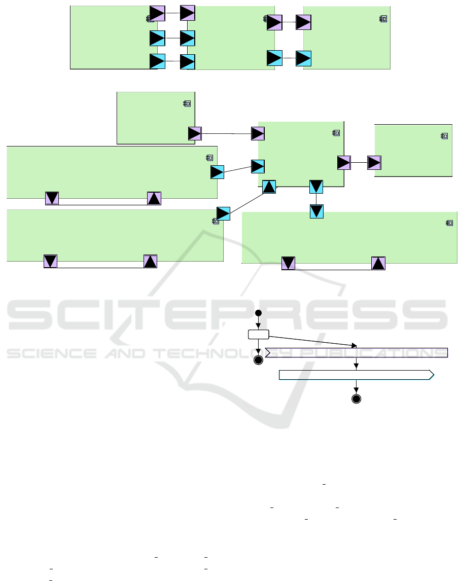
Figure 4: Top: The original Task diagram of the initial model. Bottom: The auto-generated task diagram of the Co-simulation
model.
ator that makes it possible to receive the number of
samples to be read (i.e., the quantity of information).
The wait event is followed by a read channel opera-
tor. In the case of an output device, the infinite loop
had a send event to send to the destination the num-
ber of samples to be read, and then a write operator.
Algorithm 1 formalizes the different steps necessary
to prepare a TTool model for external co-simulation:
this includes creating the new functions f
c
e
and their
behavior, creating the hardware I/O devices p
c
e
, con-
necting them to the corresponding bus, and connect-
ing the new ports (ports of f
c
e
) to the corresponding
sending ou receiving functions.
4 IMPLEMENTATION OF OUR
APPROACH
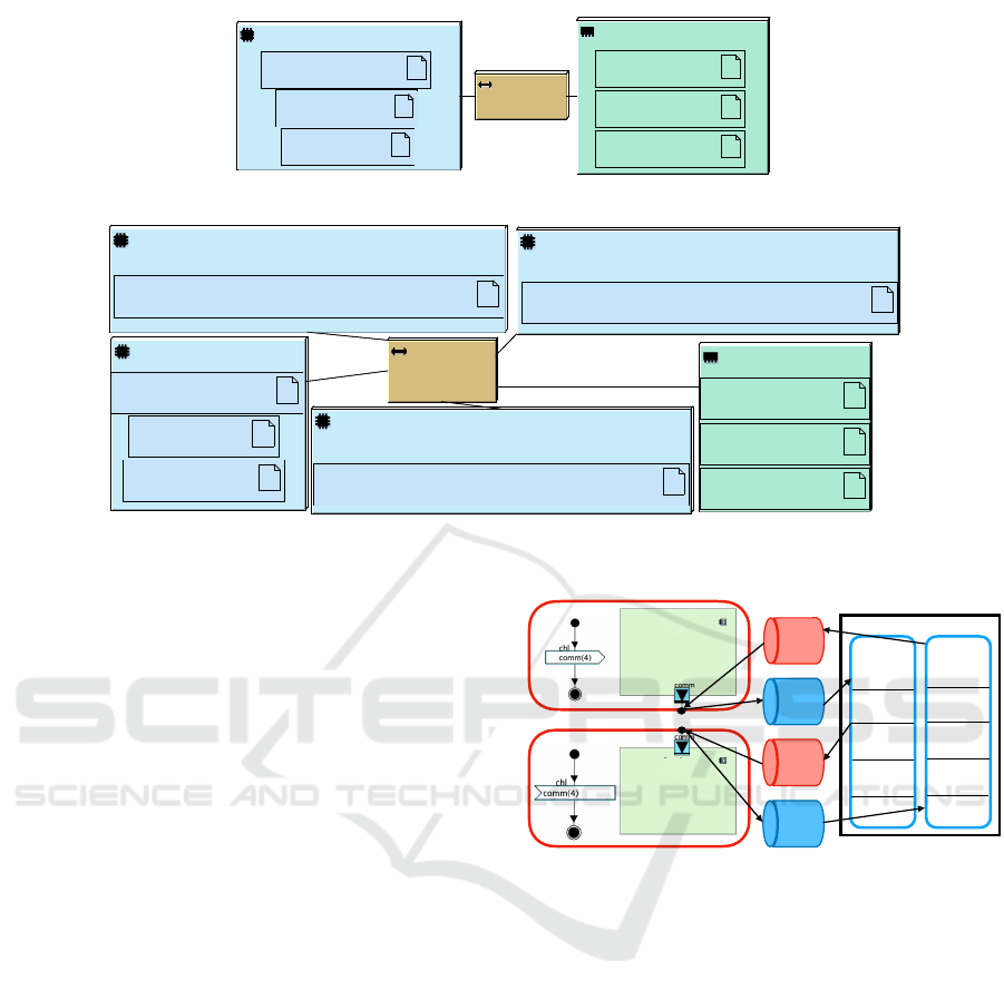
An Example of Generating Automatically a Co-
Simulation TTool Model. Let’s consider an exam-
ple with 3 external input ports (”evt 1”, ”comm 1”
and ”comm 2”) and 2 external output ports (”evt 2”
and ”comm 3”). The top part of the functional view
in Fig. 4 and the top part of the architecture in Fig. 6
depict functional components and the allocation of
components to the related architecture, respectively.
The application of Algorithm 1 to this model au-
chl
comm_1(nbr_samples_input_from_kafka_comm_1)
evt
goTM_IN_comm_1(nbr_samples_input_from_kafka_comm_1)
for(;;)
inside loop
exit loop
chl
comm_1(nbr_samples_input_from_kafka_comm_1)
evt
goTM_IN_comm_1(nbr_samples_input_from_kafka_comm_1)
for(;;)
inside loop
exit loop
Figure 5: The auto-generated activity diagram for Channel
comm
1
.
tomatically transforms the component view to the
one given at the bottom of Figure Fig. 4. Similarly,
the activity diagram of the new task of the exter-
nal channel ”comm 1” is shown in Fig. 5, the ac-
tivity diagrams of the tasks of the external channels
”comm 2” and ”comm 3” are similar to that of the
channel ”comm 1”, but its of ”comm 3” has a chan-
nel read operator instead of the channel write opera-
tor. Also, bottom part of Figure Fig. 6 depicts the new
hardware architecture.
Automatic Handling of Communication Semantics
via Kafka. The general idea behind our contribu-
tion is to automatically create the necessary Kafka
partitions to handle the communication semantics,
e.g., to manage the number of events or data samples
Integration of Heterogeneous Components for Co-Simulation
641
<<CPURR>>
CPU0
Application::Component
Application::Output
Application::Input
<<BUS-RR>>
Bus0
<<MEMORY>>
Memory0
Application::comm_2
channel
Application::comm_1
channel
Application::comm_3
channel
<<CPURR>>
CPU0
Application::Component
Application::Output
Application::Input
<<BUS-RR>>
Bus0
<<MEMORY>>
Memory0
Application::comm_2
channel
Application::comm_1
channel
Application::comm_3
channel
—————————————————————————————————————
<<CPU>>
CPU_TASK_OUTP_COMMUNIC_CHANNEL_comm_3
Application::TASK_OUTP_COMMUNIC_CHANNEL_comm_3
<<CPU>>
CPU_TASK_INP_COMMUNIC_CHANNEL_comm_2
Application::TASK_INP_COMMUNIC_CHANNEL_comm_2
<<CPU>>
CPU_TASK_INP_COMMUNIC_CHANNEL_comm_1
Application::TASK_INP_COMMUNIC_CHANNEL_comm_1
<<CPU>>
CPU0
Application::Input
Application::Output
Application::Component
<<MEMORY>>
Memory0
Application::comm_3
channel
Application::comm_1
channel
Application::comm_2
channel
<<Bus>>
Bus0
<<CPU>>
CPU_TASK_OUTP_COMMUNIC_CHANNEL_comm_3
Application::TASK_OUTP_COMMUNIC_CHANNEL_comm_3
<<CPU>>
CPU_TASK_INP_COMMUNIC_CHANNEL_comm_2
Application::TASK_INP_COMMUNIC_CHANNEL_comm_2
<<CPU>>
CPU_TASK_INP_COMMUNIC_CHANNEL_comm_1
Application::TASK_INP_COMMUNIC_CHANNEL_comm_1
<<CPU>>
CPU0
Application::Input
Application::Output
Application::Component
<<MEMORY>>
Memory0
Application::comm_3
channel
Application::comm_1
channel
Application::comm_2
channel
<<Bus>>
Bus0
Figure 6: Top: The original architecture of the initial model linked to the top task diagram in Fig. 4. Bottom: The auto-
generated architecture of the Co-simulation model linked to the bottom task diagram in Fig. 4.
in transit between two external ports. We associate
to each component ports consumers and producers.
A consumer intends to collect values from partitions,
while a producer add information to partitions. Fi-
nally, our co-simulation framework is based on a set
of partitions handled by Kafka and a set of producers
and consumers.
We now review how the different communication
semantics of data channels and events can be handled
by the co-simulation framework (”Co-simulation”
box in Fig. 2). For space reason, the paper focuses on
one data channel communication semantics: Blocking
Read Blocking Write (BRBW). An other communica-
tion sematics of type: Block Read Non Blocking Write
with finite FIFO for events (BRNBW) can be found in
section 4 of (Jerray et al., 2023).
Blocking Read, Blocking Write Channel. Let’s
consider a model built upon two components c
1
and
c
2
exchanging data with an external communication.
c
1
has an ”external output” port comm of type ”block-
ing write channel”, c
2
has an ”external input” port
comm of type ”blocking read channel”. Because they
are external, these two ports must exchange data via
our approach to provide a blocking-read blocking-
write channel communication. The approach is con-
figured as follows.
Fig. 7 depicts the communication between c
1
and
c
2
and presents the different producers and consumers
that are used to enforce the correct communication
semantics between them.
T
pr
1
c
1
co
2
p
1
pr
2
co
1
p
2
.!
."
.
.!
."
.
c
2
Figure 7: External communication between c
1
and c
2
via a
BRBW channel.
First of all, a topic denoted T with two partitions
p
1
and p
2
is created to apply the correct communi-
cation semantics between c
1
and c
2
. p
1
indicates the
current number of samples that can be consumed by
c
2
while p
2
contains the number of samples that has
been already read by c
2
.
For c
1
, we create a producer pr
1
that puts in p
1
the number of samples that have been written. The
producer pr
1
detects the written samples by analyz-
ing in real-time the simulation trace of c
1
. c
1
relies
on p
2
via consumer co
1
to know how many samples
have been already read by c
2
to figure out how many
samples can be transmitted to p
1
.
For c
2
, we create a consumer co
2
to get from p
1
the number of samples that has been written by pr
1
,
and we use a producer pr
2
to send in p
2
the number of
samples that have been read based on the simulation
trace of c
2
. So, the consumer co
2
is blocked until a
new element is added to p
1
or a read is performed by
ICSOFT 2023 - 18th International Conference on Software Technologies
642

c
2
.
Algorithm 2 features how the channels at output
side (component c
1
) are handled for a BRBW chan-
nel and Algorithm 3 shows how to handle channels at
input side (component c
2
) for a BRBW channel.
Algorithm 2: Algorithm of the output side (component c
1
)
for a BRBW channel.
1 search ←
search write trans in trace(channel name);
/* Check if there is a write transaction of
this output channel in the trace. */
2 if search is True then
3 nb samples written ←
get from trace number of samples written
(channel name); /* Parse, from the
trace, the number of samples of the
external output channel that has been
written. */
4 send message(pr
1
, T , 0,
nb samples written); /* Send the number
of samples in p
1
of T created for this
channel using its producer pr
1
. */
5 end
6 nb samples read by c2 ←
read first message no blocking (co
1
);
/* Check if there is a new message in p
2
since
the last consumption and return the value of the
first new message (element). */
7 if nb samples read by c2 != ”” then
8 exec command(”avs ”+
name of event created for channel output
+ ” 1 ” + nb samples read by c2);
/* Add the number of samples obtained from
p
2
to the event of the new task that was
created for the output external channel.
Thanks to the avs command of the simulator
that allows to add virtual signals for a
given event. By adding the number of the
samples read by c
2
to the event a read
transition will be succeeded to remove the
obtained number of samples from the output
channel buffer. */
9 end
Co-simulation of TTool SysML and SystemC mod-
els. We show how our approach can be used to co-
simulate components designed in TTool (SysML) and
others designed in SystemC. A ZigBee decoder serves
as case study: we use the version described in (Enrici
et al., 2017). ZigBee is a wireless communication
scheme adapted to low-power devices.
Algorithm 3: Algorithm of the input side (component c
2
)
for a BRBW channel.
1 check new data ←
check new data in topic(channel name);
/* Check if there is new data since the last
consumption in p
1
of the topic T that was
created for this channel. */
2 if check new data is True then
3 nb samples ←
read first message blocking(co
2
);
/* Consume the first new message since the
last consumption and return the number of
samples found in p
1
using the consumer co
2
created for this input channel. */
4 exec command(”avs ”+
name of event created for channel input
+ ” 1 ” + nb samples); /* Add the number
of the new samples obtained from p
1
to the
event of the new task that was created for
the input external channel (for example the
event goTM OUT comm 1 in Fig. 5). By adding
the number of the samples written by c
1
to
the event, a write transition will be
succeeded to add the obtained number of
samples to the input channel buffer. */
5 end
6 search ←
search read trans in trace(channel name);
/* Check if there is a read transaction of this
input channel in the trace. */
7 if search is True then
8 nb samples read ←
get from trace number of samples read
(channel name); /* Parse, from the
trace, the number of samples of the
external input channel that has been read.
*/
9 send message(pr
2
, T , 1,
nb samples read); /* Send the number of
read samples in p
2
of the topic T using the
producer pr
2
. */
10 end
In this example, we have divided the ZigBee de-
coder into 5 components (Souce, symbol2ChipSeq,
Chip2Octet, CW, and Sink) where Souce, Chip2Octet
and Sink are modeled and simulated by TTool while
symbol2ChipSeq and CW are modeled and simulated
using SystemC. All the external channels, in this ex-
ample, are of type blocking read blocking write (FIFO
of size 2) and the external events are of type blocking
read, no blocking write with infinite FIFO. Also, we
set the size of samples to 13.
After model improvement, our approach starts all
Integration of Heterogeneous Components for Co-Simulation
643

five simulation engines (one for each component),
thus including all the necessary Kafka consumers and
producers.
The description of case study and the results can
be found in section 5 of (Jerray et al., 2023).
5 CONCLUSION
In this paper, we highlighted the need to integrate
components together without common modeling lan-
guages nor heavy model transformations. Thus, we
presented a method that allows to co-simulate, in real-
time, embedded systems with heterogeneous compo-
nents while respecting usual communication seman-
tics between the components to be integrated. Our ap-
proach is based on simple model updates, on Kafka,
and on the use of consumers and producers.
We have applied our method applies to mid-size
systems such as Zigbee.
Having a distributed co-simulation has a cost in
term of simulation time: we intend to lower the extra
latency as much as possible: an option is to experi-
ment with other brokers, even if Kafka has the advan-
tage to be a recognized platform for distributed data
exchange and is platform agnostic. We also intend to
experiment with more modeling and simulation envi-
ronments like AADL.
REFERENCES
(2023). TTool. https://ttool.telecom-paris.fr. [Online].
Atitallah, R. B., Marquet, P., Piel,
´
E., Meftali, S., Niar,
S., Etien, A., Dekeyser, J.-L., and Boulet, P. (2008).
Gaspard2: from MARTE to SystemC Simulation. In
Workshop on Modeling and Analyzis of Real-Time and
Embedded Systems with the MARTE UML.
Balarin, F., Watanabe, Y., Hsieh, H., Lavagno, L.,
Passerone, C., and Sangiovanni-Vincentelli, A.
(2003). Metropolis: an integrated electronic system
design environment. Computer, 36(4):45–52.
Basu, A., Bozga, M., and Sifakis, J. (2006). Modeling het-
erogeneous real-time components in BIP. In Software
Engineering and Formal Methods (SEFM), pages 3–
12. IEEE Computer Society.
Blochwitz, T., Otter, M., Arnold, M., Bausch, C., Elmqvist,
H., Junghanns, A., Mauss, J., Monteiro, M., Neidhold,
T., Neumerkel, D., Olsson, H., Peetz, J. V., Wolf, S.,
and Claub, C. (2011). The Functional Mockup In-
terface for Tool independent Exchange of Simulation
Models. In Proceedings of the 8th International Mod-
elica Conference, pages 105–114.
Eker, J., Janneck, J., Lee, E., Liu, J., Liu, X., Ludvig, J.,
Neuendorffer, S., Sachs, S., and Xiong, Y. (2003).
Taming heterogeneity – the Ptolemy approach. Pro-
ceedings of the IEEE, 91(1):127–144.
Enrici, A., Apvrille, L., and Pacalet, R. (2017). A model-
driven engineering methodology to design parallel and
distributed embedded systems. ACM Trans. Des. Au-
tom. Electron. Syst., 22(2):34:1–34:25.
Jerray, J., Rabea, A.-B., and Apvrille, L. (2023). Integra-
tion of heterogeneous components for co-simulation.
working paper or preprint.
Knorreck, D., Apvrille, L., and Pacalet, R. (2009). Fast
Simulation Techniques for Design Space Exploration,
pages 308–327. Springer Berlin Heidelberg, Berlin,
Heidelberg.
Liboni, G. and Deantoni, J. (2020). CoSim20: An In-
tegrated Development Environment for Accurate and
Efficient Distributed Co-Simulations. In ICISE 2020 -
5th International Conference on Information Systems
Engineering, Manchester/Virtual, United Kingdom.
Mugombozi, C. F., Zgheib, R., Roudier, T., Kemmeugne,
A., Rimorov, D., and Kamwa, I. (2019). Collaborative
Simulation of Heterogeneous Components as a Means
Toward a More Comprehensive Analysis of Smart
Grids. In 2019 7th Workshop on Modeling and Simu-
lation of Cyber-Physical Energy Systems (MSCPES),
pages 1–6.
Neema, H., Gohl, J., Lattmann, Z., Sztipanovits, J., Karsai,
G., Neema, S., Bapty, T., Batteh, J., and Tummescheit,
H. (2014). Model-Based Integration Platform for
FMI Co-Simulation and Heterogeneous Simulations
of Cyber-Physical Systems. In Lund University, pages
235–245.
Raslan, W. and Sameh, A. (2007). Mapping sysml to sys-
temc. In Forum on specification & Design Languages
FDL, pages 225–230. ECSI.
Tavella, J.-P., Caujolle, M., Tan, C., Plessis, G., Schumann,
M., Vialle, S., Dad, C., Cuccuru, A., and Revol, S.
(2016). Toward an Hybrid Co-simulation with the
FMI-CS Standard. Research Report.
Tripakis, S. (2015). Bridging the semantic gap between het-
erogeneous modeling formalisms and FMI. In Embed-
ded Computer Systems: Architectures, Modeling, and
Simulation SAMOS, pages 60–69. IEEE.
Zhao, H., Apvrille, L., and Mallet, F. (2020). A model-
based combination language for scheduling verifica-
tion. In Hammoudi, S., Pires, L. F., and Seli
´
c, B., ed-
itors, Model-Driven Engineering and Software Devel-
opment, pages 27–49, Cham. Springer International
Publishing.
ICSOFT 2023 - 18th International Conference on Software Technologies
644
