
Towards Incremental Model-Driven Software Modernisation:
Feedback from an Industrial Proof of Concept in Railways
Robert Darimont
1
, Valery Ramon
2
, Christophe Ponsard
2
, Fati Azmali
3
, Michel Thauvoye
3
and Henri Bingen
4
1
Respect-IT SA, Louvain-la-Neuve, Belgium
2
CETIC Research Centre, Charleroi, Belgium
3
Alstom, Charleroi, Belgium
4
DEKIMO/QSpin, Louvain-la-Neuve, Belgium
henri.bingen@qspin.be
Keywords:
Software Modernisation, Legacy Systems, Model-Based Systems Engineering, Enterprise Architecture, Goal
Model, SysML.
Abstract:
Many industrial sectors are dependent on software-based systems on the long run and many software systems
tend to live much longer than initially expected. Beyond update and maintenance activities, such software
systems require a long-term modernization process in order to avoid turning into problematic legacy applica-
tions. Conducting a modernization process remains difficult in many aspects such as the scope, the strategy
for conducting progressive refactoring, testing and transitioning to a modernized system while ensuring crit-
ical properties such a availability and reliability. In this paper, we propose a modernization process able to
cope with such constraints and based on a MBSE approach applied to recover systems requirements, refactor
the architecture and support the redevelopment of specific subsystems. We report about some lessons learned
during a proof of concept conducted in the railway domain using a chain of models composed of a goal-model,
a SysML model and a Simulink model.
1 INTRODUCTION
Most organisations have become dependent on soft-
ware for their systems operation. While some know
their software systems are meant to be long lived due
to the nature of their product such as trains or cars,
many underestimate the lifetime of the software em-
bedded into their core systems. Moreover, the ongo-
ing digital transformation in several domains triggers
the need to consider the management of this new soft-
ware on the long term (Stavru et al., 2013).
From a lifecycle point of view, three main soft-
ware evolution activities have been identified by
(Comella-Dorda et al., 2000): maintenance, moderni-
sation, and replacement. First, when a software sys-
tem is deployed, maintenance activities are used to
keep it operational. As the software system becomes
increasingly outdated, maintenance turns too chal-
lenging/costly and a modernisation effort is required
to realign it with its environment. Finally, when evo-
lution is no longer possible, it must be replaced.
Many methods have tackled the problem of mod-
ernisation from different points of view, often from a
technical perspective to advocate specific techniques
such as refactoring or re-engineering whose effec-
tiveness need to be assessed (Khadka et al., 2015).
From a methodological point of view, unsurprisingly
most methodologies are architecture-driven (William
M. Ulrich, 2010). The OMG has even defined the
specific Architecture Driven Modernization (ADM)
framework to support this activity (OMG, 2016). A
classical modernisation process based on ADM is de-
picted in Figure 1 and take the form of an horseshoe
starting from an existing solution, performing a series
of abstractions, first reaching platform independence
and then the business level, from there new refine-
ments can take place to reach a new target solution.
Our paper takes a methodological perspective by
focusing on the following aspects which are major
drivers of a modernisation process:
• Considering the Process as Incremental and
not one Shot, first in order to be able to make
the evolution easier to deploy (i.e. with transi-
tional phase during which the software in produc-
tion contains a modernised and a non-modernised
part) but also to bridge the gap with normal main-
652
Darimont, R., Ramon, V., Ponsard, C., Azmali, F., Thauvoye, M. and Bingen, H.
Towards Incremental Model-Driven Software Modernisation: Feedback from an Industrial Proof of Concept in Railways.
DOI: 10.5220/0012135200003538
In Proceedings of the 18th International Conference on Software Technologies (ICSOFT 2023), pages 652-659
ISBN: 978-989-758-665-1; ISSN: 2184-2833
Copyright
c
2023 by SCITEPRESS – Science and Technology Publications, Lda. Under CC license (CC BY-NC-ND 4.0)

Figure 1: Global modernisation process based on ADM, adapted from (Santos et al., 2018).
tenance. Such an evolution is advocated under the
term ”endless modernization” (Johnson and Mul-
der, 2021).
• Relying on a Strong Modelling Approach for
Achieving the Modernisation in an Efficient
Way, i.e. rely on Model-Based Systems Engi-
neering (MBSE) (Morkevicius et al., 2016). This
goes beyond pure architecture modelling but can
also capture requirements models (as pointed as
extra abstraction on Figure 1) and connect with
model-based development processes. The interest
of such approaches has also been reported by big
players such as the NASA (Holladay et al., 2019).
• Exploring the Possible Reinforcement of the
Above Approaches, while some iterations may
require a larger abstraction effort, subsequent
could build on top of them at stay at a lower level,
optimising the effort and cost.
The structure of this paper is as follows. Section
2 presents our modernisation process. Section 3 gives
a summary of the process application on an railway
case. Section 4 presents some lessons learned. Fi-
nally, Section 5 draws some conclusions and presents
our future work.
2 PROPOSED MBSE-ORIENTED
MODERNIZATION PROCESS
2.1 Global View of the Modernisation
Process
The principle and data flows in our global moderni-
sation process are shown in Figure 2. The central
part, meant to be performed incrementally relies on
a gap analysis. It is fed on one had by as-is mod-
els, both from specification analysis on the left and
as-is code on the right possibly through a reverse en-
gineering process. On the other hand, to-be models
are consumed to cope for new (or changed) require-
ments, including market trends. The process is driven
by modernisation goals, assumptions, constraints and
the constant feedback to produce new to-be design
Figure 2: High-level strategy of the modernisation process.
Towards Incremental Model-Driven Software Modernisation: Feedback from an Industrial Proof of Concept in Railways
653

Figure 3: BPMN model of the proposed modernisation process.
models which will drive the implementation relying
on MBSE techniques like automated verification or
code generation. A global model ”pincers” tactic is
applied to reduce the gap at each iteration and restore
ICSOFT 2023 - 18th International Conference on Software Technologies
654

the software maintainability and marketability.
The detailed process driving the modernisation is
depicted in Figure 3 and is composed on 7 mains steps
which are detailed in the rest of this section. It ex-
hibits a main loop spanning over steps 4 to 7 which
are iteratively and incrementally analysing the as-is
(existing software) and to-be (target architecture), up-
dating the strategy/plan, performing a modernisation
increment and assessing its effects. Prior to this, ini-
tial steps cover a deeper initial analysis of the domain,
goals, business cases, and the definition of the global
strategy as well as the method and tool support.
2.2 Step 1 - Analyze Current
Engineering Practices
The first activity is to Identify the Software to be
Modernised: what is in scope, out of scope and the
existing artefacts.
A second activity is to Identify Stakeholders:
engineering teams, managers/management, suppliers,
customers/users, ...
Then Interviews enable to gather information
about current engineering practices, functionalities
and technical characteristics of the software.
Finally, Trainings Delivered by Domain Ex-
perts feed the people involved in the process with
more detailed information to complete the interviews
and enable to issue a deeper analysis and recommen-
dations.
2.3 Step 2 - Elaborate Goals and
Business Case
This step is composed of two main sub-steps. First,
Identify the Modernisation Goals. This requires to
reason at goal level which is the highest level of the
horseshoe and thus to update or rebuild such a model
which may be available, e.g. from a enterprise archi-
tecture repository. The main activities involved are:
• (re)identify objectives/constraints/business and
technical assumptions - e.g. type of modernisa-
tion aimed at, with or without the same function-
ality (new business requirements/market trends,
new standards/ norms)
• refine scope of modernisation and list of artefacts
• reconcile divergent stakeholder interests using
classical requirements engineering techniques
Second, Develop the Business Case to convince
management of the interest/financial viability of the
modernisation project. This covers the following ac-
tivities
• scope, objectives/constraints/assumptions
• description of current software and engineering
processes, needs/challenges, key indicators for
development and maintenance costs
• description of target high-level software and en-
gineering processes, key success indicators, ex-
pected benefits
• cost-benefit analysis, risk analysis
• identification of next steps, planning, resources to
be mobilised (financial and human)
2.4 Step 3 - Define the Global
Modernisation Strategy with
Method and Tool Support
A first step is to Define the Global Modernisation
Strategy:
• refine description type of modernisation
• specify if modernisation towards model driven
and/or requirements driven approach, target lan-
guage, if data model needs to be revised or not
• describe first transformation roadmap
• choose a tactic: target model before detailed anal-
ysis or the reverse, with possible iterations
• study the interest of the pincer strategy
• check modernisation patterns (e.g. requirements,
reactive system design)
Then one can Select Adequate Engineering Meth-
ods and Tools:
• exhaustive inventory of existing engineering
methods and tools: which ones to keep/change?
which ones to interoperate with?
• selection of model-oriented methods and tools,
according to a developed evaluation grids, includ-
ing toolchain integration and code generation ap-
proach
• determine broadly what will be done in each
tool/model and how to join/interface models (con-
nectors, import/export, etc.)
2.5 Step 4 - Understand the Existing
Software
Understanding the Existing Software Requires the
Following activities:
• detailed analysis of existing artefacts with domain
expert support
• build a high-level ”as is” model capturing ratio-
nales (i.e. ”why” in the requirements engineer-
ing/MBSE methodology used) and functionalities
(i.e. ”what”). This will typically be achieved by
combining a top/down and a bottom/up approach
• define functions/components/parts of code to be
modernised or not (e.g. obsolete or dead code)
Towards Incremental Model-Driven Software Modernisation: Feedback from an Industrial Proof of Concept in Railways
655

• examine the existing data model about its com-
pleteness, freshness, structure and consistency
2.6 Step 5 - Define the Target
Architecture
Identify the Criteria for Defining the Target Ar-
chitecture: architectural drivers e.g. separate
safety/non-safety functions, reference architectures,
isolate functions/components w.r.t. scope, perfor-
mance requirements, customer specificity, etc.
Develop a Model of the Target Architecture:
• high-level ”to be” model (but across the whole
modernisation scope)
• if necessary: integration of new business require-
ments/market trends, consideration of new stan-
dards/standards (or new versions), data model
refactoring
• impact study to assess architecture risks and costs
• importance of human factors (profiles capable of
abstraction, architectural spirit, etc.)
2.7 Step 6 - Define Detailed Strategy
and Modernisation Plan
Define the Detailed Strategy through:
• mapping/confrontation between ”as is” and ”to
be” models to assess the feasibility of an incre-
mental approach
• identify relevant modernisation patterns, refine
pincer strategy
• describe what will be done in each tool/model,
how will be the junction between models
and interfacing between tools (connectors, im-
port/export, ...)
• process for managing new CRs during moderni-
sation
• detailed data refactoring strategy (if necessary):
global or by increment
• others: COTS or software libraries, set documents
generated, co-existence of legacy and new arte-
facts generated, PoC (objectives, scope), ...
Define the Modernisation Plan
• refine the mapping of the ”as is” and ”to be” mod-
els to produce a complete and precise traceability
between these 2 models
• define incremental plan: series of successive
transformations (some in parallel) to go from the
”as is” to the ”to be” (with estimated efforts/ROI)
• define and prioritise increments using ROI-based
criteria, identification of (sub)increments with
trimming, and first list of actions
2.8 Step 7 - Execute, Validate and
Assess the Modernisation Plan
Process an Increment (or the PoC Function)
• continue and refine routing work
• structure list of actions in an increment processing
plan
• define the I/O interface of the increment; if neces-
sary, refactor I/O data, propagate to the rest of the
code and build adapters
• examine impact on legacy artefacts and make nec-
essary adaptations
• process the increment core: model construction
(KAOS, ASAP/SysML, MBD), testing and sim-
ulation, automatic code/doc generation, legacy
management
Achieve Validation/User Assessment (REX)
• validation of the functional equivalence to the
original software especially for safety-critical
code, using V&V activities, first in isolation on
the increment and then on the whole code (incl.
equivalence, non-regression, performance tests)
• user (and other stakeholders) evaluation: accord-
ing to key indicators defined in business plan;
repository for evaluation
• decision on next process step: review last incre-
ment (if not validated), move to next one, review
previous step artefacts (detailed strategy, mod-
ernisation plan or even ”as is”/”to be” models)
3 MODERNISATION CASE
STUDY IN RAILWAYS
In this section, we report on the application of our
modernisation process on a case study in railways.
The scope of the case study was limited to an initial
”Proof of Concept” (PoC) iteration over the proposed
process. We restrict ourselves to a summary of key
activities conducted by a dual team: on one hand the
R&D team (about 6 people, mainly researchers and
managers) which defined the methodology, tools and
monitored the experiment. On the other hand the pro-
duction team (about 5 people, mainly system engi-
neers) applied the methods and provided initial train-
ing and continuous feedback.
The system to be modernised is an high integrity
railway system initially developed 20 year ago in Ada,
based on a very detailed functional specification pro-
duced using SADT/SART. Its code base is larger than
100.000 lines and can be configured to cope with vari-
able customer needs. Our PoC phase lasted for about
6 months for its core part i.e. from step 4 to 7. It
was based on a prior preparation phase to propose the
ICSOFT 2023 - 18th International Conference on Software Technologies
656
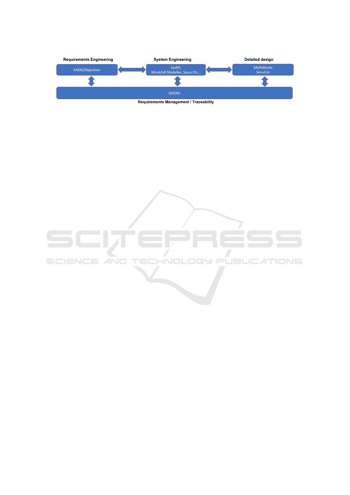
Figure 4: Toolchain used in the validation case.
method and tools but also to cover steps 1 to 3. It
was followed by a more global debriefing and con-
solidation phase to draw lessons and share them both
internally and with a wider industrial advisory board
for possible transfer in other domains. The main high-
lights are the following:
1. The Engineering Practices were actually gath-
ered with the system engineers. It revealed they
already used MBSE tools for system engineer-
ing. However, the available tooling was mainly
used to support the production of traditional docu-
ment (i.e. system/subsystem requirements, archi-
tecture, functional definition,...). A training phase
was also organised so the R&D team could get to
know to target system, the stakeholders and the
development methodology used, i.e. ASAP (Ad-
vanced System Architecture Program).
2. Objectives and Business Case were elaborated
by analysing the shortcomings of the existing sys-
tems and market trends. It was supported by the
elaboration of a strategic goal model.
3. The Global Strategy and Selection of Meth-
ods/Tools was a resource consuming step based
on the definition of criteria for identifying mod-
ernisation priorities and to drive the selection of
tools. This step was investigated in a wider con-
text for enabling a more general application. A
similar process was applied for the review of
MBSE methodologies using the FEMMP assess-
ment framework (Weilkiens et al., 2016). The
toolchain selected is depicted in Figure 4. It is
composed of three main modelling tools with the
ability to synchronise their models: Objectiver
for requirements engineering (Respect-IT, 2002)
using the KAOS methodology (van Lamsweerde,
2009), Integrity Modeler (PTC, 2020) for SysML
(OMG, 2005) and Simulink for the implementa-
tion (Mathworks, 2019).
4. Understanding the Current Software was per-
formed based on the knowledge acquired during a
series of workshops using the MBSE tooling. As-
is solution description were easy to find in docu-
ments and models in the project repository. The
trickiest part was to trace the design rationales
back to problem level. It required to rebuild a goal
model as partly shown in Figure 5.
5. The Target Architecture was build using PTC by
importing new requirements engineered using the
Objectiver tool but further refined in PTC as re-
quired. Figure 6 represents the target architecture
model. To-be requirements were also produced
but within the same model: high-level goals re-
mained unchanged and alternatives were identi-
fied at specific refinement levels to introduce new
design choices in a motivated and traceable way.
6. Detailed Strategy and Modernisation Plan. In
order to be able to integrate new components (in
the C language) inside the existing (legacy) Ada
application, a wrapping mechanism was defined.
The plan step was not elaborated as the PoC was
limited to a specifically identified increment.
7. Execution, Validation and Assessment. The
execution was performed by refining the design
in PTC and then transferring specification to
Simulink for their reimplementation in C as de-
picted in Figure 7. Code generation was used to
produced the required C code. The available test
suite could then be rerun with a 97% level of suc-
cess. The remaining problems could be traced
to modelling problems or wrapper problems and
fixed. The assessement step was performed with
both teams and is summarised in this paper.
4 SOME LESSONS LEARNED
First, the selection of a MBSE methodology to drive
the process is a prerequisite. If no methodology is
currently available, the FEMMP selection can be used
to identify the most adequate one for a given context
(Weilkiens et al., 2016). It is composed of about 30
questions covering important criteria such as the com-
pliance with SysML, tool support, vendor indepen-
dence, non-functional requirements, etc. In our case,
the ASAP methodology was in place but, through
FEMMP, we could check it was adequate.
Likewise, the selection of the toolchain can be
time consuming given several aspects to take into ac-
Towards Incremental Model-Driven Software Modernisation: Feedback from an Industrial Proof of Concept in Railways
657

Figure 5: Goal model of the current software systemh.
Figure 6: High-level SysML model.
Figure 7: Simulink model of a redesigned component.
ICSOFT 2023 - 18th International Conference on Software Technologies
658

count such as the ability to exchange models, generate
documents, support collaborative work, compliance
with certification, etc. It is difficult to rely on existing
surveys as they are usually quickly outdated given the
constant evolution of the tools, acquisition between
vendors and changes in integration protocols. The
volatility of the tooling is itself a part of the moderni-
sation problem and the toolchain itself should be con-
sidered part of the environment to secure and evolve.
The use of modelling has opened new doors, es-
pecially to go beyond the mere architectural refactor-
ing by reconnecting from the solution into the prob-
lem domain, enabling the modernisation process to
recover and re-engineer the requirements prior to the
work at the architecture level. This relies on an elic-
itation process sharing some similarities with a reim-
plementation process. Although this work can gener-
ate overhead in the first iteration, it can be kept under
control by making sure the scope stays closed to the
system being modernised (avoid modelling connected
systems beyond their interactions). They should also
be kept at the level of abstraction of the considered
systems and leave more technical requirements for the
architectural phase. As the process is iterative, the re-
quirements of specific subsystem can be investigated
in due time. Finally, provided the model is main-
tained, each iteration with rely on model of increasing
quality and require decreasing effort to build, provid-
ing more incentive to fully exploit it. Note also that all
iterations may not need deep reengineering and stay
at a more technical level. In this case the ”horseshoe”
curve depicted in Figure 2 is simply lower and require
less steps in the process to achieve.
5 CONCLUSION & NEXT STEPS
In this paper, we proposed a methodology for driv-
ing the modernisation of software intensive systems
in an incremental way by progressively bridging the
gap between the as-is and to-be situations through
a model-based (MBSE) approach. We validated the
feasibility of the approach on a proof-of-concept case
focusing on a specific functionality of a railway com-
ponent. The rich set of models allowed us to go be-
yond pure technical and architectural considerations
and reason on the gap at problem level. On the other
side, it was also possible to extend the use of mod-
els down to the implementation using code generation
and efficiently requalify the modernised component
through automated testing with few issues to fix.
Although encouraging, this validation is still lim-
ited in scope and a number of improvements have
been identified as future work. The increment gran-
ularity needs to be assessed based on the cost vs time
to issue a milestone vs the global modernisation time.
A number of internal and external dependencies may
also need to be integrated in the project, e.g. the deci-
sion to migrate to a new technology or language. On
the tooling side, the need of reliable connectors across
the toolchain and of a global versioning system was
identified.
REFERENCES
Comella-Dorda et al. (2000). A survey of black-box mod-
ernization approaches for information systems. In
Proc. Int. Conf. on Software Maintenance.
Holladay, J. B. et al. (2019). Mbse infusion and modern-
ization initiative (miami): ”hot” benefits for real nasa
applications. In 2019 IEEE Aerospace Conference.
Johnson, J. and Mulder, H. (2021). Endless moderniza-
tion: How infinite flow keeps software fresh. Standish
Group.
Khadka, R. et al. (2015). Does software modernization de-
liver what it aimed for? a post modernization analysis
of five software modernization case studies. In 2015
IEEE International Conference on Software Mainte-
nance and Evolution (ICSME), pages 477–486.
Mathworks (2019). Simulink v10.
www.mathworks.com/products/simulink.html.
Morkevicius, A., Bisikirskiene, L., and Jankevicius, N.
(2016). We Choose MBSE: What’s Next? Complex
Systems Design & Management.
OMG (2005). System modeling language. http://www.omg.
org/spec/SysML.
OMG (2016). Architecture driven modernization. https:
//www.omg.org/adm.
PTC (2020). Windchill modeller v12.
www.ptc.com/fr/products/windchill/modeler.
Respect-IT (2002). Objectiver- goal-oriented requirements
engineering toolset. www.objectiver.com.
Santos, B. M. et al. (2018). Software refactoring for system
modernization. IEEE Software, 35.
Stavru, S., Krasteva, I., and Ilieva, S. (2013). Challenges
of model-driven modernization: An agile perspective.
Proc. of the 1st Int. Conf. on Model-Driven Engineer-
ing and Software Development.
van Lamsweerde, A. (2009). Requirements Engineering -
From System Goals to UML Models to Software Spec-
ifications. Wiley.
Weilkiens, T., Scheithauer, A., Di Maio, M., and Klusmann,
N. (2016). Evaluating and comparing mbse method-
ologies for practitioners. In IEEE International Sym-
posium on Systems Engineering (ISSE).
William M. Ulrich, P. N. (2010). Information Systems
Transformation: Architecture-Driven Modernization
Case Studies. Morgan Kaufmann.
Towards Incremental Model-Driven Software Modernisation: Feedback from an Industrial Proof of Concept in Railways
659
