
Design and Simulation for Disk-Type Magnetorheological Fluid
Transmission Device
Lifeng Wang, Yiwei Zhang
*
, Juan Yan and Chuanjiang Li
College of Mechanical Engineering, Chongqing Three Gorges University, Chongqing, China
Keywords: Magnetorheological Fluid, Transmission Device, Mechanism Analysis, Magnetic Circuit Simulation.
Abstract: The magnetorheological fluidtransmission device (MRTD) are chosen as study object for few mature
magnetorheological fluid devices. Firstly, the working principle of MRTD introduced and a disk-type MRTD
is designed based on the magneto-rheological Bingham model. Secondly, the magnetic circuit of MRTD is
designed and the magnetic circuit materials in the device are selected. Finally, the magnetic circuit simulation
are carried out based on finite element analysis software Ansoft Maxwell, thus, the distributions cloud picture
of magnetic field under different excitation currents are obtained.The designed MRTD is able to meet the
working requirements and provides reference and basis for optimal design of magnetorheological fluid
devices.
1 INTRODUCTION
Magnetorheological fluids (MRF) are composed of
micron sized ferromagnetic particles and additives
with modification function dispersed in the carrier
liquid to form a suspension system (Wang, 2015; (Liu,
2013; Cvek, 2020). This system can produce obvious
magnetorheological effect under the action of
magnetic field. When there is no external magnetic
field, it behaves as Newtonian fluid state. When the
external magnetic field is applied, the internal
magnetic particles will form chains along the
direction of the magnetic field within a few
milliseconds, changing from a liquid state to a solid-
like state, showing controllable shear yield strength
(Zhu, 2020). As such transformation is reversible,
rapid and controllable, MRF has been increasingly
applied in automotive brakes, clutches, dampers,
medical instruments, aerospace and other fields
(Desai, 2020; Kim, 2018).
The magnetorheological fluid transmission
device (MRTD) has attracted extensive attention from
scholars at home and abroad because of its simple
control, low energy consumption and short response
time. Since Lord Company developed the first
magnetorheological fluid brake in 1997, the
transmission device has been studied deeply in
foreign countries, and a series of achievements have
been made. Gopalswamy (Gopalswamy, 1998) of
General Motors in the United States successfully
developed the magnetorheological fluid clutch.
Kavlicoglu (GopKavlicoglu, 2007) from University
of Nevada studied the response time and performance
of the magnetorheological fluid limited slip clutch.of
MRF limited slip differential clutch of response time
and performance are analyzed. Great progress has
also been made in the study of magnetic transmission
in China. Meng Weijia (Meng, 2022) carried out the
structural design and simulation experiment of the
double-plate magnetorheological fluid clutch. Guo
Jiangchuan (Guo, 2022) studied the influence of
current, clearance and speed difference on the
transmission performance of magnetorheological
fluid clutch through experiments. Li Xing (Li, 2011)
designed a disc-type magnetorheological soft starting
device and optimized its structural parameters
through magnetic field simulation analysis.
There are many patents related to MRTD or
continuously variable speed device, but there are few
mature products. In this paper, a disc MRTD is
designed, of which the magnetic field are analyzed
and simulated. Magnetic circuit design of MRTD is
verified by magnetic flux density test-bed.
Wang, L., Zhang, Y., Yan, J. and Li, C.
Design and Simulation for Disk-type Magnetorheological Fluid Transmission Device.
DOI: 10.5220/0012142400003562
In Proceedings of the 1st International Conference on Data Processing, Control and Simulation (ICDPCS 2023), pages 23-27
ISBN: 978-989-758-675-0
Copyright
c
2023 by SCITEPRESS – Science and Technology Publications, Lda. Under CC license (CC BY-NC-ND 4.0)
23
2 MECHANISM ANALYSIS OF
MRTD
2.1 Working Principle of MRTD
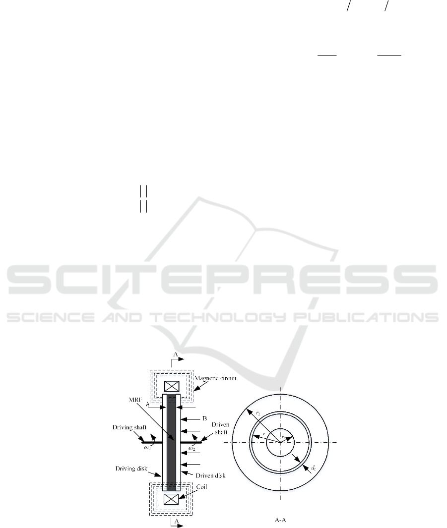
The working principle of the MRTD is shown in
Figure 1. The driving and driven disks are filled with
magnetorheological fluid and placed in a controllable
magnetic field B. The magnetic field direction is
along the axial direction of the device. Different
magnetic field strengths are obtained by adjusting the
size of the excitation current. The MRF will produce
corresponding rheological effects and can transfer a
certain amount of torque.
Under the action of magnetic field, the
constitutive equation of MRF can be described by
Bingham model, and its expression can be calculated
as follows:
0
00
0
)sgn()(
ττγ
ττηγγττ
<=
≥+= B
Where τ is the shear stress generated by MRF, τ
0
is the yield stress of MRF, γ is the shear stress of MRF
and η is the viscosity coefficient of MRF. In the figure
1, r
1
and r
2
are the inner diameter and outer diameter
of the driving and driven disks respectively. Take a
micro ring with a radial width of d
r
on the disk with a
radius of r, then the micro torque transmitted by MRF
on the micro ring surface can be expressed as follows:
drrdT
2
2
πτ
⋅=
Assume that the speed of the driving disk and
driven disk is ω
1
and ω
2
respectively. The shear
stressγcan be calculated as follows:
12
()=rhrh
γ
ωω ω
=- Δ
From this, it can be concluded that the torque
transmitted by MRTD in the working area is:
)(
2
)(
3
2
2
4
1
4
2
3
1
3
2
0
2
2
1
rr
h
rrdrrT
r
r
−
Δ
+−=⋅=
ω
π
η
π
τ
πτ
2.2 Structure Design of MRTD
The designed MRTD is shown in Figure 2. MRTD is
composed of 1- housing, 2-yoke, 3-coil, 4-magnetic
separator ring, 5-driving disk, 6-bearing seat, 7-
bearing, 8-nut, 9-input shaft, 10-oil seal, 11- driven
disk, 12-hexagon socket bolt and 13-driven disk. The
power is input from the driving shaft, the driving disk
is fixedly connected with the driving shaft, and the
driven disk is fixedly connected with the driven shaft.
MRF is filled between the driving and driven disks,
which is sealed by the fluorine rubber oil seal with
high temperature resistance and good wear resistance.
When the current is applied to the excitation coil, the
working gap between the driving and driven disks
produces a magnetic field, and MRF has a rheological
effect. The power is transferred to the driven disk
through MRF, and then output through the driven
shaft. The torque can be adjusted by controlling the
input current of different excitation coils.
Figure 1: Working principle diagram of MRTD.
ICDPCS 2023 - The International Conference on Data Processing, Control and Simulation
24
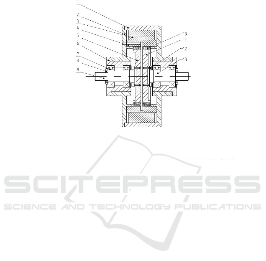
Figure 2: Working principle diagram.
3 MAGNETIC CIRCUIT
ANALYZE AND SIMULATION
OF MRTD
3.1 Magnetic Circuit Design of MRTD
The experiment and research show that the shear
stress formed when the magnetic line of force passes
through the shear direction of MRF vertically is much
greater than that formed when the magnetic line of
force passes through the shear direction of MRF in
parallel. Therefore, the magnetic circuit design has a
crucial influence on the torque that can be transmitted
by the magnetorheological fluid transmission device.
When designing the magnetic circuit, ensure that the
magnetic force line passes through the working gap
formed by the driving and driven disks vertically.
Magnetoresistance is a parameter in the
magnetic circuit of MRTD. Applying current to the
excitation coil can generate magnetic field in the
working area, but when the magnetic flux passes
through the gap in the magnetic circuit, the magnetic
flux density will decrease, because a part of the
magnetic flux is lost in the non gap, forming magnetic
leakage, which leads to the formation of magnetic
resistance in the magnetic circuit. According to Ohm's
law of magnetic circuit, the magnetic resistance of
magnetic circuit is expressed as:
m
m
F
NI L
R
A
ΦΦ
μ
===
Where R
m
is magnetic circuit magnetoresistance
(H
-1
), F
m
is magnetomotive force (A), Φ is magnetic
flux (Wb), N is total coil turns, I is excitation coil
current (A), L is magnetic circuit length (m), μ Is the
magnetic permeability (H/m), and A is the sectional
plane perpendicular to the magnetic line of force (m
2
).
According to the above formula, in order to
reduce the magnetic resistance of the magnetic circuit,
materials with high permeability should be selected
when designing the magnetic circuit of the device.
Permeability reflects the transfer ability of materials
to magnetic lines of force. When designing the
magnetic circuit, materials with high magnetic
permeability should be selected, so that when the
excitation current and the number of winding turns
are the same, the MRF placed in the working gap can
obtain greater magnetic field strength. The drive
device uses a coil with a certain number of turns as
the magnetic field generator, which is used to meet
the required magnetic field strength in the working
area. The selection and design of excitation coil
mainly consider the parameters such as heat loss,
material, wire diameter and turns.
Design and Simulation for Disk-type Magnetorheological Fluid Transmission Device
25

Table 1: Selection of magnetic conductive materials for main parts.
Part Yoke Driving and driven disks Magnetic separator ring Coil
Material 20#steel 20#steel Aluminium Copper wire
3.2 Selection of Magnetic Circuit
Materials
The selection of magnetic circuit materials has a great
influence on the magnetic field strength obtained in
the working gap of MRTD. Compared with materials
with smaller permeability, materials with higher
permeability can produce larger magnetic field
strength when the excitation current is smaller. Under
the same excitation current conditions, materials with
higher permeability can obtain greater magnetic field
strength, thereby increasing the transmission torque
of the transmission device. The material selection of
the main parts of MRTD is shown in Table 1.
3.3 Magnetic Circuit Simulation of
MRTD
The magnetic circuit design method is usually to
convert or transfer the energy to the closed loop of
limited magnetic flux designed by engineers, which is
assumed to be linear when calculating the magnetic
permeability of materials. This design method adopts
a simple approximate calculation method, which
easily ignores the influence of magnetoresistance,
magnetic leakage, saturation magnetization effect and
material nonlinearity. Therefore, Ansoft Maxwell is
selected for magnetic field design and numerical
simulation. Starting from the essential characteristics
of ferromagnetic materials, the simulation can
accurately obtain the magnetic field distribution of the
device. The steps of Maxwell3D magnetic field
simulation based on Ansoft software are as follows:
establishing and simplifying geometric models,
simplifying the import of geometric models, defining
material properties, selecting magnetic field analysis
mode, specifying boundary conditions, loading
current excitation, setting solution options, numerical
analysis and post-processing, etc.
Figure 3: Distribution of magnetic flux density under different current.
ICDPCS 2023 - The International Conference on Data Processing, Control and Simulation
26

The number of turns of the excitation coil of MRTD
designed in this paper is 1500 and the clearance
between the master and slave discs is 2mm.When the
excitation current is 0.5A, 1A, 2A, 3A, the magnetic
induction intensity distribution cloud diagram of the
working gap inside the device is shown in figure 3.
When the excitation current is 0.5A, the magnetic
induction intensity distribution cloud diagram of the
working gap is shown in figure 3(a), and the average
magnetic field is about 0.22T. When the excitation
current is 1A, the magnetic induction intensity
distribution cloud diagram of the working gap is
shown in figure 3(b), and the average magnetic field
is about 0.25T. When the excitation current is 2A, the
magnetic induction intensity distribution cloud
diagram of the working gap is shown in figure 3(c),
and the average magnetic field is about 0.38T. When
the excitation current is 3A, the magnetic induction
intensity distribution cloud diagram of the working
gap is shown in figure 3(d), and the average magnetic
field is about 0.62T. At the same time, it can be seen
that the magnetic field distribution in the working area
at the working clearance of the transmission device is
more uniform; When the number of turns of the
excitation coil is a fixed value, the magnetic field
strength in the working area increases with the
increase of the excitation current; When the excitation
current is 3A, the magnetic induction can reach 0.62T,
which meets the requirements of experimental
research.
4 CONCLUSION
In order to promote the development of
magnetorheological fluid devices, a disk-type MRTD
is designed, of which the magnetic field are analyzed
and simulated. The simulation results show that the
magnetic field distribution in the working area of
MRTD is uniform. When the excitation current is 3A,
the average magnetic field strength in the working
area is 0.62T, meeting the design requirements. The
research in this paper can provide reference and basis
for the optimization design of high-power MRTD.
ACKNOWLEDGMENTS
This work is supported by Science and Technology
Research Project of Chongqing Education
Commission (KJQN202001208, KJQN202201241,
KJQN202001211).
CONFLICTS OF INTEREST
The authors confirm that this article content has no
conflict of interest.
REFERENCES
Wang Lifeng, Liu Xinhua, Zhang Qiuxiang, et al. A Study
about the Influence of Some New Additives Addition
on the Properties of Magnetorheological Fluids. Recent
Patents on Materials Science, 2015, 8(1):74-80(7).
Liu Xinhua, Liu Yongzhi, Liu Hao. Magnetorheological
fluids particles simulation through integration of
Monte Carlo method and GPU accelerated technology.
CMES: Computer Modeling in Engineering &
Sciences, 2013, 91(1): 65-80.
M. Cvek, R. Torres-Mendieta, O. Havelka, M. Urbanek, T.
Plachy, and M. Cernik, “Laser-induced fragmentation
of carbonyl iron as a clean method to enhance
magnetorheological effect,” Journal of Cleaner
Production, vol. 254, p. 120182, 2020.
W. Zhu, X. Dong, H. Huang, and M. Qi, “Enhanced
magnetorheological effect and sedimentation stability
of bimodal magnetorheological flfluids doped with
iron nanoparticles,” Journal of Intelligent Material
Systems and Structures, 2020.
R. Desai, S. Acharya, M. Jamadar et al., “Synthesis of
magnetorheological fluid and its application in a twin-
tube valve mode automotive damper,” Proceedings of
the Institution of Mechanical Engineers, Part L, vol.
234, no. 7, pp. 1001-1016, 2020.
B. Kim, J. Chung, M. Cho, and G.-S. Yoon,
“Magnetorheological fluid polishing using an
electromagnet with straight pole-piece for improving
material removal rate,” Journal of Mechanical Science
and Technology, vol. 32, no. 4, pp. 3345–3350, 2018.
Gopalswamy S, Linzell S M, Jones G L, et al. MR Fluid
Clutch with Minimized Reluctance: US, 5896965.
1998 – 12- 08.
GopKavlicoglu N C, Kavlicoglu B M, Liu Y, et al. Response
time and Performance of a High -torque Magneto -
rheological Fluid Limited Slip Differential Clutch.
Smart Materials and Structures, 2007, 16( 1):149-159.
Meng Weijia. The study and design of double-plates MRF
clutch. Harbin Institute of Technology
Guo Jiangchuan. Theoretical and experimental research on
magnetorheological fluid transmission. South China
University of Technology.
Li Xing, Fan Yuanxun, Peng Wengang, Design and
optimization of magnetorheological soft starting device.
Mechanical Engineering & Automation, 2011,(4):78-80.
Design and Simulation for Disk-type Magnetorheological Fluid Transmission Device
27
