
Criticality Safety Calculation and Analysis for NPP Transportation of
Fuel Assemblies
Dajie Zhuang
China Institute for Radiation Protection, Taiyuan, 030006, China
Keywords: Criticality Safety, Benchmark Certification, LEU (Low-Enriched Uranium), Rods Lattice.
Abstract: Nuclear criticality safety was calculated by MC code for transportation activity of fuel assemblies to
Sanmen Nuclear Power Plant. Calculation result shows that the transportation of fuel assemblies meets the
corresponding criticality safety requirements. In the calculation, eight criticality benchmark experiments for
Low-Enriched Uranium rods lattice from NUREG/CR-6361 of the U.S. NRC was selected, and was
validated calculation by SuperMC. Thereby, the result of criticality calculation for transportation of fuel
assemblies with SuperMC code becomes more reliable.
1 INTRODUCTION
Nuclear criticality safety is an important issue in the
storage and transportation of fissile materials.
Regulations for the Safe Transport of Radioactive
Material
(GB11806-2019) has clear requirements for
nuclear criticality safety in the transportation of
fissile materials, such as fuel assemblies, etc. The
IAEA SSR6 also provides a detailed introduction to
the criticality safety assessment, including the
criticality safety analysis model, method, calculation
and experiments (SSG, 2012).
The Monte Carlo method can better model the
geometric structure in the criticality safety analysis
and is widely used. However, when using the MC
program to calculate the criticality safety, various
uncertainties must be considered to give the bias of
the program, such as model size, fuel enrichment,
section data, calculation method, etc. (LI, 2019) In
addition, since it is necessary to model and write
input files when using MC program for criticality
safety calculation, the calculation results of the
program may vary from person to person. Therefore,
when using the MC program for critical safety
calculation, the bias of the program must be
determined first.
2 CALCULATION PROGRAM
AND DETERMINATION OF
SUBCRITICAL LIMIT
2.1 Calculation Program
This project is supported by Super Monte Carlo
Program for Nuclear and Radiation Simulation,
named SuperMC, which is developed by Institute of
Nuclear Energy Safety Technology, Chinese
Academy of Science/the FDS Team. SuperMC is a
general, intelligent, accurate and precise simulation
software system for the nuclear design and safety
evaluation of nuclear system (WU, 2009; WU, 2015).
2.2 Subcriticality Benchmark
Experiment and Simulation
Calculation
This paper selects a group of eight subcriticality
benchmark experiments in Criticality Benchmark
Guide for Light-Water-Reactor Fuel in
Transportation and Storage Packages (NUREG/
CR-6361) (Lichtenwalter, 1997) of the US Nuclear
Regulatory Commission, and Dissolution and
Storage Experimental Program with UO
2
Rods
(Manaranche, 1979), which are ANS33AL1,
ANS33AL3, ANS33EB1, ANS33EB2, ANS33EP1,
ANS33EP2, ANS33SLG and ANS33STY
respectively. Fuel assembly dimensions, fuel rod
characteristics, material parameters and criticality
data are described in detail in the literature.
Zhuang, D.
Criticality Safety Calculation and Analysis for NPP Transportation of Fuel Assemblies.
DOI: 10.5220/0012145900003562
In Proceedings of the 1st International Conference on Data Processing, Control and Simulation (ICDPCS 2023), pages 51-57
ISBN: 978-989-758-675-0
Copyright
c
2023 by SCITEPRESS – Science and Technology Publications, Lda. Under CC license (CC BY-NC-ND 4.0)
51

Table 1: Simulation Results of Subcriticality Benchmark Test by SuperMC.
Subcriticalit
y
benchmark experimen
t
k
eff
±σ
ANS33AL1 1.00071±0.00186
ANS33AL3 0.99958±0.00169
ANS33EB1 0.99835±0.00173
ANS33EB2 1.00496±0.00162
ANS33EP1 1.00121±0.00180
ANS33EP2 0.99939±0.00183
ANS33SLG 0.99769±0.00166
ANS33STY 0.99510±0.00169
For fuel rods, the bottom end plug is simulated
as an aluminum cylinder with a diameter of 0.94 cm
and the top plug is 1.3 cm. The spring is not
simulated but replaced by air. The stainless steel fuel
grid with a thickness of 0.25cm at the bottom is also
not considered.
Use SuperMC to calculate these criticality
benchmark models, and the calculation results are
listed in Table 1. The cross section data used in the
program calculation is mainly from the endf60
continuous energy neutron cross section library, and
250 iterations are used in the program calculation,
and the results of the first 50 iterations with poor
statistics are omitted. The average value of the
results of the last 200 iterations is used, and the
number of particles simulated in each iteration is
1000.
2.3 Analysis of Simulation Results
The simulation results of the eight critical
benchmark experiments using SuperMC program are
very close to the test results, and more close to the
critical value 1.0, with the maximum deviation of
0.496% and the minimum deviation of 0.042%. It
can be seen from Table 1 that the average deviation
b and the calculated standard deviation
σ
of the
SuperMC program for the calculated value of the
critical benchmark simulation are:
00210.0
8
1
9
1
)(
≈
−
=
=i
ieff
k
b
(1)
()
00272.0
8
1
9
1
2
)(
≈
−
=
=i
ieff
k
σ
(2)
Then consider various uncertainties of the
program (including fuel enrichment, model geometry,
material cross-section data, experimental data,
calculation methods, etc.), conservatively add 3
times of the standard deviation
σ
to the above
average deviation b , that is, the bias of the
SuperMC program
b
σ
is
3010.03 ≈+=
σσ
b
b
(3)
3 NUCLEAR CRITICALITY
SAFETY CALCULATION FOR
FUEL ASSEMBLY
TRANSPORTATION
3.1 Description of Transport Container
The shape of PWR fuel assembly transport container
is a tubular structure, mainly including two parts:
outer cylinder and inner cylinder. The structure is
shown in Figure 1.
(1) Outer cylinder
The outer cylinder consists of an upper cover and
a base. It is a "steel foam plastic steel" laminated
structure composed of an austenitic stainless steel
shell, an inner shell and a rigid polyurethane foam
plastic between two shells. The upper cover can be
opened or removed, and the base is fixed on a
forklift bracket. The base of the outer cylinder is
connected with the hinges on both sides by 24
hexagon bolts, and the upper cover is also connected
with the hinges by 24 bolts. When all 48 bolts are
fastened, the upper cover and base are fixed together.
When the 12 bolts connecting the upper cover and
hinge on one side are removed, the upper cover
connected through the hinge on the other side can be
just like a door. Acrylic glass fiber sealing gasket is
set between the joint surface of upper cover and base
to prevent rainwater from entering the package.
There is no pressure seal design between the
transport container package and the surrounding
environment, so there will be no differential pressure
in the package.
ICDPCS 2023 - The International Conference on Data Processing, Control and Simulation
52
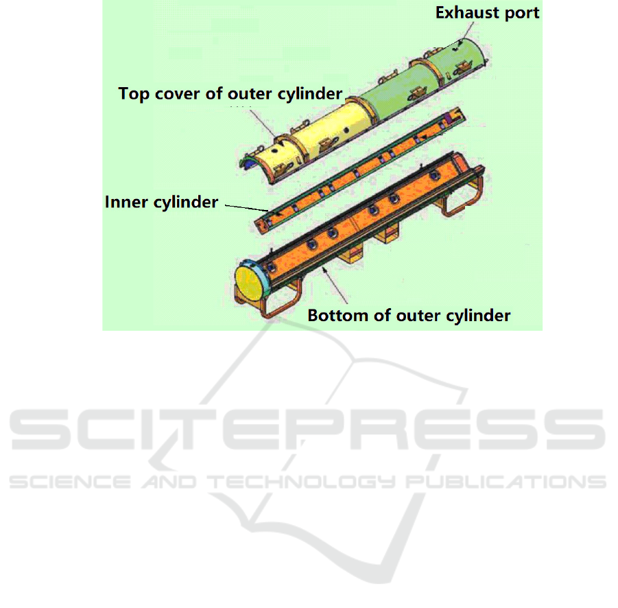
Figure 1: Fuel Assembly Shipping Container Component Drawing.
The outer shell of the outer cylinder is used to bear
the structural strength of the container, and the lower
part is designed with a forklift platform to lift, stack
and tie down the container during transportation;
The foam plastic of the outer cylinder interlayer is
used for heat insulation and impact protection. Some
polyethylene blocks are attached to the inner shell of
the outer cylinder for critical safety; The two ends of
the outer cylinder are equipped with shock absorbers,
which are made of 20 pcf polyurethane foam
covered with stainless steel leather.
(2) Inner Cylinder
The inner cylinder is a rectangular box composed
of an aluminum V-shaped positioning plate, two
aluminum plate doors, bottom and top plates, and a
multi-point cam hinge and latch device. It plays the
role of protecting the built-in fuel assembly
structurally; The V-shaped locating plate and two
aluminum doors are connected by continuous (11
cams) hinges. One aluminum door is equipped with
a cam lock plate, which is locked with the other door
by turning at right angles; The fixing structure of the
top plate of the inner cylinder and the inner cylinder
wall is designed with flat head hexagon hole screws,
nuts and recessed seams. The bottom plate is also
fixed to the inner cylinder through screws, and can
be closed by connecting the nut and groove with the
inner shell door. The inner surface of the inner
cylinder is attached with a neutron absorption plate,
which is installed on the inner surface along the full
length of the four sides of the inner cylinder and is
fixed on the inner wall with threaded fasteners.
The inner cylinder is also a part of the container
restraint system, which can protect and constrain the
fuel assembly under different transportation
conditions. A rubber pad is set on the inner axial
position of the inner cylinder door to constrain the
lateral movement of the assembly. The top of the
inner cylinder is equipped with an adjustable thread
clamping component, which can provide the top
axial restraint for the fuel assembly or the rod tube.
When the fuel assembly is placed in it, additional
restraint devices are added to fix it.
3.2 Fuel Assembly
PWR new fuel assembly consists of the fuel rod and
fuel assembly skeleton arranged in a 17×17 square
shape. The fuel assembly skeleton comprises an
upper tube socket, a lower tube socket, a grid, a
guide tube and a neutron flux measuring tube. Each
fuel assembly consists of 289 grid cells, 24 of which
are occupied by the guide tube, one by the neutron
flux measuring tube, and the remaining 264 are
loaded into the fuel rod or the overall burnable
poison rod. The fuel rod is loaded into the fuel
assembly framework and clamped by the grid to
keep it at the specified axial and radial positions, and
the fuel rod is allowed to expand freely along the
axial direction. Sufficient clearance shall be reserved
between the end of fuel rod and upper and lower
tube sockets to compensate for different thermal
Criticality Safety Calculation and Analysis for NPP Transportation of Fuel Assemblies
53

expansion and irradiation growth between fuel rod
and guide tube. When the fuel assembly is loaded
into the core, it is assembled by the locating hole on
the lower tube socket and the locating pin on the
lower plate of the core to make it stand upright in the
core. When the upper core plate is in place, press
down the four groups of plate compression springs
of the upper tube socket to provide enough
compression force to position the fuel assembly on
the designated position of the core, and it will not
move upward under hydraulic scouring. The axial
load applied on the fuel assembly and the weight of
the fuel assembly are transferred to the lower plate
of the core through the guide tube and the lower tube
socket; The lateral load applied to the fuel assembly
is transferred to the core support structure through
the locating pins on the upper and lower core plates.
See Table 2 for specific parameters.
3.3 Criticality Calculation Model
The calculation model includes two models: single
package and infinite package array. Some
conservative assumptions were adopted in the
establishment of the critical safety calculation model,
and the following conditions were mainly considered
in the calculation:
(1) Under normal transportation conditions, there
will be no water in the transport container;
(2) Under accident conditions, all the spaces
inside the transport container are filled with water;
(3) The maximum 235U enrichment of fuel for
shipment is 5% and UO2 density is 10.96 g/cm3;
(4) A 30 cm thick water reflecting layer is falsely
set outside the transport container;
(5) The neutron poison plate is modeled
according to 75% of the actual density of boron
aluminum material, 1.942 g/cm3;
Table 2: Main parameters of fuel assembly.
component Main parameters
Fuel pellet
Material Uranium dioxide ceramics
Maximum
235
U enrichment(%) 4.80
Diameter (mm)
Outer diameter (mm) 8.19
inner diameter (mm) 3.94
Length(mm)
Normal pellet 9.83
Axial regeneration zone pellet 12.70
Pellet density(g/cm
3
) 10.41
Fuel rod
Cladding material ZIRLO
Rod length(mm) 4583.20
Outer diameter (mm) 9.50
Cladding wall thickness(mm) 0.57
Fuel
assembly
Arrangement form 17×17 square
Number of cells 289.00
Number of fuel rods 264.00
Fuel rod center distance (mm) 12.60
Transverse overall dimension (mm) 213.97×213.97
Total length of assembly (mm) 4798.70
Height of active segment (mm) 4267.20
Total weight of single component (kg) 794
Metal uranium weight of single component (kg) 541
ICDPCS 2023 - The International Conference on Data Processing, Control and Simulation
54

Table 3: Main materials and parameters.
Material Chemical composition and correspondin
g
atomic densit
y
(10
24
/cm
3
) densit
y
(
g
/cm
3
)
UO
2
U-238( 2.32E-2) U-235(1.24E-3) O(4.89E-2) 10.96
Wate
r
H(6.68E-2) O(3.34E-2) 1.00
Boron aluminum
material
B-10(4.78E-3) B-11(1.94E-2) C(6.04E-3) AL(4.32E-2) 2.59
Pol
y
eth
y
lene C(3.95E-2) H(7.91E-2) 0.92
Foa
m
O(9.65E-4 H(9.57E-3) O(5.63E-3) N(2.76E-4) 0.16
Al 100% 2.70
Fe 100% 7.94
Z
r
100% 6.56
F
igure 2: Model of single package under normal and accident
conditions.
Figure 3: Cross section of 151
p
acka
g
es arra
y
.
(6) The polyethylene material is modeled
according to 90% of the actual density, 0.828 g/cm3;
(7) In order to simplify the calculation model,
the positioning grid, upper and lower tube sockets
and damping frame are not considered in the fuel
assembly.
The main materials and corresponding
parameters used in the model are listed in Table 3.
Under normal and accident conditions established by
SuperMC, when the outermost layer of the package
is set as specular reflection. The section of the
calculation model is shown in Figure 3.
3.4 Calculation Results and Analysis
The calculation results are listed in Table 4.
Since the enrichment of
235
U in the simulated
fuel rod UO
2
pellet is 5%, the actual enrichment is
less than 4.8%, the UO
2
density selected for
calculation is conservative. It can be seen from Table
4 that under accident conditions, the keff value of the
infinite cargo package array first decreases, then
increases, and then decreases with the decrease of
water density. When the water density is 1.0 g/cm
3
,
the keff has a maximum value.
4 CONCLUSION
In this paper, the Monte Carlo software SuperMC is
used to analyze the critical safety performance of
new fuel transportation containers under normal
transportation conditions and transportation
accidents. Based on the characteristics of new fuel
and possible accident scenarios, eight benchmark
test cases that meet the requirements are selected for
verification. According to the statistical analysis of
benchmark test calculation results, the bias of the
SuperMC is 0.0103.
For a single package, water will not enter the
package under normal transportation conditions, and
the maximum k
eff
value after considering 3 times of
standard deviation and the standard deviation of the
critical calculation program is 0.22733; The
maximum k
eff
value of water entering the internal
clearance of the cargo package under accident
conditions is 0.85,704 after considering 3 times of
the standard deviation and the standard deviation of
the critical calculation program, which belongs to
subcritical.
Criticality Safety Calculation and Analysis for NPP Transportation of Fuel Assemblies
55

Table 4: The calculation case and results of criticality safety.
Calculation conditions
Water density
(g/cm
3
)
k
eff
σ k
eff
+3σ
k
eff
+3σ+
b
σ
Normal conditions of single
package
1.0
0.2159 0.00039 0.21707 0.22733
Accident conditions of single
package
1.0
0.84414 0.00088 0.84678 0.85704
Normal conditions of unlimited
package array
1.0
0.27262 0.00049 0.27409 0.28435
Unlimited package array accident
conditions
1 0.89921 0.00088 0.90185 0.91211
0.995 0.89678 0.00084 0.8993 0.90956
0.99 0.89381 0.00084 0.89633 0.90659
0.98 0.88681 0.00079 0.88918 0.89944
0.97 0.88395 0.00078 0.88629 0.89655
0.96 0.87901 0.00086 0.88158 0.89184
0.95 0.87456 0.00095 0.87741 0.88767
0.94 0.86960 0.00078 0.87194 0.8822
0.93 0.86550 0.0008 0.8679 0.87816
0.92 0.86103 0.00082 0.86346 0.87372
0.91 0.85311 0.00079 0.85547 0.86573
0.9 0.84866 0.00087 0.85127 0.86153
0.8 0.79102 0.00083 0.79351 0.80377
0.7 0.72706 0.00084 0.72958 0.73984
0.6 0.65704 0.00085 0.65959 0.66985
0.5 0.58353 0.00079 0.5859 0.59616
0.4 0.50542 0.00071 0.50755 0.51781
0.3 0.43179 0.00057 0.4335 0.44376
0.2 0.37139 0.00053 0.37298 0.38324
0.1 0.33845 0.0005 0.33995 0.35021
Under normal transportation conditions of 151 cargo
bag arrays, the value of k
eff
is 0.28435, Under
accident conditions k
eff
is 0.91211, which both are
lower than 0.95,the limit of allowed by regulations.
Nuclear criticality safety of new fuel assembly
transportation activities is guaranteed.
REFERENCES
GB 11806—2019, Regulations for the Safe Transport of
Radioactive Material.
SSG 26—2012, Advisory Material for the IAEA
Regulations for the Safe Transport of Radioactive
Material.
LI Ying-hong, HUANG Hao, ZHOU Rong-sheng, et al.
Criticality Safety Calculation and Analysis of Fresh
Fuel Element Transport Containers for High
Temperature Gas-Cooled Reactor. Nuclear Power
Engineering, 2019, 40(6): 64-71.
WU Y, FDS T. CAD-Based Interface Program for Fusion
Neutron Transport Simulation, Fusion Energy Design,
2009, 84: 1987-1992.
WU Y J, SONG H, ZHENG, et al. CAD-Based
MonterCarlo Program for Intergrated Simulation of
Nuclear System SuperMC, Annals Nuclear Energy,
2015, 82:161-168.
Lichtenwalter J. J., Bowman S. M., Dehart M. D., et al.
ICDPCS 2023 - The International Conference on Data Processing, Control and Simulation
56

Criticality benchmark guide for Light-Water-Reactor
fuel in transportation and storage packages.
NUREG/CR-6361 ORNL/TM-13211. U.S. Nuclear
Regulatory Commission. 1997.
Manaranche J. C., Mangin D., Maubert L. et al.
Dissolution and storage experimental program with
UO2 rods. Tran. Am. Nucl. Soc., 1979. 33: 362-364.
Criticality Safety Calculation and Analysis for NPP Transportation of Fuel Assemblies
57
