
Network Structure Identification for Medium Transport in a Virtual
Reality Environment
Linh Tuan Mai
a
and Heiko Werdin
Chair of Building Energy Services, Faculty of Mechanical Engineering,
University of Applied Sciences Dresden, Dresden, Germany
Keywords:
Building Energy Service Simulation, Virtual Reality, Smart Education.
Abstract:
Building Information Modelling (BIM) in the Architecture, Engineering, and Construction(AEC) sector al-
lows for significant improvements in working efficiency throughout the entire life cycle of a building and has
become mandatory in many countries. This process necessitates a greater understanding of the entire system
from engineers, technicians, and facility managers, resulting in a greater demand for appropriate educational
methods involving system simulation. The simulation of building energy services includes determining the
network structure for medium transport, which is often not included in the BIM-model. This paper describes a
workflow for determining the structure of a component-based geometrical model of a building energy service
involving medium transport automatically. The workflow can be divided into three stages: identifying con-
nected components, determining valid connection paths from a starting point to an end point, and determining
the initialized flow direction of the transport medium within the system as well as the network structure. The
depicted solution includes the workflow’s implementation and integration into a virtual reality environment
for educational purposes. This approach has been validated through various exemplary generated test systems
and allows for the realization of flexible educational use cases.
1 INTRODUCTION
1.1 Simulation as Tool for a Better
Understanding of Building Energy
Services
Building energy services (BES) include technical sys-
tems in a building, such as shading, heating, cool-
ing, ventilation, and air conditioning (HVAC), and are
responsible for creating a suitable living and work-
ing environment for its residents (Hall and Greeno,
2017). BES are an important component of any mod-
ern building, contributing significantly to the fulfill-
ment of requirements for user comfort and the overall
energy efficiency of the structure.
Different building usages necessitate different
BES, ranging from simple BES in an apartment build-
ing to much more complex BES in functional build-
ings. The number of components (e.g., radiators,
pumps, pipes, air ducts) as well as the dimension and
specific component types vary between BES. The be-
haviors of different BES differ accordingly, resulting
a
https://orcid.org/0000-0001-8265-534X
in increased demand for experts (technicians, engi-
neers, and facility managers) in this domain with ex-
tensive system knowledge.
The widespread use of Building Information Mod-
elling (BIM) in the Architecture, Engineering, and
Construction (AEC) sector (Milyutina, 2018) enables
the availability of a building model, including its
BES, that is created and improved throughout the
building’s life cycle. This opens the door to the use of
building simulations, which improves the quality of
digital twins of building systems (Lydon et al., 2019).
The ability to simulate various system behaviors dur-
ing runtime or even before the building exists leads
to a wide range of important applications that signif-
icantly improve a building’s sustainability. Early in
the planning process, the design quality can be eval-
uated and improved. Anomalies caused by runtime
degradation can be identified in real time by compar-
ing measured data in the real building to simulated
data.
The benefits of system simulation mentioned
above also apply to educational use. Students and
trainees can use simulation software such as MatLab
Simulink to simulate the runtime behavior of techni-
456
Mai, L. and Werdin, H.
Network Structure Identification for Medium Transport in a Virtual Reality Environment.
DOI: 10.5220/0012146900003546
In Proceedings of the 13th International Conference on Simulation and Modeling Methodologies, Technologies and Applications (SIMULTECH 2023), pages 456-463
ISBN: 978-989-758-668-2; ISSN: 2184-2841
Copyright
c
2023 by SCITEPRESS – Science and Technology Publications, Lda. Under CC license (CC BY-NC-ND 4.0)

cal devices and systems. The resulting data indicates
how the system functions given the working condi-
tions defined by the users. Despite the low effort re-
quired to adapt the system model, the limitation of
using traditional simulation software in education is
the simplicity of the result presentation, which limits
learning cognition.
1.2 Application of Virtual Reality for an
Immersive Learning Experience
The development of Extended Reality (XR) (Kaplan
et al., 2021) allows for innovative forms of informa-
tion presentation. XR includes a variety of spatial in-
terface technologies and conceptual propositions that
provide varying degrees of immersion. These con-
cepts, which are Augmented reality (AR), Mixed re-
ality (MR), Augmented Virtuality (AV), Virtual re-
ality (VR), are parts of the reality-virtuality contin-
uum (Milgram and Kishino, 1994).
Among these concepts, VR uses head-mounted
displays to provide a fully immersive experience in a
virtual environment and has a high potential for sup-
porting immersive learning experiences (Lau and Lee,
2021). An application for fault diagnosis in offshore
wind turbines (Kapp et al., 2022), or VR-approaches
that offer practical and clinical emergency medical
education (Behmadi et al., 2022) (Rad et al., 2022),
are examples of VR training tools.
XR education applications in the AEC sector pri-
marily aim to improve learners’ learning ability re-
garding complex spatial arrangements. XR training
tools are used for operation guidance (for example,
drilling operation training) and safety training for haz-
ard identification and accident prevention (Tan et al.,
2022).
In terms of comprehensive BES-knowledge, VR-
Lab4BES is the only publicised education research
using XR.
VRLab4BES (Mai and Werdin, 2022) is a VR tool
for educational purposes that provides immersive and
interactive learning experiences. This tool’s primary
application domain is training programmes for engi-
neers and technicians in the AEC sector. The learn-
ing units in VRLab4BES are based on a simple sim-
ulated BES system. Each learning unit involves one
or more building trades (for example, cooling or heat-
ing) (fig. 1).
Every learning unit is designed as a closed sys-
tem with interactable components. An example of a
learning unit is seen in fig. 2, which consists of a sim-
ple heating circuit. Using an interactive hand panel,
the learner can reconfigure the various components
(a pump, a sensor, a PI-controller, and a two-way
Figure 1: Concept of VRLab4BES (Mai and Werdin, 2022).
valve). The adapted behaviour of individual compo-
nents and their impact on the overall system are re-
layed to learners via various diagrams, informational
panels, or other visual effects, such as the colours of
the pipe’s sectors, which depict the temperature of
each sector.
Figure 2: Example of a VR learning unit from VR-
Lab4GST (Mai and Werdin, 2022).
Despite the successful application of the approach
in practise (Mai and Werdin, 2022), which shows the
advantages in improving learning motivation and cog-
nition over traditional simulation programmes, there
is still a lot of potential VRLab4BES. The learners’
ability to adapt newly acquired knowledge from a
learning unit is limited by the inability to reconstruct
or create a BES system from scratch within the learn-
ing environment during runtime. Importing and ap-
plying the simulation to an existing BIM-Model of a
BES is also not possible.
Aside from the difficulties in developing neces-
sary user functions for usability (e.g., a snap function
to correctly connect the geometry of different com-
ponents in a VR-environment), one very important
reason for the absence of the aforementioned func-
tions in VRLab4BES is the difficulty in automatically
identifying the network structure of a given connected
geometry model of a BES. While BIM models can
provide information about connectors of various com-
ponents (for example, air ducts), there is no solution
approach that discusses the identification of medium
transport systems in general and BES in particular.
Network Structure Identification for Medium Transport in a Virtual Reality Environment
457

1.3 Automated Identification of
Network Structure for Medium
Transport
This paper introduces a workflow for automatically
determining a BES model’s network structure as well
as the direction of the corresponding medium trans-
port throughout the entire system. This method is
the foundation for simulating various building trades
such as heating, cooling, air conditioning, and sani-
tary. The workflow is integrated into the education
platform VRLab4BES for validation purposes, and it
supports the simulation of heating systems as part of
various learning units.
Although the workflow is applicable to other sim-
ilar usecases and is independent of development en-
vironments, the details of its implementation in a VR
environment are depicted as a contribution to the re-
search on simulation in XR applications.
2 NETWORK STRUCTURE
IDENTIFICATION AS AN
ESSENTIAL PART OF BES
SIMULATION
2.1 Network Components
A heating system will be used as an example to iden-
tify the usage and challenges of network structure
identification. A heating system consists of various
components of different functions, such as heat source
(furnace or heat pump); water circulation system in-
cluding pipes, bow, T-pieces and crosses; thermostat;
heat exchanger; valves as well as other aggregates
for safety (e.g. expansion chamber) or the monitor-
ing and system controls (e.g. controller, sensors and
operating devices).
Components related to medium transport in a
heating system can be classified based on their in-
fluence on the medium transport and their number of
openings. We use the term connector to describe the
openings in the scope of this paper. A connector does
not only represent a specific geometrical form on the
components but also support the parameter exchange
between component models as part of the system sim-
ulation. Fig. 3 depicts the roles of connectors in terms
of medium transport. Each connector can be identi-
fied as input, output or unidentified. The unidentified
status of a connector indicates that the identification
process (sec. 3) has not determined this connector’s
role in the network structure.
Figure 3: Different roles of component connectors for
medium transport.
As a result, the medium transport components can
be classified as follows:
• Pumps are vital parts of a heating system because
they regulate mass flow within the water circu-
lation system. Other building services also have
comparable components, such as fans for the air
conditioning. Each pump has two connectors,
one for water input and the other for water out-
put. Different pumps in a heating system can
correspond to different subsystems and functions
(e.g. medium transport to heat exchangers or wa-
ter exchange between the furnace and water tank).
Within the scope of this paper, we define a main
pump as the device in charge of delivering heated
water into the system. The main pump is fre-
quently integrated into the heat source. The func-
tion of the heat source will be incorporated into
the main pump to simplify the description of the
workflow in this paper.
• Circulation components with two connectors are
all non-pump components of the medium trans-
port system with one input and one output. This
category includes pipes, bows, heat exchangers,
and valves. While valves can have a direct impact
on regulating mass flow in the system, they can
also be included in this category due to their roles
in the yet-to-be-identified network structures.
• Distributors are made up of more than two con-
nectors. Aside from water distributors with valves
for regulating the flow of water in various heat-
ing circuits, aggregates such as T-pieces and pipe
crosses can be included in this category.
Aside from the previously mentioned compo-
nents, there are additional components such as water
expansion chambers where water can be delivered to
or extracted from. They are part of the heating sys-
tem’s safety components. They will not be included
further in the analyses in this paper due to their pas-
sive role in medium transport in heating circuits.
SIMULTECH 2023 - 13th International Conference on Simulation and Modeling Methodologies, Technologies and Applications
458

2.2 Network Structure and System
Simulation
In general, medium transport in a heating system can
be described as a closed loop in which the medium
begins at the main pump (which in this paper also in-
cludes the heat source as depicted in sec. 2.1), moves
through circulation components with two connectors,
and returns to the main pump. Figure 3-b depicts an
example of a simple heating system. The heated wa-
ter is transported from the pump to the heat exchanger
(HE 1) via multiple pipes and bows, and then back to
the pump via additional pipes and bows.
In practise, BES is made up of much more com-
plex network structures. Instead of a single loop, a
BES can contain parallel structures, as illustrated in
fig. 4-a. It is possible to distribute the medium to
multiple subsystems by using T-pieces (T1 and T2
in this example). T1 in this example has the func-
tion of diverting, while T2 has the function of mix-
ing. Figure 4-b depicts a more complex system struc-
ture using T-pieces with multiple subsystems and sub-
subsystems. Other distributors with more connectors
can transport the medium to multiple subsystems.
Figure 4: Different network structure in a medium transport
system.
A heating system simulation consists of two parts:
hydraulic simulation and thermic simulation. All
components involved in the medium transport pro-
cess are simulated. Both simulations are performed in
separate loops, beginning with the main pump. The
hydraulic simulation determines the hydraulic resis-
tances and other hydraulic parameters. Thermic sim-
ulation calculates the temperature in each component
or part of a component (e.g. pipe sections) based on
the results of the hydraulic simulation and other ther-
mic parameters of the components (e.g. start temper-
ature from the water leaving the main pump, ambient
temperature, or the isolation of the components’ sur-
face).
The calculation for each component in both sim-
ulation loops requires the calculated results from the
component(s) before this component in the medium
flow direction and delivers data to the calculation for
the next components. As a result, the information
about the medium flow is critical to the accuracy of
the simulation result.
The goal of network structure identification for
medium transport in BES is thus to identify all con-
nected components in the system and determine the
medium’s initialised flow direction through the sys-
tem given the pump direction. Components such as
valves that can be reconfigured during simulation run-
time to influence flow direction will be counted as
fully opened during the identification process.
BES simulations (for example, in the VR educa-
tional environment VRLAb4BES) frequently require
this information directly from users. This restricts
learning use cases in which learners can import BES’
BIM models and simulate them. This limitation also
prevents learners from freely modifying the compo-
nents and structure of a given system and restarting
the simulation during a virtual reality learning unit.
3 MODELLING AND
IDENTIFICATION OF
NETWORK STRUCTURE FOR
MEDIUM TRANSPORT
SYSTEM
3.1 Modelling of Generic Components
in a Medium Transport Network
The modelling of BES components is depicted in
fig. 5. Each BES component consists of connectors,
each has one of the three possible connector types in-
put, output or unidentified. Each connector can have
a reference of another connector, which this connec-
tor is connected to. This concept is used to support
the modelling of the network structure consisting of
connected components.
Figure 5 depicts the modelling of BES compo-
nents. Each BES component is made up of connec-
tors, each with one of three possible connector types:
input, output, or unidentified. Each connector can
have a reference to another connector to which it is
connected. This concept is used to aid in the mod-
elling of network structures made up of connected
components.
Specific classes describing trade-related proper-
ties of a component inherit the generic class BES com-
ponent. To support the ordered execution of the simu-
lation of system components, the concepts hydraulic
component and thermic component are defined for
heating system components. The water connector in-
Network Structure Identification for Medium Transport in a Virtual Reality Environment
459

Figure 5: Modeling BES components.
herits the generic connector and is used specifically
for heating simulation. Also shown in fig. 5 are hy-
draulic behaviour and thermic behaviour, where the
specific behaviour of each component is calculated
based on its own parameters and environment param-
eters (including the simulation results of its predeces-
sors). The connectors also serve to transfer simula-
tion data between connected components. Because of
the focus of this paper, these concepts for behaviour
simulation will be described in greater detail in a sub-
sequent publication.
3.2 Generic Workflow to Identify the
Network Structure
In terms of network identification, each BES sys-
tem can be described as a collection of BES com-
ponents B = {b
i
}. Each component b
i
is made up
of a series of connectors C
i
= {c
i
j
}. Each connec-
tor c
i
j
= (c
h
k
,t
i
j
) contains a reference to its connected
connector c
h
k
belonging to component b
h
and a type
t
i
j
∈ T = {input,out put, unidenti f ied}
c
i
j
= (null,unidenti f ied)∀i, j is the generic start-
ing point for network identification. The goal of the
identification workflow is to determine which connec-
tors are connected and whether they are input or out-
put.
This approach presents a three-steps-workflow,
which will be detailed in the following sections.
3.2.1 Identification of Connected Components
The connected connectors will be determined during
this step. This information may already be included
in a BIM model or must be derived from the BES
system’s 2D or 3D geometry model. In the case of
VRLab4BES, each component has its own 3D model,
and a connector is an invisible object positioned in
the middle of the 3D model’s corresponding opening.
Object colliders can be added to each connector to de-
termine this connected-relationship between connec-
tors. Each collider is a volume centred on the connec-
tor object. The collider of one connector can then be
compared to the collider of another, resulting in the
assignment of connected connectors as references in
each connector.
Figure 6 shows a simplified example of this step.
The components with their connectors are shown on
the left side at the start of this step. The existing con-
nections between connectors of all components are
determined at the end of this step. With the exception
of the main pump b
0
, all connectors have unidentified
as connector type.
Figure 6: Identification of connected components.
3.2.2 Determine Valid Medium Transport Paths
Given that b
0
is the main component generating mass
flow in the system (e.g., the main pump in the heating
system), the second step of the workflow will deter-
mine all possible valid paths between the output con-
nector c
0
0
and the input connector c
0
1
of b
0
. Each
path p
i
between two connectors is defined as an or-
dered list of connectors, with the first and last objects
of the list being these two connectors. A valid path
is defined as one that has (i) no duplication of its ele-
ments and (ii) does not return to the same component
after leaving it, with the exception of the main pump.
The second condition is met when fewer than three
connectors of the same component are found next to
each other in a specified path and no other connec-
tor of the same component is found else where on the
same path.
Algorithm 1 describes the algorithm for determin-
ing all possible valid paths within the system. The
procedure is carried out using a recursive function
GETPATHS which takes as parameters any start con-
nector c
i
j
, any end connector c
h
k
6= c
i
j
, the current
tracked path p
cu
, the list B
0
∈ B of components dis-
covered on the current path and the set of paths P.
When the function is executed, it moves along
the network through the connected connectors (c.next
represents the connected connector of connector c),
updates the current path p
cu
and the list B
0
. The
function distinguishes between (i) the start of the pro-
cess (L4-L7), (ii) moving from a connector to another
within the same component (L9-L11), (iii) moving
from one connector to its connected connector (L16-
19) and (iv) registering a complete path as an element
of P when the algorithm reaches the end connector c
h
k
(L13-L14).
This step’s procedure (L20-L25) includes calling
SIMULTECH 2023 - 13th International Conference on Simulation and Modeling Methodologies, Technologies and Applications
460

Algorithm 1: Determine available medium transport paths.
1: Inputs:
(i)B : a set of BES components b
i
(ii)b
0
: main component generating mass flow
2: Result:
P: a set of valid paths p
k
from output
connector c
0
0
to input connector c
0
1
of b
0
3: function GETPATHS(c
i
j
, c
h
k
, p
cu
, B
0
, P
result
)
4: if c
i
j
= c
0
0
then
5: c
m
n
= c
i
j
.next
6: B
0
← B
0
∪ {b
m
}
7: GETPATHS(c
m
n
,c
h
k
, p
cu
,B
0
,P
result
)
8: else
9: if c
start
.next = p
current
[p
cu
.length − 2] then
10: for all c
i
x
! = c
i
j
do
11: GETPATHS(c
i
x
,c
h
k
, p
cu
,B
0
P
result
)
12: else
13: if c
i
j
.next = c
h
k
then
14: P
result
← P
result
∪ p
cu
15: else
16: c
m
n
= c
i
j
.next
17: if b
m
/∈ B
0
then
18: B
0
← B
0
∪ {b
m
}
19: GETPATHS(c
m
n
,c
h
k
, p
cu
,B
0
,P
result
)
20: procedure DETERMINE SET P OF VALID PATHS
21: Initialize:
P ← ∅
22: B
0
← {b
0
}
23: p
cu
← {c
0
0
}
24: GETPATHS(c
0
0
,c
0
1
, p
cu
,B
0
,P)
25: return P
GETPATHS with c
0
0
and c
0
1
as the start and end con-
nector, respectively. The resulting set P is made up of
valid network paths.
Four valid paths can be identified and illustrated
in fig. 7 for the example in fig. 6. The number for
each connector represents the calculated value for the
shortest distance to the start connector, which is part
of the following step.
Figure 7: Determine available medium transport paths.
3.2.3 Determining Correct Initialized Medium
Transport Direction
Each path identified in the second step represents a
potential route for the medium through the system.
However, there are paths that contradict each other.
In the example in fig. 7, p
3
requires the medium to
be transported from b
8
to b
10
whereas p
4
requires the
medium to be transported in the opposite direction.
To address this issue, a function f (c
i
j
) is intro-
duced to calculate the minimal distance from any con-
nector c
i
j
in the system to c
0
0
. While the distance
between connected connectors is defined as zero, the
flow distance between connectors of each specific
component must be defined or calculated in the 3D
model beforehand. Another approach to determining
distance is to count the fewest number of connectors
between any connector and the c
0
0
in any path.
During the final step, f will be applied to all con-
nectors in every identified valid path in both cases.
The calculated values for the simplified example are
shown in Fig. 7. The outcome will be saved as a con-
nector’s temporal attribute. If a new value of f (c
i
j
)
is found that is less than the current stored value, the
stored value will be replaced.
Following this, the stored values of connectors
from each component with two connectors will be
compared (fig. 8-a). The lower-valued connector will
be input, while the other will be output. Afterwards,
the types of distributors’ connectors will be deter-
mined based on the type of the connectors connected
to them. If a connector connects to an input connector,
it will be an output connector, and vice versa (fig. 8-
b). Because there are no direct connections between
distributors in BES, a distributor’s connector always
connects to another connector that is not unidentified.
Figure 8: Determining correct initialized medium transport
direction.
4 PROTOTYPE
IMPLEMENTATION AND
VALIDATION
The object model from sec. 3.1 and the workflow from
sec. 3.2 to identify the network structure were imple-
mented as part of the VR environment VRLab4BES
Network Structure Identification for Medium Transport in a Virtual Reality Environment
461
using the Unity 2020.3.28f1 game engine.
Existing VR learning units for heating have been
modified for validation purposes, so that no manual
definition of the execution order for the hydraulic and
thermic scripts, manual definition of connector type
for each connector, or manual assignment of the con-
nected connectors is required.
The approach was evaluated on exemplary sys-
tems used in VRLab4BES’s various educational units.
A test system with a primary pump, one heat ex-
changer, many valves, and various medium circula-
tion components is depicted in fig. 9. The tests con-
firmed that the steps in the workflow provided in
sec. 3.2 were completed in the right order.
Figure 9: Examplary system for validation test.
The new method produces correct results in sys-
tems with parallel subsystems. Systems with other
network structures, such as bridges between parallel
systems, were built for the testing, despite the fact that
these structures in BES are not typical. The network
identification validation results are correct, reaffirm-
ing the approach’s applicability in BES simulation
and medium transport systems in other domains.
Various test systems were developed to determine
the scalability of the approach, varying in: (a) the
number of components with two connectors, (b) the
number of distributors, and (c) the number of alterna-
tive paths from the pump’s output to the pump’s in-
put. While the number of distributors influences the
number of viable paths, the latter aspect is heavily in-
fluenced by network topology. As a result, these two
aspects should be examined individually. Because the
trade-specific duties of each component (e.g., valve,
pipe, or heat exchangers) have no effect on the ap-
proach’s performance, we restricted the components
used for the scalability test to a pump, pipes, bows,
and T-pieces.
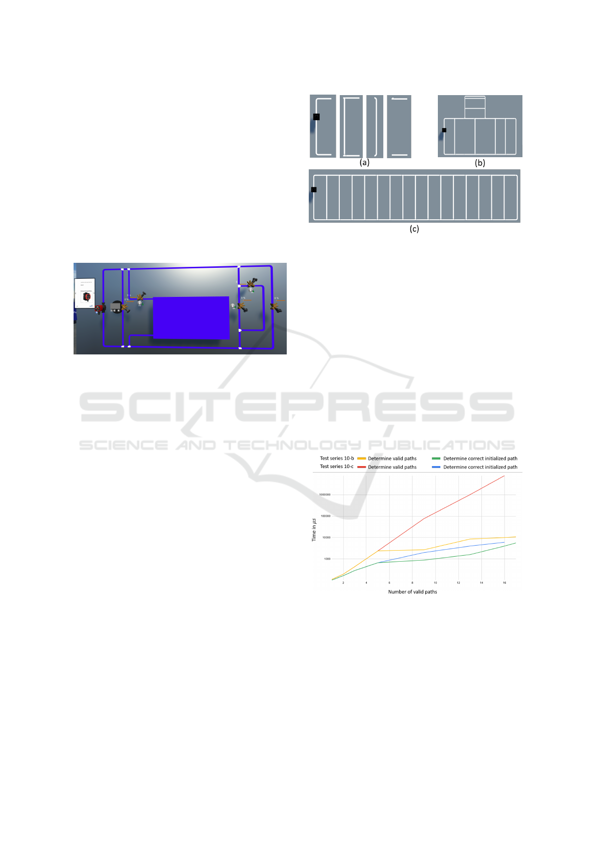
Figure 10-a depicts component blocks made up of
several system components that are used to build test
systems. Figures 10-b and 10-c show examples of test
systems developed for the evaluation.
The method for identifying network structure was
run 100 times for each test system. The time it took to
complete each loop’s various steps was measured and
documented. The mean value of the time measured
Figure 10: Creating evaluation tests.
for each step is used in the evaluation.
The analysis reveals a linear relationship between
the time required to identify connected elements
(sec. 3.2.1) and the total number of connectors, which
is a combined factor of the number of components
with 2 connectors and number of distributors.
The time required to determine the valid medium
transport paths (sec. 3.2.2) and the correct initialised
medium transport direction (sec. 3.2.3) is affected by
a variety of factors. We build many versions for each
of the systems in fig. 10-b and fig. 10-c by adding or
removing a number of middle-blocks (the second and
fourth blocks from the left in fig. 10-a). The time re-
quired for each of the two steps mentioned above is
shown in fig 11, which varies depending on the num-
ber of valid paths for the two test series.
Figure 11: Time measured for the test series.
The variations of both test series with the identical
structure and components are shown in the left part of
the diagram where the lines overlap. For variations
with similar number of valid paths and different num-
ber of components, it is demonstrated that the time
necessary for the test series 10-b is significantly less
than that required for the test series 10-c, particularly
for the determination of the valid path.
In general, the workflow duration is related to the
SIMULTECH 2023 - 13th International Conference on Simulation and Modeling Methodologies, Technologies and Applications
462

number of components, especially the number of dis-
tributors that define new branches in the system, as
well as the length of the longest feasible valid path.
The application of this approach allows a time and
effort reduction in configuring learning units in VR-
Lab4BES.
5 CONCLUSION
As a groundwork for BES simulation, this paper in-
troduced a workflow for automatically identifying the
network structure of medium transport systems as part
of BES models. The approach includes a suitable
object model with model elements required to de-
scribe the network structure and medium flow direc-
tion. The workflow is divided into three steps: (i)
identifying connected components, (ii) determining
valid medium transport paths, and (iii) determining
the correct initialised medium transport direction.
For validation, this approach was deployed as a
functional extension of the VR educational environ-
ment VRLab4BES and evaluated with multiple test
heating systems varying in device count and network
complexity. The tests show a positive outcome and a
significant reduction in effort in developing new vir-
tual reality learning units based on BES simulation.
This approach allows learners to freely create
and modify BES systems and apply simulation to
each component, rather than dealing with the time-
consuming and error-prone manual definition of
medium transport direction. For these use cases, re-
search into suitable interacting mechanisms in vir-
tual reality to ensure user-friendliness (e.g. 3D-grid
for auto-snap component placement) and the balance
between immersiveness and handiness of component
placement mechanism during complex system defini-
tion is required. Furthermore, due to the scope of this
paper, additional details about the hydraulic and ther-
mic simulation of a heating system in VR will be dis-
cussed in a subsequent publication.
The procedure of determining medium transport
direction based on the shortest distance to the network
starting point presented in this paper can be used to
other systems using other medium such as air, refrig-
erant, or electrical energie. Specific implementation
and considerations will be required depending on the
chosen trade.
REFERENCES
Behmadi, S., Asadi, F., Okhovati, M., and Sarabi, R.
(2022). Virtual reality-based medical education versus
lecture-based method in teaching start triage lessons
in emergency medical students: Virtual reality in med-
ical education. Journal of Advances in Medical Edu-
cation and Professionalism, 10(1), page 48.
Hall, F. and Greeno, R. (2017). Building services handbook.
Routledge, 9 edition.
Kaplan, A. D., Cruit, J., Endsley, M., Beers, S. M., Sawyer,
B. D., and Hancock, P. A. (2021). The effects of vir-
tual reality, augmented reality, and mixed reality as
training enhancement methods: A meta-analysis. Hu-
man factors, 63(4), pages 706–726.
Kapp, F., Matthes, N., Kruse, L., Niebeling, M., and
Spangenberger, P. (2022). Fehlerdiagnose mit virtual
reality trainieren–entwicklung und erprobung einer
virtuellen offshore-windenergieanlage. Zeitschrift f
¨
ur
Arbeitswissenschaft, pages 1–10.
Lau, K. and Lee, P. (2021). Using virtual reality for pro-
fessional training practices: exploring the factors of
applying stereoscopic 3d technologies in knowledge
transfer. Virtual Reality, 25(4), pages 985–998.
Lydon, G., Caranovic, S., Hischier, I., and Schlueter, A.
(2019). Coupled simulation of thermally active build-
ing systems to support a digital twin. Energy and
Buildings 202 (2019).
Mai, L. T. and Werdin, H. (2022). Vrlab4bes-a virtual real-
ity implementation approach of building service sim-
ulation for educational purposes. 2022 8th Interna-
tional Conference on Virtual Reality (ICVR), pages
82–89.
Milgram, P. and Kishino, F. (1994). A taxonomy of mixed
reality visual displays. IEICE TRANSACTIONS on In-
formation and Systems, 77(12), pages 1321–1329.
Milyutina, M. A. (2018). Introduction of building infor-
mation modeling (bim) technologies in construction.
Journal of Physics: Conference Series (Vol. 1015, No.
4, p. 042038). IOP Publishing.
Rad, R., Sadrabad, A., Nouraei, R., Khatony, A., Bashiri,
H., Bozorgomid, A., and Rezaeian, S. (2022). Com-
parative study of virtual and face-to-face training
methods on the quality of healthcare services provided
by kermanshah pre-hospital emergency staff (ems):
randomized educational intervention trial. Compar-
ative study of virtual and face-to-face training meth-
ods on the quality of healthcare services provided
by Kermanshah pre-hospital emergency staff (EMS):
randomized educational Intervention trial., pages 1–
7.
Tan, Y., Xu, W., Li, S., and Chen, K. (2022). Augmented
and virtual reality (ar/vr) for education and training in
the aec industry: A systematic review of research and
applications. Buildings 12, no. 10, page 1529.
Network Structure Identification for Medium Transport in a Virtual Reality Environment
463
