
Finite Element Simulation on the Tensile Property of Steel Cord at
Different Lay Lengths Under Axial Loading
Shanling Han
1
, Lingkang Kong
1
, Yanmeng Chi
1
, Long Chen
2
and Yong Li
1*
1
College of Mechanical and Electronic Engineering, Shandong University of Science and Technology,
Qingdao, Shandong, China
2
College of Materials Science and Engineering, Shandong University of Science and Technology,
Qingdao, Shandong, China
Keywords: Steel Cord, Lay Length, Tensile Property, Finite Element Analysis, Axial Loading.
Abstract: Steel cord is the primary load-bearing component of a tire, and as the tire environment becomes more
complicated and variable, greater tensile property demands are placed on the cord. There are several factors
that affect the tensile property of steel cord, with lay length being an important factor that is closely related to
the durability and quality of steel cord. Therefore, this paper takes 3×0.20+6×0.35HT steel cord as the
research object, establishes the parametric model with varying lay lengths, and employs the finite element
method to examine the effect of varying lay lengths on the tensile property. The results indicate that the
breaking strain of steel cord is lowest at the standard lay length. Furthermore, the breaking strain of steel cord
increases regardless of whether the lay length of the inner and outer monofilaments increases or decreases.
This study provides a basis and reference for the optimal design and manufacture of steel cord.
1 INTRODUCTION
Steel cord is widely used in rubber products (Zhang,
2019) such as tires and transportation belts because of
its high tensile strength, malleability, and stability
(Prawoto, 2012). The load-bearing capacity and
service life of steel cord are crucial to the safe
operation of rubber products. As the primary skeleton
material of rubber products, steel cord is subjected to
loads such as tension (Gurevich, 2022) and impact (Li,
2021), and its load-bearing strength and safe
operation are crucial to the service life (Kruzel, 2019).
During use, the steel cord will be abrasive and loose
between the monofilaments; as a result, the failure of
the steel cord due to stretching has become a major
concern among engineering designers and end-users.
To improve the safety factor of steel cord, the lay
length must be investigated. Nonetheless, in the
development of steel cord, the steel cord must be
repeatedly tested to determine its optimal parameters,
which is poorly oriented, time-consuming, and
wasteful of resources. For analyzing the stress-strain
analysis of complex metal structural products, finite
element analysis is more intuitive, highly accurate,
and widely used in the industry (Korunović, 2019).
Numerous scholars have conducted extensive
research on this topic, concentrating primarily on the
axial tensile property of steel cord.
Stanova (Stanova, 2011; Stanova, 2011)
developed mathematical geometric models of single
and double-layered wire ropes with specified initial
parameters, discussed the application of the derived
mathematical models, and carried out numerical
simulations of the established finite element models
for multilateral strands subjected to tension tests.
Chen (Chen,2021) and Abdullah (Abdullah, 2016)
have proposed techniques for modeling that are more
refined. Extensive research has been conducted on the
stress distribution law of the wire during tensioning
of the locking coil wire rope, as well as the behavior
of the prestressed strand after stress and fracture.
Fedorko (Fedorko, 2014) proposed a criterion for the
failure of locking coil wire ropes. And proposed an
accurate computational three-dimensional solid
modeling method for two-layer triangular wire
strands for finite element analysis, and used the three-
dimensional computational model for finite element
analysis of two-layer triangular steel strands
subjected to tensile loads. Ma (Ma, 2022) simulated
the multi-pass tensile process of wire with and
without eccentric inclusion under different back
tensions using the finite element method. All previous
finite element analyses made use of steel cord with a
standard lay length, ignoring the effect of lay length
64
Han, S., Kong, L., Chi, Y., Chen, L. and Li, Y.
Finite Element Simulation on The Tensile Property of Steel Cord at Different Lay Lengths Under Axial Loading.
DOI: 10.5220/0012149500003562
In Proceedings of the 1st International Conference on Data Processing, Control and Simulation (ICDPCS 2023), pages 64-71
ISBN: 978-989-758-675-0
Copyright
c
2023 by SCITEPRESS – Science and Technology Publications, Lda. Under CC license (CC BY-NC-ND 4.0)

on the tensile property of the steel cord. In general,
the breaking strain decreases as the lay length
increases. 3 × 4 × 0.22HE compared with 3 + 9 ×
0.22HE, the former lay length (3.15S/6.3S) than the
latter lay length (6.3S/12.5S) is twice as small,
although the diameter of the two monofilament and
the number of filaments is the same, but the former
break strain of up to 5-10%, the latter only about 2%;
from the physical test data, the former break tension
of 912 N, the latter is 830 N. the strength twist loss of
high elongation cord is often above 20%. Therefore,
the influence of lay length on tensile property needs
to be further explored.
This paper first will obtain the tensile curve of
3×0.20+6×0.35HT using a tensile machine, then will
establish the parametric model of 3×0.20+6×0.35HT
and verify the accuracy and feasibility of the
simulation by comparing it with experimental data.
Finally, models with an inner lay length of 10 mm and
an outer lay length of 12.5, 14.0, 16.0, 18.0, 20.0, and
22.4 mm will be created, as well as models with an
inner lay length of 8.0, 9.0, 10.0, 11.2, 12.5 and 14.0
mm and an outer lay length of 18 mm. To examine the
effect of different lay lengths on tensile property.
2 FINITE ELEMENT ANALYSIS
OF TENSILE STEEL CORD
2.1 The Establishment of the Finite
Element Model
As an example, this study models a steel cord of type
3×0.20+6×0.35HT (Fig. 1a). The cross-sectional
view of this cord is shown in Fig. 1(b). This type of
cord is one of the simpler cord structures, consisting
of two layers of steel monofilaments twisted inside
and outside, with each layer evenly distributed along
the circumference and both layers in a single spiral
structure. The parameters such as diameter, lay length,
diameter, distance from inner and outer cord to the
center are listed in Table 1.
Figure 1: Steel cord: (a) appearance, (b) cross-sectional view.
Table 1: 3×0.20+6×0.35HT steel cord parameters.
Material properties Value
Length (mm) 15
Diameter (mm) 1.13
Inner cord lay length (mm) 10
Outer cord lay length (mm) 18
Inner cord diameter (mm) 0.2
Outer cord diameter (mm) 0.35
The distance from the inner cord to the center (mm) 0.118
The distance from the outer cord to the center (mm) 0.394
Breaking stress (MPa) 2918.68
Breaking strain (%) 0.0208
Finite Element Simulation on The Tensile Property of Steel Cord at Different Lay Lengths Under Axial Loading
65

Figure 2: Specific procedure: (a) generates center helices, (b) sweep, (c) closed, (d) circular array.
Figure 3: 3×0.20+6×0.35HT steel cord: (a) force- displacement curve, (b) stress-strain curve.
The standard lay lengths are 2.5, 2.8, 3.1, 3.5, 4.0,
4.5, 5.0, 5.6, 6.3, 7.1, 8.0, 9.0, 10.0, 11.2, 12.5, 14.0,
16.0, 18.0, 20.0, 22.4, 25.0, etc. 3×0.20+6×0.35HT is
used as the research object, and models with inner lay
length of 10 mm and an outer lay length of 12.5, 14.0,
16.0, 18.0, 20.0, and 22.4 mm are established, as well
as models with inner lay lengths of 8.0, 9.0, 10.0, 11.2,
12.5, and 14.0 mm and outer lay lengths of 18 mm.
These models are used to examine the effect of
different lay lengths on the stress distribution and
strain.
Based on the above parameters, parametric
modeling of the steel cord can be achieved by the
spiral sweep and circular array functions. Firstly, the
center line of the steel cord and the cross section of
two kinds of monofilaments are established (Fig. 2a),
then the helices are generated, and the curve
smoothing is used to adjust the curvature
inconsistency of the intersection point of the helix,
then the solid model of the monofilaments is
completed with the sweep (Fig. 2b) and closed
surface (Fig. 2c) commands, and finally the complete
steel cord is completed with the circular array (Fig.
2d) command.
2.2 Material Properties
Analysis of steel cord using finite elements is a
nonlinear problem requiring the definition of material
parameters, the construction of the mesh system, the
configuration of the solver, the construction of
connection relations, the establishment of boundary
conditions, and post-processing. Based on the explicit
dynamic solver, a simulation study of the tensile steel
cord is carried out
The steel cord is a high-carbon steel, and the
steel cord is an elastoplastic material. In material
systems, elastoplastic materials are usually defined by
the following parameters: ductile damage, density,
elasticity, and plasticity. To simulate a real cord
stretching experiment, the steel cord is pulled off by
the traditional German Zwick electronic universal
testing machine with a tensile speed of 100 mm/min.
The stress-strain curve is calculated from the force-
displacement curve of the cord stretched in the press,
and the curve is measured and plotted using
specialized tools. these parameters are calculated
from the stress-strain curve (Fig. 3a) obtained by
stretching 3×0.20+6×0.35HT cord in a press, and the
stress-strain curve is shown in Fig. 3(b).
The density of steel cord is
93
7.95 10 /tmm
−
×
;
Young's modulus of elastic property is
11 2
1.81 10 /Nmm×
, Poisson's ratio is 0.3; breaking
strain, stress triaxiality, strain ratio and damage
evolution of ductile damage are 0.207, 0.333, 0.001
and 0.02 respectively. The experimental data of the
press are given in terms of nominal stress and nominal
strain and considering the effect of material necking
on the data. The real stress and real strain are used to
define the plasticity data. Therefore, the
transformation from nominal stress/strain to real
stress/strain has to be realized, and the transformed
stress-strain curve is shown in Fig. 3.
ICDPCS 2023 - The International Conference on Data Processing, Control and Simulation
66

Figure 4: Key steps of finite element analysis: (a) mesh generation, (b) coupling.
Figure 5: Boundary conditions at both ends of the steel cord.
2.3 Mesh Generation and Contact
Condition
Because each monofilament within the steel cord has
central symmetry, the mesh division of each
monofilament also has central symmetry. In
consideration of the geometric characteristics of the
monofilament and contact, etc., and to eliminate the
influence of the mesh type on the analysis of
experimental results, the uniform use of C3D4 mesh
type, and to consider the accuracy of simulation
results and calculation time. Meshes with dimensions
of 0.05 mm are used for the finite element analysis.
The meshed model can be seen in Fig. 4(a).
Considering the contact between the
monofilaments of the steel cord during the tensile
process, the surface-to-surface contact type is defined.
This method yields more accurate results, but it is
time-consuming. Therefore, instead of setting up
contact pairs for two individual monofilaments, a
global setup is used with a contact behavior of hard
contact normal to the steel cord surface and a friction
coefficient of 0.19 between brasses of the steel cord
surface material in the radial direction.
To accurately simulate the tensile experiment on
both ends of the steel cord testing machine's
stretching state, the simulation incorporated the
following boundary conditions: one end of the steel
cord degrees of freedom by way of motion coupling
constraint to the reference point RP-1 (Fig. 4b). the
reference point RP-1 coupling steel cord end surface
into a fixed relationship, the reference point has six
degrees of freedom, specifically three translational
degrees of freedom, three rotational degrees of
freedom. The load is only applied in the axial
direction to the monofilament, and the remaining
degrees of freedom are null.
2.4 Boundary Conditions
The boundary conditions of the steel cord are imposed
as shown in Fig. 5, where the reference point RP-1
moves uniformly along the axial direction at 0.6 mm
in 0.15 s under axial tension, and the other end of the
steel cord is fixedly restrained.
Finite Element Simulation on The Tensile Property of Steel Cord at Different Lay Lengths Under Axial Loading
67
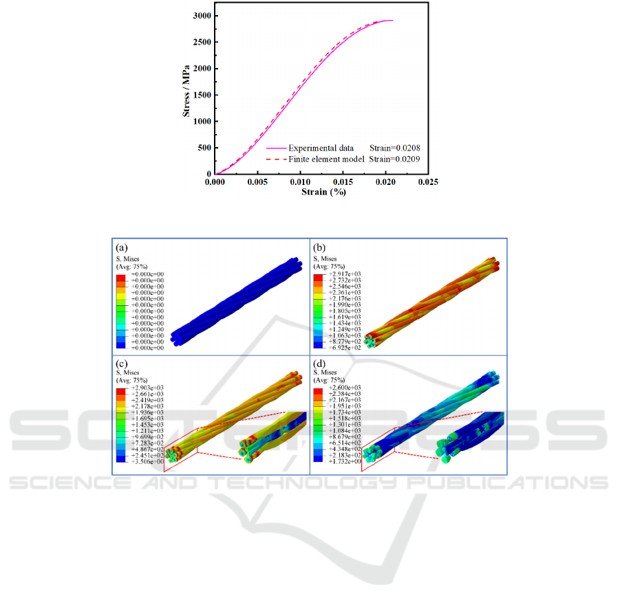
Figure 6: Experimental data and finite element model of tensile stress-strain curves.
Figure 7: Tensile process of steel cord: (a) initial state, (b) maximum stress reached, (c) inner layer monofilament breakage,
(d) outer layer monofilament breakage.
3 RESULTS AND DISCUSSION
Two types of results to study the overall mechanical
property of the tensile action steel cord are analyzed
in this article: stress distribution and strain.
(1) First, the tensile simulation is conducted for
the finite element model with the standard inner lay
length of 10 mm and outer lay length of 18 mm, and
the stress-strain curve obtained is shown in Fig. 6.
The breaking strain is 2.09%, and the deviation from
the tensile test is only 0.625%; the tensile property of
the steel cord obtained from the simulation result are
consistent with the actual measured value, which
provides a comparison of the tensile property of the
steel cord. This provides a basis for the tensile
comparison of finite element models with different
lay lengths, and the finite element analysis process is
also authentic and reliable.
(2) The finite element model tensile process
and the stresses in its cross section are shown in Fig.
7 and Fig. 8. The stresses within the steel cord cross
section exhibit a centrally symmetrical distribution
and a decreasing trend outward. Compared to the
outer layer, the inner layer of the cord is subjected to
a greater stress, which means that the inner
monofilament is subjected to a larger load. As a result,
inner monofilament breaks first (Fig. 7c), followed by
the outer monofilament (Fig. 7d). Due to the different
lay lengths of the steel cord, the cross section of the
steel cord is roughly divided into three cases from a
radial perspective: first (Fig. 8b1), there is a small gap
between the monofilaments of the steel cord,
relatively independent, there is no extrusion
phenomenon, the steel cord is only subject to axial
tensile load, when the load distribution is relatively
uniform and no stress concentration phenomenon
arises. Second (Fig. 8b2), the inner three
monofilaments are extruded by the outer six
ICDPCS 2023 - The International Conference on Data Processing, Control and Simulation
68
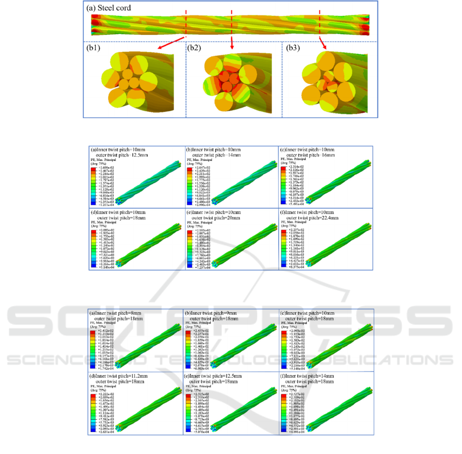
Figure 8: Stress distribution: (a) steel cord in the stretched state, (b) three typical cross-sections.
Figure 9: Steel cords with inner lay lengths of 10 mm and outer lay lengths of (a) 12.5, (b) 14.0, (c) 16.0, (d) 18.0, (e) 20.0,
and (f) 22.4 mm.
Figure 10: Steel cords with inner lay lengths of (a) 8.0, (b) 9.0, (c) 10.0, (d) 11.2, (e) 12.5, and (f) 14.0 mm and outer lay
lengths of 18 mm.
monofilaments, and the inner three monofilaments are
extruded from one another. When the inner
monofilaments are subjected to axial tensile and
extrusion, the stress is the highest; therefore, it is also
easy to break in this section. Third (Fig. 8b3), the
inner three monofilaments don’t receive the extrusion
of the outer layer of steel cord; only the inner three
monofilaments extrude each other. At this group, the
steel cord received tensile and extrusion force, and the
stress is higher.
(3) The breaking strains at 2918 MPa for models
with inner lay lengths of 10 mm and outer lay lengths
of 12.5, 14.0, 16.0, 18.0, 20.0, and 22.4 mm and for
models with inner lay lengths of 8.0, 9.0, 10.0, 11.2,
12.5, and 14.0 mm and outer lay lengths of 18 mm are
depicted in Fig. 9 and Fig. 10. When the inner layer
lay length is 10 mm and the outer layer lay length is
12.5 mm, the maximum breaking strain is 2.69%,
with a deviation of 28.71% from the breaking strain
of steel cord at the standard lay length. The breaking
strain tends to decrease with increasing lay length for
both the inner and outer layers. The minimum
breaking strain for 3×0.20+6×0.35HT with standard
lay lengths of 10 mm for the inner layer and 18 mm
for the outer layer is 2.09%, while the breaking strain
increases with increasing lay length when the inner
layer lay length is greater than 10 mm and the outer
layer lay length is greater than 18 mm. As shown in
Finite Element Simulation on The Tensile Property of Steel Cord at Different Lay Lengths Under Axial Loading
69

Figure 11: Strain-lay length curves: (a)steel cord with 10 mm inner lay length, (b) steel cord with 18 mm outer
lay length.
Fig. 11, it can be observed that the breaking strain of
the steel cord increase regardless of whether the lay
length is increased or decreased in comparison to the
standard lay length, which is consistent with the
results of actual steel cord manufacture.
4 CONCLUSION
Steel cord tensile property are influenced by several
parameters, including lay length. A parametric model
of 3×0.20+6×0.35HT steel cord is developed and
compared to the stress-strain curve obtained from a
tensile test. The deviation of the breaking strain from
the tensile test is only 0.625%, which proves the
simulation's accuracy and prepares for the upcoming
experiments.
In this paper, the steel cord loading cross-section
is categorized based on the difference in stress
distribution: first, each monofilament of the inner and
outer layers is extrusion-free and only experiences
tensile stress. Second, the inner monofilaments
extrude each other and receive the extruding effect of
the six outer monofilaments simultaneously, at which
group the inner monofilaments carry the most stress
and will break first, followed by the outer
monofilaments. Third, just the inner monofilaments
extrude each other while the outer monofilaments do
not exert any pressure. This research also compares
the breaking strain of steel cords with various lay
lengths and standard lay lengths. When the lay length
is standard, the steel cord's breaking strain is minimal.
Whether the lay length of the inner or outer
monofilaments increases or decreases, the steel cord
fracture strain increases. Also consistent with actual
steel cord manufacturing results.
ACKNOWLEDGMENT
This work was supported by National Nature Science
Foundation of Shandong Province of China (Grant
No. ZR2022ME118).
CONFLICTS OF INTEREST
The authors declare that they have no known
competing financial interests or personal
relationships that could have appeared to influence
the work reported in this paper.
REFERENCES
Zhang P, Duan M, Ma J, zhang Y. (2019). A precise
mathematical model for geometric modeling of wire
rope strands structure. Applied Mathematical
Modelling. 76:151-71.
Prawoto Y, Mazlan RB. (2012). Wire ropes: Computational,
mechanical, and metallurgical properties under tension
loading. Computational Materials Science. 56:174-8.
Gurevich L, Danenko V, Bogdanov A, Kulevich V. (2022).
Analysis of the stress-strain state of steel closed ropes
under tension and torsion. International Journal of
Advanced Manufacturing Technology. 118:15-22.
Li Y, Sun X, Song J, Zhang S, Han S. (2021). Topological
structure and experimental investigation of a novel
whole tire bead. Materials & Design. 203:109592.
Kruzel R, Ulewicz M. (2019). The fatigue strength of
bidirectionally bent steel cord used in tyres.
Engineering Failure Analysis. 105:176-81.
Korunović N, Fragassa C, Marinković D, Vitković N,
Trajanović M. (2019). Performance evaluation of cord
material models applied to structural analysis of tires.
Composite Structures. 224:111006.
Stanova E, Fedorko G, Fabian M, Kmet S. (2011).
Computer modelling of wire strands and ropes Part I:
Theory and computer implementation. Advances in
ICDPCS 2023 - The International Conference on Data Processing, Control and Simulation
70

Engineering Software. 42:305-15.
Stanova E, Fedorko G, Fabian M, Kmet S. (2011).
Computer modelling of wire strands and ropes part II:
Finite element-based applications. Advances in
Engineering Software. 42:322-31.
Chen Z, Guo L, Liu H, Chen H. (2021). Finite element
study of behaviour and interface force conditions of
locked coil wire rope under axial loading.
Construction and Building Materials. 272:121961.
Abdullah ABM, Rice JA, Hamilton HR, Consolazio GR.
(2016). An investigation on stressing and breakage
response of a prestressing strand using an efficient
finite element model. Engineering Structures.
123:213-24.
Fedorko G, Stanova E, Molnar V, Husakova N, Kmet S.
(2014). Computer modelling and finite element
analysis of spiral triangular strands. Advances in
Engineering Software. 73:11-21.
Ma A, Zhang Y, Dong L, Yan H, Fang F, Li Z. (2022).
Damage and fracture analyses of wire with off-center
inclusion on multi-pass drawing under different back
tensions. Engineering Failure Analysis. 139:106512.
Finite Element Simulation on The Tensile Property of Steel Cord at Different Lay Lengths Under Axial Loading
71
