
Sliding Mode Formation Control for Multiple Hypersonic Glide
Vehicles
Dongdong Yao
1,*
,
Yandong Hu
2
, Dawei Liu
3
and Qunli Xia
1
1
School of Aerospace, Beijing Institute of Technology, Beijing, China
2
Zhengzhou University of Aeronautics, Zhengzhou, China
3
China Research Development Academy of Machinery, Beijing, China
Keywords: Hypersonic Glide Vehicle, Formation Controller, Sliding Mode Control, State Observer, Sign of Bank
Angle.
Abstract: Aiming at the formation flying problem multiple hypersonic gliding vehicles, a formation controller design
method based on sliding mode control theory is proposed. Firstly, according to the vehicle motion model
and the multi-body "leader-follower" motion model, the trajectory of the leader and the state equation of the
follower are obtained. Based on the sliding mode control theory, a formation controller is designed to
maintain the relative position between the follower and the leader in terms of altitude and speed. The
extended state observer is designed to eliminate formation modeling errors and flight process errors. On this
basis, the control variable is transformed from acceleration to attack angle and bank angle. According to the
lateral relative position and heading angle direction, the sign change logic of the bank angle is designed to
ensure that the lateral relative position can meet the formation distance requirements. Simulation results
show that the proposed control method can achieve the desired multi-hypersonic vehicle formation flying.
1 INTRODUCTION
Hypersonic glide vehicle has become the focus of
research in many countries because of its high speed,
high precision and long range (ZHAO, 2014).
Facing the complex battlefield environment and
diverse combat tasks, with the improvement of
vehicle performance, multiple hypersonic vehicles
can improve the communication and detection
ability during glide by flying in formation, and is
conducive to the realization of coordinated attack on
the target during the terminal guidance period.
Therefore, it is important to study the formation
control method of multiple hypersonic glide vehicles
(GUO, 2022; SHUI, 2020).
Hypersonic glide vehicle has the characteristics
of strong nonlinear model, severe flight environment,
wide flight space and strict flight constraints. Its
only control force is aerodynamic, so accurate
formation control of hypersonic vehicles is very
complicated and difficult to achieve (An, 2022).
Therefore, when considering the formation space
configuration, it is not necessary to keep an accurate
space configuration of multiple aircraft, but only
need to maintain the relative position in a certain
space to form an "inaccurate formation", so as to
ensure that the aircrafts can realize the
communication, detection, middle and terminal
guidance transition and other functions during the
flight.
The cooperative formation control of
hypersonic glide vehicles can be based on three
methods (WANG, 2019). The first is based on the
cooperative trajectory planning of multiple aircraft,
and obtains the trajectory of each aircraft by setting
various constraints of the aircraft (CHU, 2017; YU,
2020; GAO, 2022). The second is based on the
formation controller, which is usually based on the
"leader-follower" formation model. The formation
controller is designed to keep the following aircraft
(hereinafter referred to as "follower") in relative
space position (ZHANG, 2021; ZHANG, 2021; WEI,
2022). The third is based on the distributed
consensus algorithm, and according to the
communication topology, the consistency control
law is designed to realize the formation flight of
multiple aircraft (Wei, 2021; Zhao, 2017; LI, 2020).
Among them, the first method can fully consider the
flight capability of the aircraft, but it usually
establishes the cooperative control law through the
flight time, and the cooperative trajectory planning
method through the formation space configuration
Yao, D., Hu, Y., Liu, D. and Xia, Q.
Sliding Mode Formation Control for Multiple Hypersonic Glide Vehicles.
DOI: 10.5220/0012150900003562
In Proceedings of the 1st International Conference on Data Processing, Control and Simulation (ICDPCS 2023), pages 133-140
ISBN: 978-989-758-675-0
Copyright
c
2023 by SCITEPRESS – Science and Technology Publications, Lda. Under CC license (CC BY-NC-ND 4.0)
133

still needs further research. The second method is
easier and more efficient to realize formation and
maintenance, but the formation members are highly
dependent on the information of the leading aircraft
(hereinafter referred to as "leader"), which is easy to
be interfered with. The third method can also
quickly form and maintain formation, and is less
affected by a single aircraft, but it puts forward
higher requirements on the ability of aircraft to
communicate and process information. In addition,
due to the lack of thrust and the under-saturation and
strong coupling characteristics of the gliding vehicle
(WANG, 2018), the three-axis’s acceleration cannot
be projected directly into the aerodynamic force,
which makes it difficult to deal with the control
variable obtained by the latter two methods above.
Based on the above research, this paper takes
the hypersonic glide vehicle as the research object
and designs a sliding mode formation controller
based on the "leader-follower" formation model to
ensure that multiple vehicles maintain relative
configuration within a certain range during flight.
Firstly, according to the aircraft motion model and
the "leader-follower" formation model, the leader
trajectory is given and the follower state equation is
obtained. Then, according to the sliding mode
control theory, a formation controller with extended
state observer (ESO) is designed to satisfy the
formation requirements of multiple aircraft.
Considering that attack angle and bank angle are the
actual control variables, the calculation method of
the attack angle and the sign change method of the
bank angle are designed so that the horizontal
direction of aircraft can meet the relative distance
constraints. Simulation results show the
effectiveness of the method.
2 HYPERSONIC VEHICLE
MODEL DESCRIPTION
The motion model of the aircraft refers to the
literature (Lu, 2014), and there is a three-degree-of-
freedom motion equation in the half-velocity
coordinate system, as shown in fig.1.
where, r is the distance between the vehicle and
the center of the earth, λ and φ denote latitude and
longitude respectively, v is the velocity of the
vehicle, θ and ψ denote flight path angle and
azimuth angle respectively, m is for mass, σ is the
bank angle, g is the acceleration of gravity. D and L
represent drag and lift, whose calculation formula is
shown as fig. 2.
1
rvsin
vcos sin
rcos
vcos
o
cos
r
vDgsin
m
L cos g cos
r
vcos
mv v
Lsin v
mv
tan c s s n
cos
i
r
θ
θψ
λ
φ
θψ
φ
θ
σθθ
θ
σ
φ
θ
ψ
ψ
θ
=
=
=
=− −
=−+
=−
−
(1)
Figure 1: Relative motion relation of the leader and
follower
.
L
D
L
qSC
DqSC
=
=
(2)
where, q is the dynamic pressure, S is the
aerodynamic reference area, C
L
and C
D
represent lift
coefficient and drag coefficient.
Considering the dynamic pressure, heat flux
density and overload constraints of the leader, there
is
max
max
max
qq
QQ
nn
≤
≤
<
(3)
where,
Q
is the heat flux density, n is the overload,
the subscript
max indicates the maximum value.
The formation model is established according to
the reference (Amer, 2020), as shown in fig.1.
x
y
z
o
f
x
f
y
f
z
l
x
l
y
l
z
f
o
l
o
l
r
f
r
r
ICDPCS 2023 - The International Conference on Data Processing, Control and Simulation
134

Taking the leader trajectory coordinate system as the reference system, the relative motion equations for the
leader and follower are give:
()
()
()
cos cos cos sin sin cos
sin cos cos cos sin sin
cos sin cos sin
cos
lf lff lffl lll
ll lff lffl ll
f l f f ll ll
fx
y
f
f
z
f
ff
x
vvyzv
yvvxz
zvxy
va
a
v
a
v
θθ ψψ θθ θ θψ
θθ ψψ θθ θ θψ
θψψ θψ θψ
θ
ψ
θ
=−++−−
=− − + − +
=−+−
=
=
=−
(4)
()
()
()
cos
cos
sin
cos
lfflffl l x
llffffllly
lffl ll z
fx
y
f
f
z
f
ff
xvvyzd
yvvxzd
zvxyd
va
a
v
a
v
ψψ θθ θ ψ
θψψ θ θθψ
ψψ ψ θψ
θ
ψ
θ
=−++−+
=− − + − + +
=−+−+
=
=
=−
(5)
where, the subscript
l indicates the states of the
leader, the subscript f indicates the states of
followers, x, y and z represent three-axis’s relative
position of followers,
a
x
, a
y
and a
z
are three-axis’s
acceleration.
For the formation model shown in equation (4),
since the relative position equation of the follower is
established in the leader trajectory coordinate system,
and the earth curvature is not taken into
consideration, the reference inertial coordinate
system of the leader and the followers is the ground
coordinate system (NUE coordinate system) during
the coordinate system transformation. However,
when the curvature of the earth is considered, the
ground coordinate system of the two will no longer
coincide. At this time, the relative position obtained
ccording to equation (3) will result in modeling
errors caused by curvature. When two vehicles are
10km apart, the error value is about 8m, when the
they are 100km apart, the error value is about 0.8km.
It can be seen that if the relative position of the
leader and follower is less than 100km, the relative
error is less than 1%, but as the distance increases,
the absolute error also increases, and the error needs
to be properly processed according to the
requirements.
In the simulation of most literatures (Brian, 2021;
Wang, 2018; Wang, 2017), the absolute value of
flight path angle is no more than 10°, so it can be
simplified as follows: sin
θ = θ, cosθ = 1. Meanwhile,
considering the modeling and process errors d
x
, d
y
and d
z
, equation (3) can be simplified as equation (5)
3 DESIGN OF SLIDING MODE
FORMATION CONTROLLER
According to reference (LI, 2021), keeping a specific
space configuration during the flight of multiple
hypersonic vehicles can improve the detection ability
of the group. In this paper, the formation space
configuration of multi-vehicle is "one-line". Due to
the constraint of aircraft control ability, the distance
between two aircraft in Z-axis direction should be
given within a certain range. The minimum distance
R
min
is given according to the safe distance between
the two aircraft, and the maximum distance R
max
is
given according to the communication ability.
3.1 Sliding Mode Controller Design
According to equation (5), the state equation of
Sliding Mode Formation Control for Multiple Hypersonic Glide Vehicles
135

aircraft can be written as equation (6). Since the
distance in the
z direction is controlled by the bank
angle symbol, it only needs to design the sliding
mode surface that controls the state in the
x and y
directions.
112
2
X
AX BX F D
XGU
=+++
=
(6)
[]
()
()
12
0
1
1
10
1
TT
T
fff xy
lf l
l
l
lfl
ll
f
ll
xy
XxyX v v Uaa
cos
AB
cos
vz
FG
z
Ddd
θ
ψψ θ
θ
θ
ψψθ
ψ
θ
θψ
== =
−
==
−
−−
−−
==
=
According to the design principle of sliding mode
control (Li, 2005), the function of sliding mode and
the approach law are taken
()
12
11 1
22 2
sgn >0, 0
d
d
sce e
ssksk
eX X
eX X
εε
=+
=− − >
=−
=−
(7)
where, X
1d
and X
2d
are the expected values of X
1
and
X
2
. For X
2d
. Using the backstepping method, X
2d
can
be expressed as
()
1
2111d
X
BkeAXFD
−
=−−−−
(8)
In order to track and keep the relative position of
the follower, according to equation (7), there is
()( )
()
12
11 1
22 2
11 2 2
sgn
d
d
dd
sce e
eX X
eX X
cX X X X s ks
ε
=+
=−
=−
−+ − =− −
(9)
The control law is obtained by taking equation (6)
into equation (8), show as in equation (10)
()
()
112
1
2
d
d
c X AX BX F D
UG
Xsgnsks
ε
−
−−−−+
=
++
(10)
The design of the sliding mode surface and the
reaching law above can ensure
0ss ≤
, that is,
Lyapunov function
2
2Vs/=
is positive definite
and its derivative is negative definite. The system
can stabilize on the sliding mode surface after
reaching it, that is, the error tends to zero.
3.2 Extended State Observer Design
According to reference (Li, 2005), an extended state
observer is designed to estimate the bounded
composite disturbance D.
First define the expanded state X
1e
, assuming
D
υ
=
, considering the first formula in equation (6),
the state equation can be written as
112 1
1
e
e
X
AX BX F X
X
υ
=+++
=
(11)
The ESO is used to estimate X
1
and X
1e
, and the
calculation formula is
()
1111
11 1 2 12 11 1
12 12 1
EZ X
Z
AX BX F Z E
ZfalE,,
β
βαδ
=−
=+++−
=−
(12)
where, E1 is the observation error of X
1
, Z
11
and Z
12
are the observation values of X
1
and X
1e
respectively.
β
11
>0 and
β
12
>0 are the observed gain of ESO,
α
>
0and
δ
>0 are the parameters to be designed.
The function fal(E
1
,
α
,
δ
) is defined as
()
()
111
1
1
11
EsgnE E
fal E , ,
E/ E
α
α
δ
αδ
δδ
−
>
=
≤
(13)
By designing a reasonable value of
β
11
,
β
12
and
α
1
,
it can be ensured that ESO can observe and
dynamically compensate X
1
and X
1e
well.
Substituting D with the observed variable Z
12
,
equation (10) can be rewritten as
()
()
112 12
1
2
d
d
c X AX BX F Z
UG
Xsgnsks
ε
−
−−−−+
=
++
(14)
Since the error is less than 1% of the expected
distance, the error is bounded and does not affect in
the stability of the controller.
3.3 Control Instruction Assignment
Design
The control instruction obtained Section 3.1 is
acceleration, U = [a
x
, a
y
]
T
. However, the actual
control variables of the aircraft are the attack angle
and the bank angle, so, it is also necessary to obtain
the relationship between acceleration and angle.
According to equation (1), (2) and (5), there is
ICDPCS 2023 - The International Conference on Data Processing, Control and Simulation
136

2
xD
yL
qS
av Cgsin
m
qS v cos
av Ccos gcos
mr
θ
θ
θσθ
==− −
== − +
(15)
where, (C
D
、C
L
) = f (α,Ma). It can be seen that the
control variables a
x
has a direct mapping relationship
with the attack angle, which can be obtained by
aerodynamic inverse interpolation. However, the
attack angle and the bank angle are coupled items, so
they cannot be solved directly by a
y
. It is necessary
to use the angle of attack and a
y
to solve the value of
the bank angle.
For the sign of the course angle, the classical
method adopts the course angle corridor to
determine the sign (Ma, 2017). First set the course
angle error threshold. When the course angle error
exceeds the preset error threshold, change the bank
angle sign to make the course angle return to the
corridor; when the course angle error does not
exceed the error corridor, keep the course angle sign
unchanged.
In this paper, based on the idea of the error
threshold, the sign change logic of the bank angle is
designed to ensure the follower can maintain the
relative position in the z-axis direction. At the same
time, the error threshold is designed according to the
relative position error in the z-axis direction and
cruse angle. Take R
1
and R
2
to satisfy R
min
< R
1
< R
2
<
R
max
. There is
()
()
()
()
1
12
2
min
fld
max
sgn R R R R
s
gn sgn R R R
sgn R R R R
σψψψ
−<
=− − − < <
−<
(16)
where,
d
ψ
represents the error threshold. This is to
ensure that when the aerodynamic force meets the
control requirements, the aircraft will stay away
when it is close and close when it is far away, so that
the relative position can be kept within the expected
distance range. In the relatively centered distance
range, try to keep the speed direction consistent with
the leader.
4 SIMULATION
The Common Aero Vehicle (CAV) is selected as the
simulation object, its aerodynamic model is (CHEN,
2014)
4
4
3.025 10
29.49510
0.232 2.94 0.295
0.024 2.38 0.406
v
L
v
D
Ce
Ce
α
α
−
−
−×
−×
=− + +
=+ +
(17)
The US 1976 atmospheric model is selected as the
atmospheric environment, the characteristic area of
the aircraft is S = 0.48378m
2
, and the mass of the
aircraft is m = 907kg. The maximum attack angle is
25°, and the maximum bank angle is ±90°.
The leader adopts a balanced gliding trajectory,
with
0
θ
=
, satisfying
()
2
1
0
cos
Lcos v
rr
θ
σ
+− =
(18)
The bank angle of the leader is always 0°, and the
gliding reaches a height of 30km. The heat flow,
dynamic pressure and overload constraints during
flight are: Q
max
= 2000Kw/m
2,
q
max
= 500kPa, n
max
=
15. R
min
=5km, R
1
=8km, R
2
=13km, R
max
=15km. The
initial states of the leader, follower 1 and follower 2
are shown in Table 1.
Table 1: The initial state of the leader and followers.
h/km
(λ
、φ)/°
v/m·s
-1
θ/° ψ/°
Leader 60
(0、0)
5000 0 0
follower1 65
(0.13、0.01)
5000 0 0.1
follower2 63
(-0.12、-0.01)
5000 0 0.1
The simulation results are as follows.
Sliding Mode Formation Control for Multiple Hypersonic Glide Vehicles
137
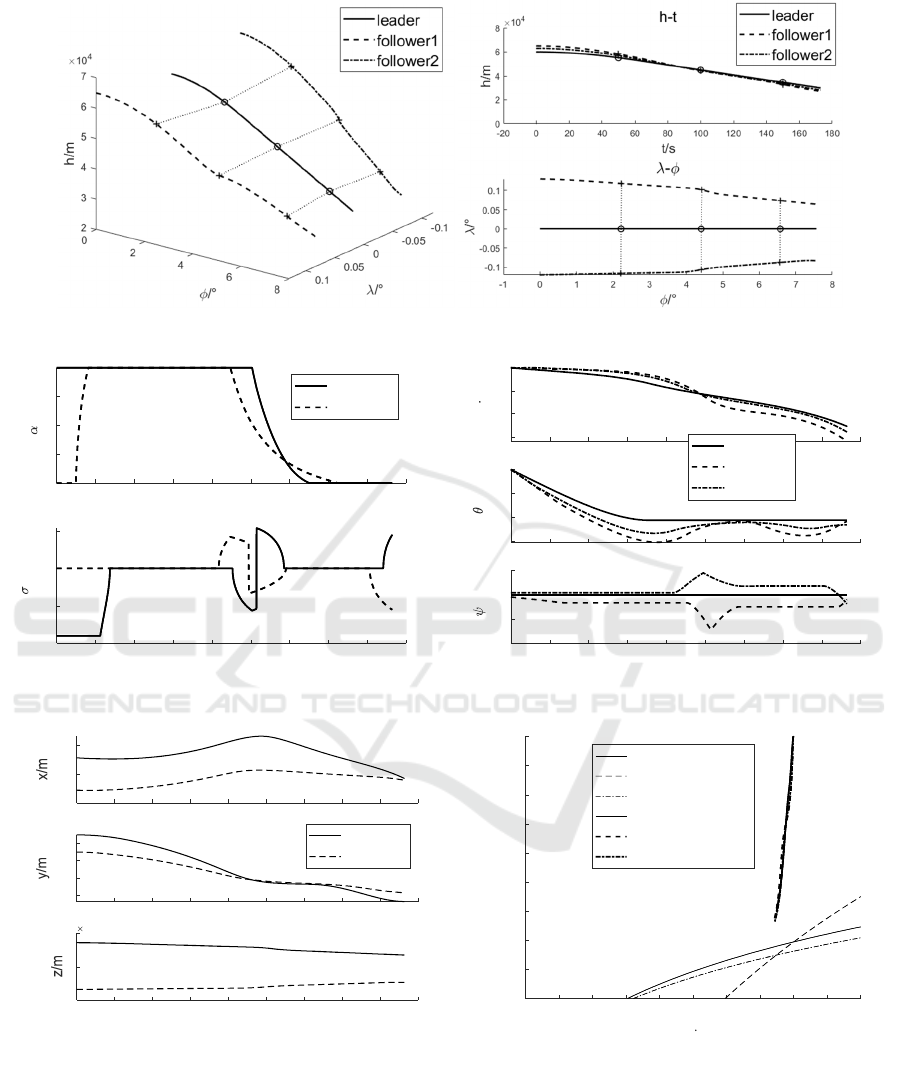
Figure 2: Trajectory of leader and followers. Figure 3: Longitudinal and lateral trajectory.
Figure 4: Curves of attack angle and bank angle. Figure 5: Curves of speed, flight path angle and course angle.
Figure 6: Followers position of x,y and z. Figure 7: H-V flight corridor.
It can be seen from Figure 2-Figure 7 that the
two followers can maintain the spatial configuration:
the initial errors in the x-axis direction are 1km and -
1km respectively, and with the adjustment during the
flight, the errors tend to 0 but are not stable at 0. This
is because the limitation of aircraft control capability
and the coupling of control variables. During the
flight, the error in the x direction of follower1 does
not exceed 2km, and that of follower2 does not
exceed 1km. Similarly, the initial altitudes of the two
followers are 63km and 65km, respectively, and the
altitude error (y-direction error) also approaches 0
during the flight, and the steady-state error is not
maintained at 0, but the error does not exceed 1.5km.
0 20 40 60 80 100 120 140 160 180
5
10
15
20
25
/°
follower1
follower2
0 20 40 60 80 100 120 140 160 180
t/s
-100
-50
0
50
/°
0 20 40 60 80 100 120 140 160 180
4700
4800
4900
5000
v/m s
-1
0 20 40 60 80 100 120 140 160 180
-0.06
-0.04
-0.02
0
/°
0 20 40 60 80 100 120 140 160 180
t/s
-0.04
-0.02
0
0.02
/°
leader
follower1
follower2
0 20 40 60 80 100 120 140 160 180
-2000
0
2000
0 20 40 60 80 100 120 140 160 180
-2000
0
2000
4000
follower1
follower2
0 20 40 60 80 100 120 140 160 180
t/s
-2
0
2
10
4
1000 1500 2000 2500 3000 3500 4000 4500 5000 5500 6000
v/m s
-1
15
20
25
30
35
40
45
50
55
60
h/km
dynamic pressure
heat flow
overload
leader
follower1
follower2
ICDPCS 2023 - The International Conference on Data Processing, Control and Simulation
138

Figure 8: Comparison of trajectories. Figure 9: Comparison of position.
In the z direction, the two followers approach
the leader after 100s and stabilize at about 8km. In
addition, the H-V curves of the leading aircraft are
all within the corridor constraints, satisfying the
flight process constraints.
Add 1% error to the relative position, and add
ESO to the controller at the same time. The observer
constants are respectively selected as
α
= 0.15,
δ
=
0.15
,
β
1
= 25,
β
2
= 50. Taking follower1 as the
research object, the trajectory simulation comparison
results are obtained.
It can be seen from Figure 8 and Figure 9 that
after increasing the position error and the observer,
the trajectory of follower1 will change. The
trajectories have little difference in the x and y
directions, but as the flight time increases, the
relative position in the z direction gradually develops.
This is because the z-direction is expected to have a
relatively farther distance, and the error will be
larger under the same error ratio. Since the z-
direction distance is only controlled by the sign of
the bank angle, the accuracy cannot be guaranteed
and thus the deviation will occur. However, the
distance between the follower and the leader is still
within expectations, and the formation configuration
can be considered to meet formation requirements.
5 CONCLUSION
1) The sliding mode formation controller designed in
this paper can realize the relative position tracking of
the leader aircraft by multiple hypersonic glide
vehicles in the "leader-follower" mode;
2) Adding ESO to the controller can reduce the
modeling error and make the calculation of the
follower’s trajectory more accurate;
3) The transformation method of control variables
in this paper can realize the mapping of aircraft
control variables from acceleration to attack angle
and bank angle, so as to keep the relative position of
the aircraft within the expected distance and realize
formation flight.
CONFLICTS OF INTEREST
There is no conflict of interest.
REFERENCES
ZHAO J. Progress in reentry trajectory planning for
hypersonic vehicle. Journal of Systems Engineering
and Electronics, 2014, 25(4):627-639.
GUO M K. Review on cooperative guidance technology
for hypersonic flight vehicle. Aerospace Technology,
2022(02):75-84. DOI:10.16338/j.issn.2097-0714.
20220615.
SHUI X B. A Formation Control Method of Multiple
Hypersonic Missiles. Tactical Missile Technology,
2020(05):139-148. DOI:10.16358/j.issn.1009-
1300.2020.1.050.
An Kai. Research Progress of Formation-Cooperative Cont
rol Methods for Low-Speed and High-Speed Vehicle
Systems. Aero Weaponry. https://kns.cnki.net/ kcms/d
etail/41.1228.TJ.20220613.1050.001.html.
WANG X. Time-cooperative entry guidance based on
analytical profile. Acta Aeronautica et Astronautica
Sinica, 2019,40(03):239-250.
CHU H. Improved MPSP Methodbased cooperative re-
entry guidance for hypersonic gliding
vehicles∥MATEC Web of Conferences, 2017.
YU J L. Cooperative guidance strategy for multiple
hypersonic gliding vehicles system. Chinese Journal
of Aeronautics, 2020, 33(3):990-1005.
0 20406080100120140160180
t/s
2
3
4
5
6
h/m
10
4
h-t
leader
without error
with error
012345678
/°
0
0.05
0.1
0.15
/°
-
0 20406080100120140160180
0
1000
2000
x/m
0 20406080100120140160180
-2000
0
2000
4000
y/m
without error
with error
0 20406080100120140160180
t/s
0.5
1
1.5
z/m
10
4
Sliding Mode Formation Control for Multiple Hypersonic Glide Vehicles
139

GAO Y. Improved predictor-corrector guidance method
for time-coordination entry. Journal of Beijing
University of Aeronautics and Astronautics, 1-
15[2022-10-11]. DOI:10.13700/j.bh.1001-5965.2022.
0530.
ZHANG Z L . Cooperative control method of multi-
missile formation under uncontrollable speed.
Journal of Northwestern Polytechnical University,
2021, 39(2):249-257.
ZHANG M Y. Research on Three-dimensional Guidance
Law for Cooperative Attack of Multi-unpowered
Missiles. Journal of Projectiles, Rockets, Missiles and
Guidance, 2021, 41(06):1-6. DOI:10.15892/
j.cnki.djzdxb.2021.06.001.
WEI S H. Research on a New Multi-missile Formation Co
ntroller Design Method. Journal of Projectiles, Rocke
ts, Missiles and Guidance, 2022,42(03): 69-73. DOI:1
0.15892/j.cnki.djzdxb.2022.03.014.
Wei Li. Distributed formation control of multiple flight
vehicles with considering communication delay. The
12th International Conference on Mechanical and
Aerospace Engineering, 2021.
Zhao Q, Dong X, Liang Z, et al. Distributed Cooperative
Guidance for Multiple Missiles with Fixed and
Switching Communication Topologies. Chinese
Journal of Aeronautics, 2017, 30(4):1761570-1581.
LI W. Research on Time-cooperative Guidance of Multiple
Flight Vehicles with Time-varying Velocity. Acta
Armamentarii, 2020, 41(6):1096-1110.
WANG Z Y. Research on Cooperative Guidance and
Formation Flight with Multiple Constraints. Beijing:
Beijing Institute of Technology, 2018:155-158.
Lu P. Entry guidance: a unified method. Journal of
Guidance, Control, and Dynamics, 2014, 37(3):713-
728.
Amer Al-Radaideh. Relative Dynamics Modeling and
Three-Dimensional Formation Control for Leader-
Follower UAVs in the Presence of Wind. AIAA 2020-
0878. AIAA Scitech 2020 Forum. January 2020.
Brian Coulter. Hypersonic Trajectory Optimization with
High-Fidelity Aerothermodynamic Models. AIAA
2021-0715. AIAA Scitech 2021 Forum. January 2021.
Wang Z B , Michael J. Grant. Autonomous Entry Guidance
for Hypersonic Vehicles by Convex Optimization.
Journal of Spacecraft and Rockets, 2018, 55:4,993-
1006
Wang Z P. Hypersonic Skipping Trajectory Planning for
High L/D Gliding Vehicles. AIAA 2017-2135. 21st
AIAA International Space Planes and Hypersonics
Technologies Conference. March 2017.
LI M Y. Research on Cooperative Distribution and Strike
Strategy of Multi-aircraft to Multi-target. Beijing:
Beijing Institute of Technology, 2021, 37-45.
Li S C. Profile Tracking Guidance Law Based on Sliding
Mode Control. Acta Aeronautica et Astronautica
Sinica, 2005, 10-25.
Ma Z. Research on the attitude control of quad-rotor UAV
based on active disturbance rejection control. 2017
3rd IEEE International Conference on Control
Science and Systems Engineering (ICCSSE), 2017, pp.
45-49. doi: 10.1109/CCSSE.2017.8087892.
CHEN K J. Launch Vehicle Flight Dynamics and
Guidance. Beijing: National Defense Industry Press,
2014, 319-320.
WANG G L. Predictor-corrector Reentry Guidance for
Hypersonic Vehicles. Harbin: Harbin Institute of
Technology, 2010, 22-31.
ICDPCS 2023 - The International Conference on Data Processing, Control and Simulation
140
