
CASP: Computer Aided Specimen Placement for Robot-Based
Component Testing
Julian Hanke
a
, Matthias Stueben
b
, Christian Eym
¨
uller
c
, Maximilian Enrico M
¨
uller,
Alexander Poeppel
d
and Wolfgang Reif
e
Institute for Software and Systems Engineering, Augsburg University, Universit
¨
atsstraße 6a, Augsburg, Germany
Keywords:
Industrial Robots, Destructive Component Testing, Robot Modeling, Robot-Based Testing.
Abstract:
The manufacturing industry is undergoing a significant transformation in the context of Industry 4.0, and pro-
duction is shifting from mass products to individual products of batch size one. Moreover, the increasing
complexity of components, e.g., due to additive manufacturing, makes the testing setups of components even
more complex. Due to the low quantities of the components, it is not profitable to build test benches for each
individual component to test a large number of different forces and torsions to ensure the needed product qual-
ity. In order to be able to test various components flexibly through different motions, we developed a concept
to perform robot-based destructive component testing with industrial robots. The six degrees of freedom and
the broad working range of an industrial robot make it possible to apply forces and torques to different prod-
ucts. Since industrial robots cannot apply the same forces and torques in all axis positions, a position must
be calculated where the specimen can be tested. Therefore, we propose an approach for automatic specimen
placement, which includes a format to map applicable forces and torques of industrial robots. Furthermore,
we present an algorithmic approach to execute an automatic feasibility check for the required test motions and
an automatic specimen placement using an exemplary robot-based component testing bench.
1 INTRODUCTION
In the context of Industry 4.0, the manufacturing
industry is undergoing a significant transformation.
Production is shifting from mass production to mass
customization (Lasi et al., 2014), where each compo-
nent is unique. In order to ensure the quality of these
unique products, it is also necessary to adapt the way
of testing such products. Additionally, the increasing
complexity of components, e.g., due to additive man-
ufacturing (Wong and Hernandez, 2012), also makes
the test setup of components more and more complex.
For example, components that have to withstand a
large variety of forces and torsions in later applica-
tions must also be able to withstand this wide variety
of forces and torsions on the test bench. Due to the
low quantities of the components, it is not profitable to
build complex test benches for each component. Nev-
a
https://orcid.org/0000-0002-0692-1965
b
https://orcid.org/0009-0003-2292-0086
c
https://orcid.org/0009-0004-9468-3881
d
https://orcid.org/0000-0002-2737-3881
e
https://orcid.org/0000-0002-4086-0043
ertheless, it is essential to test these components to en-
sure the quality of each component. Therefore, a test
stand is required to test many components flexibly.
Component testing is generally distinguished between
destructive (DT) and non-destructive component test-
ing (NDT). Destructive component testing is testing a
component until it irreversibly deforms. This deter-
mines a component or specimen’s material behavior
or performance under extreme conditions (e.g., strong
acid, high forces, high torques, or high temperatures).
Non-destructive testing aims to test components with-
out destroying them so they can continue to be used
for their intended purpose. NDT methods are, e.g., ra-
diographic, visual, or ultrasonic testing. The focus of
this work is on DT with mechanical and fracture test-
ing, a process in which high forces and torques are ap-
plied to components until they break (Howard Kuhn,
2000). Standard testing machines in custom rigs usu-
ally only cover simple movements and are specially
designed to meet the test requirements of a single
component. In order to be able to test various com-
ponents flexibly through different movements, we de-
veloped a concept to perform robot-based destructive
component testing with industrial robots. The high
374
Hanke, J., Stueben, M., Eymüller, C., Müller, M., Poeppel, A. and Reif, W.
CASP: Computer Aided Specimen Placement for Robot-Based Component Testing.
DOI: 10.5220/0012155000003543
In Proceedings of the 20th International Conference on Informatics in Control, Automation and Robotics (ICINCO 2023) - Volume 1, pages 374-382
ISBN: 978-989-758-670-5; ISSN: 2184-2809
Copyright © 2023 by SCITEPRESS – Science and Technology Publications, Lda. Under CC license (CC BY-NC-ND 4.0)

number of movement directions (six degrees of free-
dom) and the extensive working range of a six-axis
industrial robot make it possible to apply forces and
torques to different products. Industrial robots, how-
ever, cannot apply the same forces and torques in all
axis positions. Since destructive material testing of-
ten requires very high forces and torques, the axis po-
sition of the robots must be adjusted to achieve the
required torques or forces. Consequently, the position
of the component, where it can be tested with the help
of robots, must be calculated. We propose a com-
puter aided specimen placement approach (CASP)
for robot-based component testing to overcome the
abovementioned challenges. This paper makes the
following contribution in this area:
1. Introducing a mapping format for applicable
forces and torques of different poses for industrial
robots.
2. Automatic feasibility check to evaluate test mo-
tions depending on the required forces and
torques.
3. Constraint based automatic specimen placement
for an exemplary robot-based component testing
bench.
The presented paper is divided into six sections.
section 2 describes an example of a flexible robot test
bench with two heavy-duty industrial robots. Sec-
tion 3 summarizes the current state of the art in robotic
component testing and provides an overview of used
technologies. The concept of a computer aided spec-
imen placement for robot-based component testing is
described in Section 4. In Section 5, we evaluated our
approach with the help of a selected use case. Sec-
tion 6 concludes with a brief outlook on further re-
search.
2 ROBOT-BASED TESTING
FACILITY SETUP
The central part of the testing facility consists of a
clamping field
1
⃝ which is 7 m long and 2.5 m wide
(see Figure 1). This field allows the flexible place-
ment of components or specimens of different sizes
in any position. We use two KUKA KR1000 ti-
tan (KUKA AG, 2023a) robots
2
⃝ with one-ton load
capacity each to apply forces and torques to mounted
components. Both robots have a maximum reach of
(3202 mm and an overlapping workspace. In addition,
both robots are equipped with force-torque sensors to
measure the generated forces or torques and perform
force- or torque-controlled testing motions. This fa-
2 x KUKA
KR1000 Titan
2
Clamping Area
1
Figure 1: The facility for robot-based component testing
consists of a clamping area (7 m length x 2.5 m width) for
the flexible positioning of testing components or specimen
and two KUKA KR1000 titan heavy-duty industrial robots.
cility was first proposed and described in more detail
in our previous work (Hanke et al., ).
3 STATE OF THE ART
The area of using robots for component testing can
roughly be divided into two categories, namely robot-
assisted and robot-based. In the first category, the
robot assumes merely a supporting role, and other
testing machines perform the mechanical component
tests. An example of this supporting role is the combi-
nation of a stationary test machine with a robot, e.g.,
in automated tensile testing, where the robot loads the
test specimen into the testing machine (ZwickRoell
GmbH & Co. KG, 2023b). The use of robots in the
area of medical technology represents a transition be-
tween robot-assisted and robot-based component test-
ing. Since robots offer the advantage of high move-
ment flexibility and reproducible conditions, they are
often used to imitate human movements. Kebbach
et al. uses, e.g., an industrial robot to move and
load a knee endoprosthesis according to the motions
which are delivered by a musculoskeletal multi-body
model (Kebbach et al., 2019). The most common use
cases for robot-based destructive component testing
are test rig concepts in the form of hexapods, also
known as Stewart platforms. They consist of a sta-
tionary platform (base) and a mobile platform on top.
Both platforms are connected via six connecting struts
(legs), each varying lengths independently to allow
six degrees of freedom (6 DoFs). The test structures
are mounted between the fixed base cell and the mov-
able platform on top to apply multi-axial loads. They
are also used in the medical technology domain men-
CASP: Computer Aided Specimen Placement for Robot-Based Component Testing
375

tioned earlier to mimic human motions, e.g., chew-
ing motions (Alemzadeh and Raabe, 2007). In ad-
dition, they are also suitable for performing fatigue
tests, static and dynamic stiffness tests, or damping
measurements of large structures or components. Var-
ious universities are conducting research on perform-
ing destructive component tests with these platforms,
e.g., the University of Cachan (France) (Nierenberger
et al., 2014) or the Hamburg University of Technology
(Germany) (Technische Universit
¨
at Hamburg, 2022).
Stewart platforms are already expanding the range of
applications of classic testing machines. Classic test-
ing machines often consist of one or more linear test-
ing cylinders (ZwickRoell GmbH & Co. KG, 2023a)
and can apply either force or torque in one direc-
tion. In contrast, hexapods allow superimposed loads
since they can apply forces and torques simultane-
ously. However, due to its construction, the range of
motion is restricted, and in contrast to an industrial
robot, the forces and torques that can be achieved in
different positions are very similar, and the compo-
nent placement is not a significant task in this domain.
A robotic domain for the placement of components
is, e.g., the object placement planning and optimiza-
tion for robot manipulation tasks. Lozano-Perez et
al. (Lozano-Perez et al., 1987) proposed a solution to
the grasp and motion planning problem in early times,
and following, this problem has been extensively re-
searched. Contributions in this area address three
challenges according to Haustein et al. (Haustein
et al., 2019) or Harada et al. (Harada et al., 2014):
1. To place a component, the object’s physical prop-
erties and the environment must be considered.
2. The robot must be able to reach the component.
3. Human preferences, stability, and clearance from
other obstacles must be determined.
These challenges are transferable to robot-based com-
ponent testing, especially challenges 1 and 2, which
play an essential role in automated component place-
ment. Physical properties are given by the component
itself or by the clamping fixture for the component.
The environment is defined, e.g., by the clamping area
where the component will be mounted. Moreover, the
robot must not only reach the component but also ap-
ply the required forces and torques at this position,
which is a further challenge to the above mentioned
challenges for robot manipulation tasks. Human pref-
erences, stability, and clearance from other obstacles
need to be considered, but in our use case, they play a
subordinate role. In addition to the challenges above,
different technologies for calculating and simulating
the whole component test are needed. e.g., to cal-
culate a collision-free path planning for the starting
point of a component test or to determine the length
of a testing motion that depends on physical material
properties. The open-source Robot Operating Sys-
tem (ROS) offers software libraries and tools to build
such a robot application (Quigley, 2009). Combined
with MoveIt, it enables motion planning and calculat-
ing inverse kinematics (Coleman et al., 2014). Actual
motions can be visualized with rviz, a 3D visualizer
for ROS, or with NVIDIA Isaac Sim. Isaac Sim is
a photorealistic robotics simulation application tool
that offers physically-accurate virtual environments to
build and test complex robot applications (NVIDIA
Corperation, 2022). The Isaac SDK & ROS/ROS2
interface provides seamless connectivity and interop-
erability to applications built in ROS or ROS2. In
the future, the framework ORBIT will extend rigid
and soft body simulation (Mittal et al., 2023). This
is needed to simulate, e.g., the robot movements un-
der load depending on the material characteristics. To
solve the problem of specimen placement for robot-
based component testing, we introduced a first ap-
proach by using mixed reality to help a worker place
the component manually (Filipenko et al., 2020). Ex-
tending and automating this process using the tech-
nologies mentioned above, we are the first to present a
novel approach for Computer Aided Specimen Place-
ment for robot-based component testing to the best of
our knowledge.
4 CONCEPT
To cover the full spectrum of Computer Aided Spec-
imen Placement (CASP) for robot-based component
testing, we began by modeling testing motions, which
define the required forces and torques with their cor-
responding directions and orientations. In the follow-
ing subsection, we describe how the Jacobian matrix
can calculate the static force torque model. Next, the
concept for representing the force torque model and
how we appropriately store the calculated forces and
torques are presented. The last subsection describes
how the presented concepts are used to calculate an
appropriate component placement.
4.1 Modeling Testing Motions for
Robot-Based Component Testing
In our previous work (Hanke et al., ), we used test-
ing motions to define which forces or torques will
be applied to a component or specimen. We distin-
guish between multiple testing motions, defined by
load paths, which can be modeled as illustrated in Fig-
ure 2. Here, a test motion consists of one or more
ICINCO 2023 - 20th International Conference on Informatics in Control, Automation and Robotics
376

load paths. This enables the definition of superim-
posed load paths (e.g., force and torque simultaneous)
and classic loads (e.g., only a force). Each load path
includes one or more termination criteria set to en-
able flexibility in the termination of the load paths.
These sets include one or more termination criteria.
In this way, different termination criteria can be com-
bined arbitrarily. All termination conditions within a
set must be fulfilled simultaneously ( conjuctive op-
erator) for the set to be fulfilled. Termination criteria
sets are linked disjunctive, meaning that the load path
terminates once one of its termination criteria sets is
fulfilled. A force criterion, e.g., can be combined
within a set with a time criterion to specify how long
the force should be applied. Furthermore, the lengths
of the load paths can be defined in the respective di-
rection. These can be determined in advance with the
help of a Finite Element Analysis (FEM) simulation.
The termination criterion fracture can terminate the
motion when the specimen breaks. The parameters of
this termination criterion determine how breaks are
detected, e.g., by a rapid force drop. Motions can
be represented by a velocity, e.g., rotational speed for
circular movements, in one direction with a given ori-
entation. So every load path needs, in addition to its
speed, a specified orientation a, b, c in a known coor-
dinate system, e.g., in our case, in the base coordinate
system of the robot. Each testing motion starts at a
specific starting point for the robot. Components or
specimens are usually installed in clamping fixtures
for testing. These clamping devices usually specify
the height z of the starting point for the load path and
Figure 2: Representation of testing motions. Each testing
motion is a composition of one or more load paths that in-
clude one or more termination criteria, which define, e.g.,
the range of motion or the maximum forces and torques to
be applied to the component. Each test motion starts at a
particular starting point for the robot (which has to be cal-
culated) with a predefined orientation a, b, c and a velocity
or a rotational speed.
the robot’s orientation with z as the robot’s impact di-
rection. The robot starting point’s missing cartesian
position x, y must be calculated. Since the forces that
a robot can apply are highly dependent on its pose, an
appropriate choice of x, y, can be critical for the feasi-
bility of a testing motion. For this calculation, a rep-
resentation of the robots’ possible forces and torques
is needed, which is covered in the next section.
4.2 Calculation of Static Force Analysis
Model
Using industrial robots for component testing adds
complexity to the process of positioning the compo-
nent for testing. It is essential to consider the object’s
reachability when placing it for testing. Although a
robot is generally more flexible than a linear actua-
tor, it may not be able to reach every position on the
clamping surface. Even when the robot can reach a
position, it may not be the best option as the maxi-
mum force cannot be achieved in every position, such
as when the robot arm is fully extended.
To determine the best starting pose for the robot,
we extended our model, which we first introduced
in (Filipenko et al., 2020), that analyzes the static
force using the robot’s Jacobian matrix to estimate the
maximum forces that can be applied. The static cal-
culations aim to establish the connection between the
forces generated by the end effector and the torques
applied to the joints, assuming the robot is in an equi-
librium configuration suitable for component testing.
Let γ
e
denote the vector of generalized end-effector
forces with γ
e
=
f
T
e
, µ
T
e
T
. Here, f
e
are the 3-
dimensional force contributions, and µ
e
are the 3-
dimensional torque contributions. The relationship
between the end-effector forces γ
e
and the vector τ of
joint torques is, according to (Siciliano et al., 2010),
determined by the transpose of the geometric Jaco-
bian J, which is subject to the manipulator’s joint con-
figuration q.
τ = J
T
(q)γ
e
(1)
Hence, the maximum component testing force γ
max
e
at
the end-effector can be calculated using the inverted
transpose of the geometric Jacobian J and the avail-
able joint torques τ
avail
. To calculate the available
joint torques, the joint space dynamic model of the
end-effector (Siciliano et al., 2010) is consulted:
B(q) ¨q +C(q, ˙q) ˙q +g(q) = τ − J
T
(q)γ
e
(2)
B(q) is a 6 × 6 symmetric, positive-definite matrix
representing the joint space inertia matrix. C(q, ˙q) is a
6 × 6 matrix such that C(q, ˙q) ˙q is the vector of Corio-
lis and centrifugal terms. g(q) is the vector of gravity
CASP: Computer Aided Specimen Placement for Robot-Based Component Testing
377

terms. As component testing is performed at very low
velocities and accelerations, e.g., 5 mm/min for our
chosen use-case of a steel specimen(ISO, 2019), we
assume that both ˙q and ¨q are equal to 0. Thus, we can
simplify the joint space dynamic model and rewrite
Equation 2 as follows:
J
T
(q)γ
e
= τ − g(q) (3)
To calculate the highest possible end-effector forces
denoted by γ
,max
e
, with a specified joint configuration
q and a maximum joint torque τ
max
, the following for-
mula is used:
γ
max
e
=
J(q)
T
−1
(τ
max
− g(q)) (4)
In order to exclude singularity positions, a check
of det(J(q)) ̸= 0 was added to the model calcula-
tion. Otherwise, it cannot be solved unambiguously,
and wrong values will be calculated. Furthermore,
depending on the specific robot pose, the gravity
term either increases or decreases the maximum end-
effector forces (e. g., when pushing downwards, the
robot’s weight will increase the end-effector forces).
This equation (4) estimates the highest reachable end-
effector forces and torques. The dynamics are cal-
culated using an internal library function from the
KUKA.Load (KUKA AG, 2023b) software. As a re-
sult, we are able to increase the component testing
forces well above 10 kN, which is beyond the robot’s
payload class. In order to be able to use the calcula-
tion for automatic specimen placement, the following
section describes a representation format to store the
calculation.
4.3 Representation of the Force Torque
Model
When attempting to find a suitable placement for the
specimen, the maximum forces and torques the robot
can exert in a given pose need to be known. Calculat-
ing these values online for each considered position
is computationally intensive and takes a significant
amount of time, which is unacceptable in practice. In
order to reduce the required time, we calculate these
values offline for samples evenly spread throughout
the workspace and store the results in a database. This
database is then used to approximate the values on-
line.
The force-torque model stores the sampled end-
effector poses and the maximum forces and torques
the robot can exert in these. The same cartesian posi-
tion can be reached with different joint positions, and
the mapping from cartesian poses to possible forces
and torques is, therefore, not unique. Instead, it de-
pends on the specific solution of the inverse kinemat-
ics solver used. Therefore, the chosen joint positions
to reach the end-effector pose are also stored. This
means that, in most cases, multiple entries of possible
joint positions and the applicable forces/torques are
stored for each cartesian pose. For most poses, a typ-
ical six-axis industrial manipulator has eight different
solutions to the inverse kinematics (Siciliano et al.,
2010). The amount of sampled cartesian poses that
can be stored and searched efficiently are already a
limiting factor of the model, thus storing eight differ-
ent solutions per sample is not advisable. While the
problem of different inverse kinematics solutions can
not be ignored, and it is recommended to reduce the
amount of data by limiting the considered cartesian
poses and joint positions as much as possible for the
given application. In our case study, for example, we
have restricted the cartesian poses to the space above
the clamping area and limited the joint positions to
exclude overhead and elbow-down positions for the
majority of cases. The amount of joint positions to be
stored has thus been reduced considerably. The exact
bounds to choose, of course, depend heavily on the
application and the employed robot. In our applica-
tion, the cartesian workspace has a size of 7× 3×3 m.
Bounds on joint positions are most relevant for the
robot’s first (base) and third (elbow) joints in our use
case. These are both limited to the range of 120°.
Wider bounds are used for the other joints.
Mathematically, we describe our force-torque
model by two functions. We refer to the set of all
stored joint positions as Q, and the set of all stored
cartesian end-effectors poses as E. The function p
maps a cartesian pose e to the set of joint positions
that are stored in Q and brings the end-effector clos-
est to e:
p(e) = {q ∈ Q|NN(e, E) = FK(q)} (5)
Here, NN(e, E) stands for the nearest neighbour of
the cartesian pose e that is contained in E. FK is the
forward kinematics function that calculates the end
effector pose for each of the given joint positions q.
Since the function p is based on the nearest neighbor
search, p(e) is never empty (assuming that the poses
in E and the joint positions in Q are not empty and
correspond to each other). However, p(e) can contain
multiple joint positions.
The second function, m(q), maps joint positions
to the maximum forces and torques:
m(q) =
f
+
(q), f
−
(q), t
+
(q), t
−
(q)
f
+
= ( f
+
x
, f
+
y
, f
+
z
), f
−
= ( f
−
x
, f
−
y
, f
−
z
)
t
+
= (t
+
a
, t
+
b
, t
+
c
), t
−
= (t
−
a
, t
−
b
, t
−
c
)
(6)
Positive and negative forces ( f
+
and f
−
) and
torques (t
+
and t
−
) are considered separately since
they are not necessarily of equal magnitude. For
ICINCO 2023 - 20th International Conference on Informatics in Control, Automation and Robotics
378

example, pushing and pulling is not always possi-
ble with the same amount of force. The indices
x, y, z, a, b, c indicate the respective direction of the
force or torque relative to the global base coordinate
system.
In practice, we store the data of the force torque
model in a relational database to enable efficient stor-
age and querying. The function m(q) can then be
computed as a simple lookup operation, given that the
values of q are the result of the calculation of p(e) and
are thus directly contained in the database. The com-
putation of p(e) is slightly more complex due to the
nearest neighbor search required. Otherwise, it corre-
sponds to a simple database query as well. The for-
ward kinematics FK(q) are not computed directly but
given by the association of poses and joint positions
in the database.
The following Section describes the calculation of
specimen poses and feasibility checks.
4.4 Specimen Placement and Feasibility
Check
The goal of the specimen placement is to find a suit-
able position for the specimen to be tested, given
a specification of the testing motion and the force-
torque model of the robot used. The orientation
(a, b, c) of the specimen is fixed by the specification of
the testing motion. The height z is determined by the
physical constraints of the clamping mechanism to a
single value. Hence, the specimen placement proce-
dure needs to determine the robot’s starting position
(x, y, z) and the resulting component placement point.
Besides the placement of the specimen, and thus
the end-effector pose, the joint positions used to reach
this end-effector pose also need to be determined be-
cause not all solutions of the inverse kinematics might
be able to create the required forces and torques.
Hence, the vector of joint positions q is an additional
output of the algorithm.
The following pseudocode gives a basic overview
of our procedure to find feasible poses to execute the
predefined testing motion.
F ← f easibleStartingPoints(E, Q)
for (e, q) ∈ F do
if f easibilityCheck(e, q) then
return (e, q)
end if
end for
The procedure f easibleStartingPoints(E, Q) re-
turns all poses and the associated joint positions
from the stored poses E and joint positions Q,
where the robot can produce the forces and torques
( f
x
, f
y
, f
z
, t
a
, t
b
, t
c
) specified at the start of the test-
ing motion:
f
x
∈ [ f
−
x
, f
+
x
], f
y
∈ [ f
−
y
, f
+
y
], f
z
∈ [ f
−
z
, f
+
z
]
t
a
∈ [t
−
a
, t
+
a
], t
b
∈ [t
−
b
, t
+
b
], t
c
∈ [t
−
c
, t
+
c
]
(7)
The values of f
+
, f
−
, t
+
, and t
−
are found using the
force-torque model as described in Section 4.3. Can-
didates for the starting poses are found by query-
ing the database of the force-torque model with the
required orientation and height (z, a, b, c). In case
z is specified as an interval, a range query can ef-
ficiently retrieve all database entries within the re-
quested range.
In this way, specimen poses, and joint positions
suitable for the beginning of the testing motion are
found. However, ensuring that the robot can pro-
duce enough force at the beginning of the motion is
not enough since both the robot’s position and the
requirements of the load path can change through-
out a testing motion. Therefore we use a feasibil-
ity check (referred to as f easibilityCheck(e, q) for a
cartesian starting pose e and corresponding joint po-
sitions q in the above algorithm) over the entire test-
ing motion to find a feasible position. The proce-
dure f easibilityCheck incrementally iterates through
the given testing motion and checks the requirements
along the entire testing motions with a given step size.
For a predicted pose along the testing motion e
i
, all
joint positions from p(e
i
) are selected close enough
to the joint position of the previous pose in the mo-
tion. The remaining joint positions are then checked
using m(q) to determine whether they can fulfill the
force and torque requirements of the testing motion.
If a starting pair (e, q) passes the feasibility check
for each testing motion, it is returned, and the proce-
dure terminates. Subsequently, the component place-
ment point can be derived from the start point of the
robot, e.g., with the help of a cad model. Next, the
physical specimen placement occurs, and the robot
can execute the testing motions.
In case no feasible solution can be found, three
fallback strategies are suggested to the user that, in
our practical experience, can often lead to still find-
ing a suitable solution. They all involve manually ad-
justing some parts of the physical setup (usually the
clamping mechanism for the specimen) and rerunning
the specimen placement procedure with the new pa-
rameters. The three fallback strategies that we suggest
are as follows:
1. Adjust Height Requirements: Different mount-
ing strategies for the specimen can lead to differ-
ent specifications of the parameter z, i.e., the spec-
imen’s required height. Changing this value often
CASP: Computer Aided Specimen Placement for Robot-Based Component Testing
379
creates new solutions for specimen placement.
2. Change Orientation by Right Angles: In prac-
tice, due to the structure of typical clamping
mechanisms, it is often easy to change to orien-
tation of the specimen by multiples of 90°. This
can be a relatively simple way to find a usable pa-
rameter set.
3. Manual Parameter Adjustment: The last fall-
back strategy is manually picking a completely
different orientation, e.g., using a different clamp-
ing fixture for the specimen.
Even with simple component tests, very high
forces or torques are often required, which industrial
robots cannot apply in all positions. To provide guid-
ance in finding a proper orientation for the third fall-
back strategy, we provide a visual representation for
a chosen orientation and height z of the force-torque
model stored in the database in the Form of a two-
dimensional heatmap (see Figure 3). On the right side
of the graphic, the legend shows the forces the robot
can apply in kN. The scale goes from 0 (dark pur-
ple) up to 35 kN (bright yellow). The distribution of
the forces is approximately circular around the robot
as a center point. The less the robot is stretched, the
more force it can exert. This indicates that axis 1 is
not the limiting factor in this type of testing motion.
The falloff on the polar longitudinal axis indicates the
influence of axes 2 and 3. At the outer circle, the
force breaks off very quickly because the robot can
no longer reach these points, and therefore, the force
is zero.
5 CASE STUDY
We evaluated our approach in our robot-based test-
ing facility described in section 2. To evaluate our
concept, we selected a tensile test, a classic mate-
rial testing case study (see Figure 4). In standardized
Kuka
KR 1000
Robot Reach in 10 dm
Force in kN
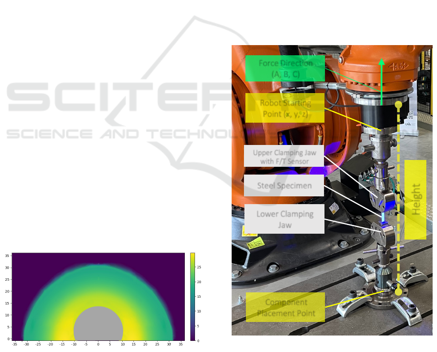
Figure 3: Visualization of a plane with the selected height
z = 130 cm of applicable pulling forces in z-direction for
the orientation of a = −90
◦
, b = 0
◦
, c = 180
◦
in robot world
coordinates. The forces are given in kN, and the reach of the
robot in the middle is given in dm.
tensile tests, the specimen is loaded in one direction
until it breaks to test material characteristics. Steel
was chosen as the material for the tensile specimen,
which needs a maximum force of up to 25 kN until it
breaks. The lower clamping jaw for the specimen de-
termines the options to mount the chosen test setup on
our clamping area. To determine the starting height
z = 130 cm for the component test, we can measure
the height of the end effector as a sum of the lower
clamping jaw plus the length of the specimen plus
the length of the end effector with the f/t torque sen-
sor mounted combined with the upper clamping jaw
(yellow part in Figure 4). Since the clamping places
the specimen perpendicular to the clamping field and
the test motion points in the direction of the clamped
specimen, we obtain a = −90
◦
, b = 0
◦
, c = 180
◦
for
the load path orientation (see the green force direction
arrow in Figure 4) with a maximum force of −25 kN
for f z as it is a pull motion in the robot base coor-
dinate system. The last step is determining the dis-
tance the robot needs to travel to ensure it can build
up the force of 25 kN over the entire distance. This
Height
Lower Clamping
Jaw
Steel Specimen
Upper Clamping Jaw
with F/T Sensor
Force Direction
(A, B, C)
Component
Placement Point
Robot Starting
Point (x, y, z)
Figure 4: Tensile test setup: Attachment of the clamping
jaws with clamped tensile specimen between the clamping
field (bottom) and the robot end effector (top), consisting of
the f/t sensor and the upper clamping jaw. The green given
force direction indicates in which direction the force is to
be applied to the specimen by the robot.
ICINCO 2023 - 20th International Conference on Informatics in Control, Automation and Robotics
380

can be done, for example, with the help of a FEM
simulation. In our example, the distance was circa
10 cm. The test motion can be entered into our pro-
gram with the help of a small UI. We have carried
out our feasibility check and the resulting component
placement with this data. Our algorithm has selected
the position x = 50 cm, y = 156 cm, and z = 130 cm
for the robot starting point, corresponding to the po-
sition shown in Figure 4. This also denotes that the
robot can apply the required forces for our chosen use
case. Finally, we performed the actual component test
to ensure that the robot could apply the forces for the
given testing motion and the calculated starting pose,
which includes the pose E and joint positions Q. For
further validation of our force model, we performed
an experimental test at different positions with differ-
ent heights. The calculated values corresponded to
the experimentally determined values with a margin
of ± 300 N. However, these are negligible unless us-
ing the test bench at its ultimate limits of the forces or
torques. In order to be able to state how exactly the
values are deviating, more research is planned, which
will be described in more detail in the next section.
6 CONCLUSION
One challenge of robot-based component testing is
specimen placement since industrial robots cannot
achieve all forces or torques in every position. Our
CASP (Computer Aided Specimen Placement) ap-
proach for robot-based component testing solves this
challenge by calculating a position for the specimen
placement where the robots can test it. We first
extended our developed model for testing motions,
which includes load paths consisting of forces and
torques, the corresponding directions, and the start-
ing point to be determined by the testing motion. A
further advantage of this model is the representation
of superimposed loads that only a few standard test
rigs can muster. Moreover, we have developed a
description and storage format for robot forces and
torques depending on the robot’s orientation and po-
sition. With the help of the combination of these two
developments, we have presented an algorithm that
performs an automatic feasibility check for the re-
quired test motions and calculates the automatic spec-
imen placement. In our case study, we briefly ex-
plained our testing facility and evaluated the compo-
nent placement by choosing a classical use case for
material testing (standardized tensile tests). Our ap-
proach automatically calculated a placement for the
test specimen of this use case, and we successfully
performed the actual test afterward. In addition, we
conducted an experimental comparison of our force
model and identified slight deviations between our
model and the actual applicable forces. An initial as-
sumption leading to this deviation is the impact of the
mounted periphery, e.g., the weight of the end effec-
tor or the cable tow, as this is currently not included
in our calculation model. In further research, we will
conduct more experimental comparisons to determine
the deviations and thus better define the boundaries
more precisely. Finally, we are investigating how
the computer aided specimen placement can be sim-
ulated, e.g., for collision detection and extended for
multi-robot component tests. For this purpose, we are
already simulating the motion to the calculated start-
ing point of the test motion with the help of ROS2,
MoveIt, and NVIDIA Isaac Sim (see Figure 1 for our
Isaac Sim Model). We also want to combine the robot
motion simulation with a physical simulation of the
specimen with the framework ORBIT to simulate the
entire test sequence later on.
ACKNOWLEDGEMENTS
This work partly presents the results of the project
WiR Augsburg which was funded by the German Fed-
eral Ministry of Education and Research (BMBF) and
the Bavarian Government.
REFERENCES
(2019). Metallic materials, Tensile testing, Part 1: Method
of test at room temperature. Standard DIN EN 6892-
1:2019, DIN Deutsches Institut f
¨
ur Normung e. V.,
Berlin, DE.
Alemzadeh, K. and Raabe, D. (2007). Prototyping artifi-
cial jaws for the bristol dento-munch robo-simulator;
’a parallel robot to test dental components and mate-
rials’. In 2007 29th Annual International Conference
of the IEEE Engineering in Medicine and Biology So-
ciety, pages 1453–1456.
Coleman, D., Sucan, I., Chitta, S., and Correll, N. (2014).
Reducing the Barrier to Entry of Complex Robotic
Software: a MoveIt! Case Study.
Filipenko, M., Poeppel, A., Hoffmann, A., Reif, W., Mon-
den, A., and Sause, M. (2020). Virtual commission-
ing with mixed reality for next-generation robot-based
mechanical component testing. In ISR 2020; 52th In-
ternational Symposium on Robotics, pages 1–6.
Hanke, J., Eym
¨
uller, C., Reichmann, J., Trauth, A., Sause,
M., and Reif, W. Software-defined testing facility
for component testing with industrial robots. ETFA,
September 06-09, 2022, Stuttgart, to be published.
Harada, K., Tsuji, T., Nagata, K., Yamanobe, N., and Onda,
H. (2014). Validating an object placement planner
CASP: Computer Aided Specimen Placement for Robot-Based Component Testing
381

for robotic pick-and-place tasks. Robotics and Au-
tonomous Systems, 62(10):1463–1477.
Haustein, J. A., Hang, K., Stork, J., and Kragic, D. (2019).
Object placement planning and optimization for robot
manipulators. In 2019 IEEE/RSJ International Con-
ference on Intelligent Robots and Systems (IROS),
pages 7417–7424. IEEE.
Howard Kuhn, D. M. (2000). ASM Handbook: Volume 8:
Mechanical Testing and Evaluation. Asm Handbook.
ASM International, 10 edition.
Kebbach, M., Grawe, R., Geier, A., Winter, E.,
Bergschmidt, P., Kluess, D., Lima, D., Woernle, C.,
and Bader, R. (2019). Effect of surgical parameters on
the biomechanical behaviour of bicondylar total knee
endoprostheses - a robot-assisted test method based on
a musculoskeletal model. Scientific Reports, 9:1–11.
KUKA AG (2023a). KR 1000 titan.
https://www.kuka.com/en-de/products/robot-
systems/industrial-robots/kr-1000-titan (accessed
on: 16.05.2023).
KUKA AG (2023b). KUKA Robot Selector.
https://www.kuka.com/en-de/products/robot-
systems/software/cloud-software/kuka-robot-selector
(accessed on 09.05.2023).
Lasi, H., Fettke, P., Kemper, H.-G., Feld, T., and Hoffmann,
M. (2014). Industry 4.0. Business & information sys-
tems engineering, 6(4):239–242.
Lozano-Perez, T., Jones, J., Mazer, E., O’Donnell, P., Grim-
son, W., Tournassoud, P., and Lanusse, A. (1987).
Handey: A robot system that recognizes, plans, and
manipulates. In Proceedings. 1987 IEEE Interna-
tional Conference on Robotics and Automation, vol-
ume 4, pages 843–849.
Mittal, M., Yu, C., Yu, Q., Liu, J., Rudin, N., Hoeller,
D., Yuan, J. L., Tehrani, P. P., Singh, R., Guo, Y.,
Mazhar, H., Mandlekar, A., Babich, B., State, G., Hut-
ter, M., and Garg, A. (2023). Orbit: A unified simula-
tion framework for interactive robot learning environ-
ments.
Nierenberger, M., Poncelet, M., Pattofatto, S., Hamouche,
A., Raka, B., and Virely, J. (2014). Multiaxial Testing
of Materials Using a Stewart Platform: Case Study of
the Nooru-Mohamed Test. Experimental Techniques,
38(2):74–83.
NVIDIA Corperation (2022). NVIDIA Isaac SDK.
https://developer.nvidia.com/isaac-sdk (accessed on
14.03.2023).
Quigley, M. (2009). ROS: an open-source Robot Operating
System. In ICRA 2009.
Siciliano, B., Sciavicco, L., Villani, L., and Oriolo, G.
(2010). Robotics: Modelling, Planning and Control.
Technische Universit
¨
at Hamburg
(2022). Hexapod Pr
¨
ufanlage.
https://www.tuhh.de/hexapod/startseite.html (ac-
cessed on 14.03.2023).
Wong, K. V. and Hernandez, A. (2012). A review of addi-
tive manufacturing. International scholarly research
notices, 2012.
ZwickRoell GmbH & Co. KG (2023a).
Pr
¨
uflabor f
¨
ur große Bauteilpr
¨
ufungen.
https://www.zwickroell.com/de/services/prueflabor-
werkstoffpruefung-bauteilpruefung/ (accessed on
21.05.2023).
ZwickRoell GmbH & Co. KG (2023b).
RoboTest R Robotic Testing System.
https://www.zwickroell.com/products/automated-
testing-systems/robotest-r-robotic-testing-system/
(accessed on: 16.05.2023).
ICINCO 2023 - 20th International Conference on Informatics in Control, Automation and Robotics
382
