
Design and Control of Wearable Ankle Robotic Device
Ali Zakaria Messaoui
1
, Mohamed Amine Alouane
1
, Mohamed Guiatni
1
, Omar Mechali
2
,
Sbargoud Fazia
1
, Zerdani Serine
1
and Belimene Cheikh Elmokhtar
1
1
Complex Systems Control and Simulators Laboratory, Ecole Militaire Polytechnique, Bordj El Bahri, Algiers, Algeria
2
Ecole Supérieur Ali Chabati, Reghaia, Algiers, Algeria
Keywords: Exoskeleton Robot, Gait Assistance, Ankle Wearable Device Design, Finite-Time Stability,
Homogeneous Sliding Mode Control.
Abstract: The primary objective of this paper is to develop an ankle wearable robotic device, which involves two
primary tasks: design and control. The design task focused on creating a comfortable, lightweight, and secure
ankle exoskeleton robot; this task was achieved using SOLIDWORKS and considering all essential factors.
For the control aspect of the exoskeleton, an Improved Optimized Homogeneous Twisting Control (IOHTC)
approach was proposed to design a robust angular position control system. To ensure the stability of the
control system, a homogeneous-Lyapunov function was used. Simulation results based on real gait data
demonstrated consistency with the theoretical foundation, and a comparative analysis based on various
performance indices confirmed the effectiveness and superiority of the proposed control law. Finally, several
simulations have been conducted on the designed model using simscape multibody link to validate it.
1 INTRODUCTION
Exoskeleton robots are mechanical devices that
human operators wear to enhance their physical
capabilities. These robots are commonly referred to
as wearable robots or powered exoskeletons. They are
categorized based on their applications, including
medical and rehabilitation, industrial, military, and
defence.
Medical and rehabilitation exoskeletons (Plaza,
2021) are designed to assist people with mobility
impairments caused by neurological or muscular
disorders, spinal cord injuries, or other conditions.
These exoskeletons provide support for walking,
standing, and other daily activities. On the other hand,
industrial exoskeletons (De Looze, 2016) are
designed to reduce the risk of injury and fatigue in
workers who perform tasks such as heavy lifting and
repetitive motions. Lastly, military and defence
exoskeletons (Farris, 2023) improve soldiers'
physical performance by providing increased
strength, agility, and endurance.
The applications of exoskeleton robots are diverse
and range from rehabilitation and physical therapy to
injury prevention and augmented reality (Mubin,
2019). Exoskeletons are used to assist patients in
regaining mobility and improving their physical
capabilities. Industrial exoskeletons can reduce the
risk of workplace injuries and assist workers when
doing demanding tasks. Additionally, exoskeletons
can be used for exploration and rescue operations, as
well as for gaming and training purposes with
augmented reality technology.
Ankle wearable robotic device is a valuable
subclass of exoskeleton robots that provides support
and assistance with ankle movements for various
populations, including patients, athletes, and soldiers
(Plaza, 2021). It is a frame that attaches to the lower
leg and foot with a motorized joint that mimics the
movement of the ankle. The device is programmable
to assist with specific movements such as dorsiflexion
and plantarflexion.
Ankle exoskeleton robots have a broad range of
applications. It is primarily used in medical
rehabilitation for patients with ankle injuries or
neurological disorders such as cerebral palsy,
multiple sclerosis, or stroke. Additionally, athletes
can use it to enhance performance and prevent
injuries during physical activities. Lastly, it has
military and defence applications, where it can help
soldiers enhance their endurance and walk and run
faster during military operations.
The design of ankle exoskeleton robots must
consider several factors, including comfort, safety,
usability, and effectiveness (Lee, 2021). Some
examples of existing ankle exoskeleton robots
include:
554
Messaoui, A., Alouane, M., Guiatni, M., Mechali, O., Fazia, S., Serine, Z. and Elmokhtar, B.
Design and Control of Wearable Ankle Robotic Device.
DOI: 10.5220/0012157200003543
In Proceedings of the 20th International Conference on Informatics in Control, Automation and Robotics (ICINCO 2023) - Volume 1, pages 554-561
ISBN: 978-989-758-670-5; ISSN: 2184-2809
Copyright © 2023 by SCITEPRESS – Science and Technology Publications, Lda. Under CC license (CC BY-NC-ND 4.0)

• H2 Ankle Exoskeleton is designed to assist
with ankle movement and improve balance
and stability for individuals with neurological
or muscular disorders (Bortole, 2015). It is
worn like a brace and provides adjustable
levels of support for different activities.
• Ankle Assist Robot is developed to assist with
ankle dorsiflexion and plantarflexion for
individuals with limited ankle mobility. It is
worn like a shoe and uses pneumatic actuators
to assist with ankle movement (Alvarez-Perez,
2020).
• Ankle Rehabilitation Exoskeleton (ARES) is
constructed to assist with ankle dorsiflexion
and plantarflexion for individuals
rehabilitating for ankle injuries or conditions.
It is worn like a brace and provides adjustable
levels of support for different stages of
rehabilitation (Plaza, 2021).
In medical and rehabilitation applications, the
control strategy is essential because the robot must
adapt to each patient's needs. The control strategy
must be capable of adjusting the level of assistance
provided by the exoskeleton based on the patient's
condition and progression. Additionally, the control
strategy must ensure that the robot is not impeding the
patient's natural movements and is not causing
discomfort or pain. Sliding Mode Control (SMC)
(Mechali, 2022) (Messaoui, 2023), among other
robust control approaches, is an active topic in the
exoskeleton robot’s community nowadays for
controlling ankle exoskeleton robot (Zhao, 2021).
The simplicity of design and the fast response are
among the benefits of such methods. In addition, it
accurately compensates for matched disturbances.
Several recent research works have focused on
synthesizing and implementing robust SMC-based
control laws for disturbance handling in wearable
robotic devices (Pont-Esteban, 2022).
The main scientific contributions of the current
research can be summed up as follows:
• The design of an ankle wearable robotic
device for gait assistance applications;
• Inspired by the homogeneity theory, an
IOHTC is proposed to deal with the fast
dynamics’ response of the joint angle position
during gait. The proposed controller allows for
mitigating the chattering of discontinuous
SMC techniques;
• It is worth mentioning that the disturbance
rejection does not require the design of an
observer or an adaptation mechanism since the
control law integrates a compensation term.
• In terms of validation, first, several
simulations of the proposed control were
conducted. The proposed controller was
applied to the designed ankle exoskeleton
using a simscape multibody link, and finally,
the suggested IOHTC method and two other
controllers are compared in this study.
The rest of this paper is organized as follows: the
second section presents the design of the ankle
exoskeleton robot; the third section introduces the
proposed control technique and control law synthesis;
the fourth section presents and discusses the different
simulation results; and finally, section five concludes
this paper and shows the future directions.
2 ANKLE EXOSKELETON
PRESENTATION AND DESIGN
2.1 Ankle Exoskeleton Presentation
The proposed ankle exoskeleton robot is designed to
assist the wearer during walking and daily life tasks,
so this robot is intended for people who have a
weakness of the lower limb muscles that can affect
the movement of the ankle, which may cause
abnormalities during gait, or for people who have an
ankle dysfunction due to neurological or stroke
disorders.
Therefore, the ankle exoskeleton robot should be
as light as possible, compatible with the wearer's
ankle and not interfere with the natural movement
desired by the user. Inspired by the movement of the
human ankle during walking, the design aims to
propose a structure of an exoskeleton robot that is
compatible with the natural movement of the human
ankle in order to assist walking in patients who have
muscle weakness in the lower limbs.
2.2 Ankle Exoskeleton Design
Generally, the human ankle has three degrees of
rotational freedom (Fig.1). Primarily, the
dorsiflexion/plantarflexion movement is the
dominant movement during walking and even during
most daily life tasks. Therefore, the proposed
structure for designing the ankle exoskeleton robot
has only one motorized joint to assist gait.
Design and Control of Wearable Ankle Robotic Device
555
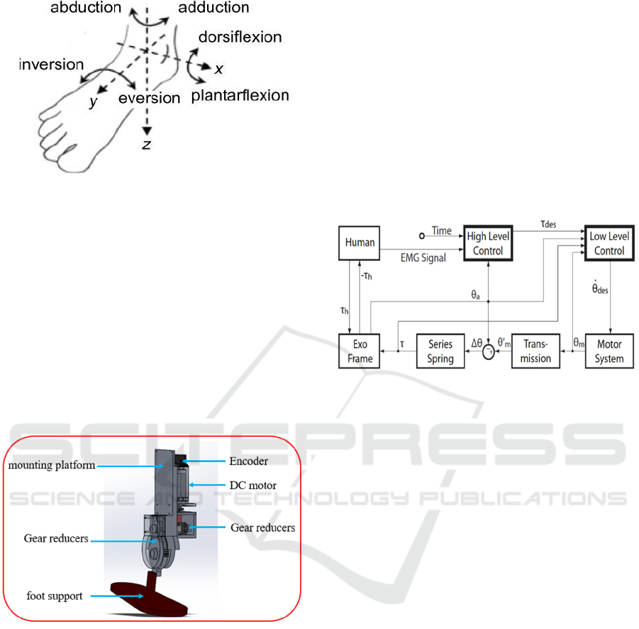
Figure 1: Human ankle morphological motion.
The dorsiflexion/plantarflexion movement of the
exoskeleton robot is ensured by a MAXON DC motor
equipped with a HEDL-5540-A12 encoder to close
the control loop. In order to increase the torque
generated by the motor, a reduction chain composed
of several gears and a worm gear has been
implemented (Fig.2). It is important to note that the
foot support is equipped with force sensors (FSR) that
serve to detect the different phases of walking; other
force sensors will be placed between the foot of the
wearer and the attaches that fix the foot with the foot
support as a safety standard (a threshold of interaction
force not to exceed).
Figure 2: Designed ankle exoskeleton robot.
3 ANKLE EXOSKELETON
ROBOT CONTROL
The specific type of control used for the ankle
exoskeleton robot will depend on various factors,
including the intended use of the exoskeleton, the
target user population, and the device's technical
specifications. Position control, velocity control, and
torque control are three standard methods of
controlling the movement of an ankle exoskeleton
robot. Position control: In position control, the
exoskeleton has to maintain a specific position or
range of motion at the ankle joint; this kind of control
is helpful for applications where precise movement is
required, such as walking or standing. Velocity
control: In velocity control, the exoskeleton is
programmed to maintain a specific speed or rate of
movement at the ankle joint. Velocity control is
practical for applications requiring a specific speed or
gait pattern, such as walking or running. Torque
control: the exoskeleton must reach a specific torque
or force output at the ankle joint. Torque control is
advantageous for applications where the user needs
assistance with tasks that require a certain level of
force, such as lifting or carrying heavy objects.
Figure 3: The exoskeleton robot control levels.
Generally, to ensure a good user experience and a
safe human-robot interaction, three levels of ankle
exoskeleton robot control work together (Fig.3),
including:
1. Low-level control: This control involves the
primary control of the exoskeleton's hardware
components, such as the motor, sensors, and
actuators. The low-level control typically
includes tasks such as signal processing,
filtering, and amplifying sensor signals, as
well as motor control algorithms for
controlling the exoskeleton's movement.
2. Mid-level control: This level of control
involves coordinating the exoskeleton's
movements with the user's movement. The
mid-level control typically includes gait
pattern recognition, motion planning, and
trajectory generation. Mid-level control aims
to ensure that the exoskeleton moves in a
natural and
3. coordinated way with the user's own
movements.
4. High-level control: This level of control
involves overall system management and
decision-making. The high-level control
typically includes user intention recognition,
task-level planning, and human-machine
interface design. High-level control aims to
ensure that the exoskeleton operates safely and
ICINCO 2023 - 20th International Conference on Informatics in Control, Automation and Robotics
556

efficiently while providing the user with the
intended level of assistance.
This work will focus on low-level position control
of the proposed ankle exoskeleton robot. For this
purpose, we propose using Improved Optimized
Homogeneous Twisting Control (IOHTC) for ankle
trajectory tracking during gait.
3.1 Preliminaries
Lemma 1. (Xu, 2017). Consider the following system
𝑥=
𝑓
(
𝑥
)
, 𝑥
(
0
)
=𝑥
, 𝑥∈
ℝ
(1)
If there exist C
Lyapunov function 𝑉
(
𝑥
)
:D→ℝ
and some real constants 0<𝑐<∞ and 0<𝛼<1,
such that 𝑉
(
𝑥
)
≤−𝑐𝑉
(
𝑥
)
, then system (1) is
finite-time stable for any given 𝑥
(
𝑡
)
∈D
⊆D.
3.2 Control Problem Statement
The differential equations governing the actuator
dynamics of the exoskeleton in the presence of
external disturbances are given as:
𝜃
=
𝑘
𝑅𝐽
𝑢
−
𝑅𝑏
𝑘
+𝑘𝜃
+𝑑
(2)
Where 𝑅,𝑘,𝐽,𝑏 are the actuator parameters, and 𝜃
presents the actuation angular position. In order to
elaborate an adequate control model of the actuator,
state-space representation can be used to reformulate
the mathematical model as
x
= x
,
x
=
𝑘
𝑅𝐽
−
𝑅𝑏
𝑘
+𝑘𝜃
+𝑢
+𝑑
,
(3)
where x≝
𝜃𝜃
∈ ℝ
is the state vector.
Consequently, the design of the control law follows
from the perturbated second-order nonlinear system
below:
where 𝑋
≝
𝜒
𝜒
∈ ℝ
is the vector of
states, and 𝜒
≝𝜃, 𝜒
≝𝜃
, 𝑢
≝𝑉∈ ℝ is the
control input, 𝒴
≝𝜃∈ ℝ is the controlled output,
and the uncertain function 𝑑
∈ ℝ stands for the
total lumped disturbances, i.e., unmodeled dynamics
and external load perturbations. The functions
𝑓
(
𝜒
,𝑡
)
,𝑔
are defined as:
⎩
⎨
⎧
𝜒
(
𝑡
)
=𝜒
(
𝑡
)
,
𝜒
(
𝑡
)
=
𝑓
(
𝜒
,𝑡
)
+𝑔
𝑢
(
𝑡
)
+𝑑
(
𝑑
,𝑑
,𝑡
)
,
𝒴
(
𝑡
)
=𝜒
(
𝑡
)
(4)
𝑓
(
𝜒
,𝑡
)
=−
𝑅𝑏 + 𝑘
𝑅𝐽
𝜃
(
𝑡
)
.𝑔
≝
𝑘
𝑅𝐽
(5)
Definition 1. (Robust tracking control problem). The
considered control problem of our study consists of
designing robust finite-time SMC laws 𝒖
𝜽
for the position
control affected by perturbations in (4), such that: (i) The
position tracking error tend to the origin in finite-time, i.e.,
for ∀𝒆
𝟏
𝜽
(
𝒕
)
≝ 𝜽
(
𝒕
)
−𝜽
𝒅
(
𝒕
)
, there exist a constant 𝑻
𝜽
,
such that: 𝐥𝐢𝐦
𝒕→𝑻
𝜽
𝒆
𝟏
𝜽
(
𝒕
)
=𝟎,∀𝒕>𝑻
𝜽
, where 𝜽
𝒅
is the
desired reference signal for the position system. (ii) The
controller must ensure robustness against uncertainties and
disturbances. (iii) The control signal is chattering-free.
3.3 Control Design and Stability
Analysis
3.3.1 Control Design
Let the position tracking error and its dynamics be
defined as
𝑒
(
𝑡
)
≝𝜃
(
𝑡
)
−𝜃
(
𝑡
)
,
𝑒
(
𝑡
)
≝𝜃
(
𝑡
)
−𝜃
(
𝑡
)
.
(6)
The derivatives of the above expressions are
given as
𝑒
=𝑒
,
𝑒
=𝜃
−𝜃
.
(7)
The basic Twisting Control (TC) algorithm is given as
𝑢
=−𝑘
𝑒
−𝑘
𝑒
+𝜗
,
𝜗
=−𝑘
𝑒
−𝑘
𝑒
.
(8)
Remark 1. It has been shown in work (Falcón R. R.,
2019) that the TC controller generates a higher
frequency, i.e., chattering, in its control signal, which
limits its application in practice. Therefore, to
improve its performance, we propose to: (i) Design a
smooth hyperbolic function to mitigate the chattering
effect as ℋ𝑒
≝𝑒
tanh𝑒
𝜐
⁄
, and
ℋ
(
𝑠
)
≝
(
𝑠
)
tanh
(
𝑠
𝜐
⁄)
; (ii) Integrate the
following sliding function 𝑠
in the basic TC’s
algorithm: 𝑠
=𝑒
+𝑘
𝑒
to enhance its robustness.
Therefore, by introducing the following control
law for the actuator system
⎩
⎪
⎪
⎨
⎪
⎪
⎧
𝑢
≝−𝑘
𝑒
ℋ𝑒
−𝑘
|
𝑠
|
ℋ
(
𝑠
)
+𝜗
,
𝜗
≝−𝑘
𝑒
ℋ𝑒
−𝑘
|
𝑠
|
ℋ
(
𝑠
)
,
𝑠
=𝑒
+𝑘
𝑒
.
(9)
Then the final actuator controller is formulated as
Design and Control of Wearable Ankle Robotic Device
557

𝑢
=
𝑔
−𝑘
𝑒
ℋ
𝑒
−𝑘
|
𝑠
|
ℋ
(
𝑠
)
+𝜗
−
𝑓
(10)
3.3.2 Stability Analysis
Theorem 1. Consider the nonlinear perturbated
actuator system (4) and the designed control law 𝑢
given in (9). Then, the position tracking errors are
globally finite-time stable at the origin.
Proof. we consider the stability proof of the
position. The closed-loop dynamics for the position
variable 𝜃 can be described as
⎩
⎪
⎪
⎪
⎨
⎪
⎪
⎪
⎧
𝑒
=𝑒
,
𝑒
=−𝑘
𝑒
ℋ𝑒
−𝑘
|
𝑠
|
ℋ
(
𝑠
)
+𝜍
,
𝜍
=−𝑘
𝑒
ℋ𝑒
−𝑘
|
𝑠
|
ℋ
(
𝑠
)
−𝜃
(
)
,
𝑠
=𝑒
+𝑘
𝑒
.
(11)
where 𝜍
=𝜗
−𝜃
. The third expression in (10) can
be associated with differential inclusion (DI) 𝜍
∈
−𝑘
𝑒
ℋ𝑒
−𝑘
|
𝑠
|
ℋ
(
𝑠
)
+
−𝜆,𝜆
.
Therefore it is associated with DI 𝑥∈𝐹
(
𝑥
)
where the
set valued map 𝐹 is given by 𝐹
(
𝑥
)
=𝑦∈ℝ
|𝑦=
𝑒
,𝜍
,𝜌
, for all 𝜌∈−𝑘
𝑒
ℋ𝑒
−
𝑘
|
𝑠
|
ℋ
(
𝑠
)
+
−𝜆,𝜆
⊂ℝ. This DI is
homogeneous of degree 𝑞
=−1 with weights 𝑟
=
3,2,1
[10].
Let the following candidate Lyapunov function be
proposed for system (10)
𝑉
𝑒
,𝑒
,𝜍
=𝛼
𝑒
+𝛼
𝑒
𝑠
+𝛼
|
𝑠
|
+𝛼
𝑒
|
𝜍
|
ℋ
(
𝜍
)
−𝛼
𝑠
𝜍
+𝛼
|
𝜍
|
,
(12)
where 𝛼
=
𝛼
,…,𝛼
∈ ℝ
,𝑗=1,6
is a vector of
coefficients. The time derivative of 𝑉
𝑒
,𝑒
,𝜍
is
computed by
𝑉
=
ℳ
=𝛽
𝑒
+𝛽
𝑒
sign
(
𝑠
)
−𝛽
sign
𝑒
𝑠
+𝛽
sign
𝑒
sign
(
𝑠
)
+𝛽
|
𝑠
|
−𝛽
𝑒
𝜍
+𝛽
𝑒
|
𝜍
|
−𝛽
𝑒
sign
(
𝑠
)|
𝜍
|
−𝛽
sign
(
𝑠
)
𝜍
−𝛽
𝑠
sign
(
𝜍
)
+𝛽
sign
𝑒
𝑠
|
𝜍
|
−𝛽
𝑒
|
𝜍
|
−𝛽
sign
𝑒
𝜍
−𝛽
sign
(
𝑠
)
𝜍
+𝛽
|
𝜍
|
+𝛽
sign
𝑒
sign
(
𝜍
)
+𝛽
sign
𝑒
sign
(
𝜍
)
.
(13)
where 𝛽
=𝛼
𝑘
,𝛽
=𝛼
𝑘
,𝛽
=
𝛼
,𝛽
=
𝛼
𝑘
,𝛽
=
𝛼
𝑘
−𝛼
,𝛽
=𝛼
,𝛽
=
2𝛼
𝑘
,𝛽
=2𝛼
𝑘
,𝛽
=
𝛼
,𝛽
=𝛼
,𝛽
=
3𝛼
𝑘
,𝛽
=3𝛼
𝑘
,𝛽
=𝛼
𝑘
,𝛽
=
𝛼
𝑘
,𝛽
=𝛼
,𝛽
=5𝛼
𝑘
,𝛽
=5𝛼
𝑘
. The
Lyapunov function 𝑉
given in (8) is homogeneous of
degree 𝑚=5. Thus, there exist a continuous
homogeneous function ℳ of degree 𝑚+𝑞
=4
such that 𝑉
≤−ℳ. Hence, there exist 𝛾
>0 such
that ℳ≥𝛾
𝑉
. Therefore 𝑉
≤−𝛾
𝑉
. This
implies that the tracking error is finite-time stable at
the origin. Furthermore, since the control system is
homogeneous, the stability property is global. The
expression of the settling-time can be obtained via
solving the differential equation 𝑉
≤−𝛾
𝑉
. This
can be achieved by utilizing the separation of
variables method. Thus, by separating the variables
and then integrating both sides of the equation we get
𝑑𝑉
≤
−𝛾
𝑑𝑡
. Then, the following
expression is obtained 5𝑉
≤−𝛾
𝑡. Finally, we can
get 𝑇
≤
5
𝑉
. It follows from Lemma 1 that the
tracking error is finite-time stable. Thus, completing
the proof.
ICINCO 2023 - 20th International Conference on Informatics in Control, Automation and Robotics
558

4 SIMULATION RESULTS AND
DISCUSSIONS
4.1 Control Gain Tuning
The gains of the controller are tuned by using the
“Optimization Toolbox”. Two blocks are used to
optimize the parameters: (i) Check Step Response
Characteristics (CSRC) block; (ii) Check Against
Reference (CAR) block. In the general case, these
Figure 1: Optimization blocks integration.
two optimization blocks are inserted in the output of
the control loop (Fig.4). The CSRC block checks that
a signal satisfies the step response bounds during
simulation (Settling-time, Rise-time, % Overshoot,
and % Undershoot). CAR block checks that a signal
remains within the tolerance bounds, at steady-state,
of a reference signal during the simulation.
CSRC, CAR blocks ensure that a signal remains
within specified time-domain characteristic bounds.
In our case, these bounds are chosen for a unit step
response, as shown in Table 1.
4.2 Controller Performances
In this section, to visualize and extract the
performance of the proposed controller, we will test
its step response by using a step of 30-degree
amplitude as the desired signal at the input of the
system. Fig.5 shows the response of our system when
using the proposed controller and two other
controllers.
Figure 2: Step response.
Fig.5 clearly shows the advantages of the
proposed controller compared to the two other
implemented controllers (PID and IBSSMC). IOHTC
showed better performance with a response time
t
IOHTC
=0.22s without overshoot, while PID has a
response time t
PID
>25s, and IBSSMC has a
considerable overshoot D
IBSSMC
>33% which can
imply risks on the user (the non-respect of the limits
of articular movements).
4.3 Ankle Angular Position Tracking
During Gait
This section will test the proposed controller using
real walking data. These data have been derived from
a publicly available dataset (Embry, 2018); from this
dataset, we have recovered the evolution of the
angular position of the ankle during a real walk on flat
ground with a speed of 1m/s. This test allows us to
visualize the proposed controller's performance and
the two other implemented controllers in real ankle
joint movement tracking problem.
Figure 3: Ankle movement tracking during real gait.
In order to clearly show the difference between
the system responses using each controller, we took a
portion of data equivalent to four gait cycles and used
it as a reference signal. Figures 6 and 7 show the
desired angular position tracking and the evolution of
the error over time. Finally, we use RMSE as a metric
to compare the three controllers. The proposed
controller showed better performance with
RMSE=0.2509 deg, the PID controller has
RMSE=0.8492 deg, and the IBSSMC has
RMSE=0.5613 deg.
Figure 4: Tracking error evolution over the time.
Design and Control of Wearable Ankle Robotic Device
559
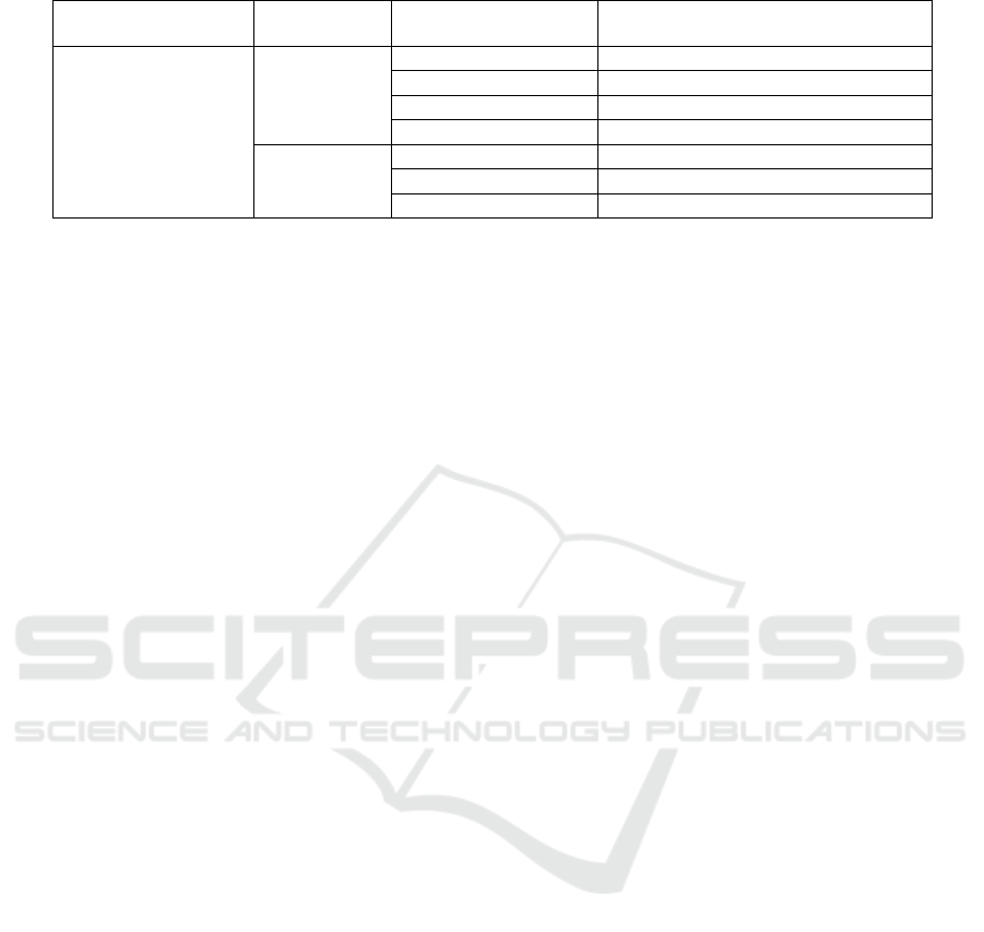
Table 1: Specified time-domain characteristic bounds for position states.
State
Optimization
Block
Characteristics Value
𝜃
CSRC
Settling-time (s) ≤2 s
Rise-time (s) ≤4 s
Overshoot (%) ≤30 %
Undershoot (%) ≤5 %
CAR
Amplitudes 1 − exp(−linspace(0,20)/2)
Absolute tolerance
eps
(/)
Relative tolerance 0.01
Several simulations using the previously
implemented controllers were performed on the ankle
exoskeleton robot SOLIDWORKS model using
simscape multibody link. The tests performed
allowed us to validate the model designed model, and
the simulations show that the ankle of the model
performs movements similar to a human ankle during
walking.
5 CONCLUSION
This work aims to achieve two main tasks for
implementing a robot exoskeleton: design and
control. Regarding the design part, an ankle
exoskeleton robot was designed using
SOLIDWORKS, considering all the essential points
for the robot to be comfortable, lightweight and
secure. Concerning the designed exoskeleton control,
we proposed an IOHTC approach to design a robust
exoskeleton angular position control. The stability of
the control system has been rigorously discussed
based on a homogeneous-Lyapunov function. Results
based on the real-data gait ankle angular position
tracking simulation are found to be consistent with
the theoretical foundations. A comparative analysis
based on various performance indices was performed
to thoroughly examine the synthesised controller's
capabilities. Results witness the effectiveness and
superiority of the proposed control law. Further
studies will address realizing the proposed
exoskeleton robot and real-world experiment and the
exploration of the development of EMG-based model
for intelligent control of this exoskeleton robot.
REFERENCES
Alvarez-Perez, M. G.-M.-S. (2020). Robot-assisted ankle
rehabilitation: A review. Disability and Rehabilitation:
Assistive Technology,, 15(4), 394-408.
Bortole, M. V.-V. (2015). The H2 robotic exoskeleton for
gait rehabilitation after stroke: early findings from a
clinical study. Journal of neuroengineering and
rehabilitation, 12, 1-14.
De Looze, M. P. (2016). Exoskeletons for industrial
application and their potential effects on physical work
load. Ergonomics, 671-681.
Embry, K. V. (2018). The effect of walking incline and
speed on human leg kinematics, kinetics, and EMG. .
IEEE DataPort, 10.
Falcón, R. R. (2019). Comparative analysis of continuous
sliding-modes control strategies for quad-rotor robust
tracking. . Control Engineering Practice, 90, 241-256.
Falcón, R., Ríos, H., & Dzul, A. (2019). Comparative
analysis of continuous sliding-modes control strategies
for quad-rotor robust tracking. Control Engineering
Practice, 90, 241-256.
Farris, D. J. (2023). A systematic literature review of
evidence for the use of assistive exoskeletons in defence
and security use cases. Ergonomics, 61-87.
Jimenez-Fabian, R. &. (2012). Review of control
algorithms for robotic ankle systems in lower-limb
orthoses, prostheses, and exoskeletons. Medical
engineering & physics, 34(4), 397-408.
Lee, T. K. (2021). Design of a 2dof ankle exoskeleton with
a polycentric structure and a bi-directional tendon-
driven actuator controlled using a pid neural network.
In Actuators . MDPI, (Vol. 10, No. 1, p. 9).
Mechali, O. X. (2022). Fixed-time nonlinear homogeneous
sliding mode approach for robust tracking control of
multirotor aircraft: Experimental validation. , . Journal
of the Franklin Institute, 359(5), 1971-2029.
Messaoui, A. M. (2023). Robust Finite-Time Control of a
Multirotor System via an Improved Optimized
Homogeneous Twisting Control: Design and
Validation. International Conference on Simulation
and Modeling Methodologies, Technologies and
Applications., (pp. 326-331). Rome, Italy.
Mubin, O. A. (2019). Exoskeletons with virtual reality,
augmented reality, and gamification for stroke patients’
rehabilitation: systematic review. JMIR rehabilitation
and assistive technologies, e12010.
Plaza, A. H. (2021). Lower-limb medical and rehabilitation
exoskeletons: A review of the current designs. IEEE
Reviews in Biomedical Engineering, 102554.
Pont-Esteban, D. S.-U. (2022). Robust Motion Control
Architecture for an Upper-Limb Rehabilitation Exosuit.
IEEE Access, 10, 113631-113648.
Xu, Q. (2017). Continuous integral terminal third-order
sliding mode motion control for piezoelectric
ICINCO 2023 - 20th International Conference on Informatics in Control, Automation and Robotics
560

nanopositioning system. IEEE/ASME Transactions on
Mechatronics, 22(4), 1828-1838.
Zhao, J. Y. (2021). Sliding mode control combined with
extended state observer for an ankle exoskeleton driven
by electrical motor. Mechatronics, 76, 102554.
Zhou, J. Y. (2021). Lower limb rehabilitation exoskeleton
robot: A review. Advances in Mechanical Engineering,
13(4), 16878140211011862.
Design and Control of Wearable Ankle Robotic Device
561
