
Validation of a Biomechanical Performance Assessment Platform
Applying an Inertial-Bpased Biosensor and Axis Vector Computation
Wangdo Kim
1,2 a
, Sean S. Kohles
3,4,5 b
, Emir A. Vela
1,2 c
and Victor Huayamave
6d
1
Ingeniería Mecánica, Universidad de Ingeniería y Tecnología -UTEC, Lima, Peru
2
Research Center in Bioengineering, Ingeniería Mecánica, Universidad de Ingeniería y Tecnología-UTEC, Lima, Peru
3
Kohles Bioengineering, Cape Meares, OR, U.S.A.
4
Division of Biomaterials & Biomechanics, School of Dentistry, and Department of Emergency Medicine,
School of Medicine, Oregon Health & Science University, Portland, OR, U.S.A.
5
Department of Human Physiology and Knight Campus for Accelerating Scientific Impact, University of Oregon,
Eugene, OR, U.S.A.
6
Department of Mechanical Engineering, Embry-Riddle Aeronautical University, Daytona Beach, FL, U.S.A.
Keywords: Biosensors, Instantaneous Axis-Angle Representations, IMU Sensors, Inertial Measurement Units, Quaternions,
Inverse Kinematics, Forward Kinematics, Instantaneous Axis of Rotation, Motion Tracking Sensors.
Abstract: Inertial kinetics and kinematics have substantial influences on human biomechanical function. A new
algorithm for IMU-based motion tracking is presented in this work. This study combines recent developments
in improved biosensor technology with mainstream motion-tracking hardware to measure the overall
performance of human movement based on joint axis-angle representations of limb rotation. This study
proposes an alternative approach to representing three-dimensional rotations using a normalized vector around
which an identified joint angle defines the overall rotation, rather than a traditional Euler angle approach.
Contrast the procedure of Euler angles with the procedure of Axis angle, Euler angles force the body to move
along a certain route which it had arbitrarily chosen but which the body had not chosen; in fact, the body
would not take any of its routes separately, though it would take all of them together in the most embarrassing
manner-goal-directed behavior. But axis angle had no preconceived scheme as to the nature of the movements
to be expressed. Although the axis-angle representation requires vector quotient algebra (quaternions) to
define rotation, this approach may be preferred for many graphics, vision, and virtual reality software
applications. Elbow flexion and extension motion was used to validate the analytical methods. The results
suggest that the novel approach could reasonably predict a detailed analysis of axis-angle migration. The
described algorithm could play a notable role in the biomechanical analysis of human joints and offers a
harbinger of IMU-based biosensors which may assess the control of skilled manipulation.
1 INTRODUCTION
Human motion capture systems, constructed from
Inertial Measurement Units (IMUs), have been the
subject of recent development and validation. Lapresa
et al. (2022) presented the validation of inertial
systems using an anthropomorphic robot (Lapresa et
al., 2022). These approaches rely on measuring the
three-dimensional linear and angular positions and
accelerations of subject joints and limbs generated by
a
https://orcid.org/0000-0003-0527-5129
b
https://orcid.org/0000-0002-5869-7715
c
https://orcid.org/0000-0002-9397-2452
d
https://orcid.org/0000-0003-0837-6849
micro-electromechanical systems (MEMS) such as
an IMU. Effectively, an IMU is a localized biosensor
accelerometer and gyroscope estimating an object’s
biomechanical position and orientation. IMUs can be
single-point sensors or more complex single-pack
arrays when including an additional magnetometer
and sensor fusion algorithm, providing more accurate
movement data and reduced sensor drift. A common
artifact of accelerometer measurements is manifested
in velocity and displacement trajectory drift obtained
when integrating the raw acceleration record.
Kim, W., Kohles, S., Vela, E. and Huayamave, V.
Validation of a Biomechanical Performance Assessment Platform Applying an Inertial-Bpased Biosensor and Axis Vector Computation.
DOI: 10.5220/0012157900003587
In Proceedings of the 11th International Conference on Sport Sciences Research and Technology Support (icSPORTS 2023), pages 93-100
ISBN: 978-989-758-673-6; ISSN: 2184-3201
Copyright © 2023 by SCITEPRESS – Science and Technology Publications, Lda. Under CC license (CC BY-NC-ND 4.0)
93

MEMS-based IMU sensors can be used in
computer vision techniques that track the location of
a person through a combination of their pose and
orientation with applications in robotics, personal
navigation, and virtual reality. Furthermore, recent
studies confirm IMU sensor applications for human
motion analysis, enhancing biomechanics,
rehabilitation, ergonomics, and sports assessments
(González-Alonso et al., 2021). This research
includes refined quantification of human movements
and movement classification. These studies
concentrate on obtaining the kinematic Identification
of a particular activity, which helps identify
biomechanical disorders such as disease or injury, as
well as longer-term patterns of atypical
neuromuscular control. Compact, self-contained
systems for the kinematic Identification of human
motion, such as that offered by IMUs, are
independent of the subject’s mobility environment
and free of obstructions that may affect optical
position sensors (D'Amore, Ciarleglio, & Akin,
2015).
Current swing dynamic performance indices seem
to be insufficient to represent the fundamental of golf
dynamic performance because full-body models may
be easily affected by the rotation of individual
anatomical segments (Teu, Kim, Fuss, & Tan, 2006).
Recent studies have suggested that the inertia tensor,
a physical property whose values are time- and
coordinate-independent, may be an important
informational invariant haptic perception of which is
not influenced by the segment rotations. Previous
work addressing the biomechanical performance
assessment platform used an optical-based system
(Figure 1) and identified the geometric change to a
certain axis, such that if the club is rotated around this
axis through a determinate angle, the desired
movement will be effected. The perception-action
dynamic alignment between the inertia of the club
and the instantaneous axis was indexed as an
influence on the swing phase of the golf training
system (Kim, Veloso, Araújo, Machado, et al., 2013).
We found that perception and action were more
highly correlated with each other in the more skilled
player (Figure 2b) compared to the less experienced
player (Figure 2a).
The present study describes the characteristics of
an IMU wearable sensor platform that provides a
critical biomechanical parameter during the
assessment of joint disease and injury. Here, the
instantaneous axis-angle representation (IAA) of
limb function is a vector that is identified as a metric
to assist human movement analysis for use in
rehabilitation and sports. The estimation of the IAA
and its variant motion is strongly related to the joint's
functionality and ligament health (Kim, Araujo,
Kohles, Kim, & Alvarez Sanchez, 2020) as well as
the overall performance of locomotion perception and
motor control (Kim, 2020). Joint kinematics depend
on a postural balance or equilibrium, meaning that the
components of the resultant moment about the axis of
rotation sum to zero. In this work, we confirm the
accuracy of IMU-based inverse kinematics and
forward kinematics as applied to upper limb
movement.
Figure 1: Position of attached markers on the body of the
subject that adopted the stance at the instance of the club
addressing the ball. The separate panel depicts individual
markers attached to the hand. The labeled markers were
used to build an anatomical reference frame within which
the grip reference frame was coincident at the beginning of
the downswing. The origin of the global frame coincides
with the first COP location of the left foot.
The specific objective of this work is to present a new
algorithm for Inertial measurements unit (IMU)-
based motion tracking with quaternions. Axis-angle
representation for rotation, instead of representing a
3D rotation using a sequence of rotations around the
sensor coordinates system, as Euler angles do, the
axis-angle representation uses a normalized vector S
around which the rotation is defined by some angle θ
and can track a sequence of events in terms of a one-
one correspondence of IAA. Although the IAA is not
fixed, it is indeed moving about in such an
embarrassing manner that has unity relative to the
posture and behaviors of the subject being
considered.
There are two main advantages to using the axis
angle representation for describing limb kinematics.
The first is that they allow a global description of rigid
body motion that does not suffer from singularities
due to local coordinates. Such singularities are
inevitable when one represents rotation via Euler
icSPORTS 2023 - 11th International Conference on Sport Sciences Research and Technology Support
94
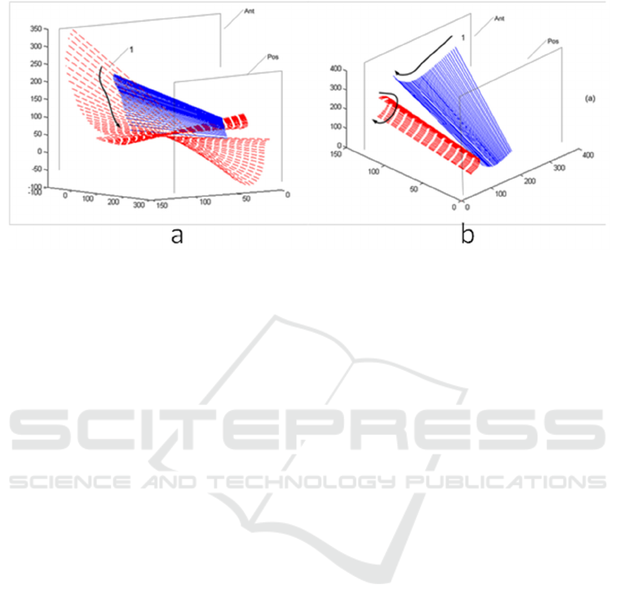
Figure 2: (a), (b). Player A, the novice golf player, produced a three-dimensional spatiotemporal view on the instantaneous
axis-angle (IAA, solid lines) and the instantaneous principal axes of inertia (e3, dashed lines) for small motion steps (300Hz)
that were projected onto the posteromedial side of the player (a). The endpoints of axes are at the intersections with anterior
(Ant) and Posterior (Pos) planes, which are located 100 and 300 cm off the origin of the global frame. The first axis, indicated
by 1, represents the beginning of the downswing. The arrow indicates where the subsequent axes have migrated at every
0.0333 second of time step (units in cm).
Player B, the skilled player, produced a three-dimensional spatiotemporal view on the instantaneous axis-angle (IAA, solid
lines) and the instantaneous principal axes of inertia (e3, dashed lines) for small motion step (300Hz) that were projected onto
the posteromedial side of the player (a) and onto the superior side of the player (b). In an effort to verify positioning perception
and action relation in time-sequence of motion data, the club IAA is shown to be regularly projective to the e3. This
representative analysis indicates a close connection (Spatial-temporal representation of IAA versus the e3) during the
downswing for player B.
angles. The second advantage is that the axis-angle
provides a very geometric description of rigid motion,
which significantly simplifies the analysis of
biomechanisms and is handy for describing the
kinesthesis, "feeling of movement," in all skeletal and
muscle structures. The axis vector is not moving
instantaneously, occupying a stationary axis in the
global frames.
2 MATERIAL AND METHODS
2.1 Inertial Measurement Unit Device
and Model Foundation
The newest generation of cost-efficient inertial
motion trackers features a lightweight design,
wireless connectivity (Bluetooth Low Energy, BLE),
and robust sensor fusion algorithms to provide
accurate data for human movement applications
(DOT Wearable Sensor, Xsens Technologies B.V.,
Enschede, the Netherlands). Software manipulation
tools are provided (Software Development Kit, SDK)
to facilitate the customization of mobile applications
based on the available output data, thereby allowing
developers to integrate the sensor into a wide range of
solutions. Robust algorithms (Strap Down
Integration, SDI) and a sensor fusion framework
(Xsens Kalman Filter Core, XKF) run onboard the
sensor to provide accurate physical orientation
estimates and minimize the effects of magnetic
distortion (González-Alonso et al., 2021).
The IMUs applied in this work contain MEMS
type gyroscopes, accelerometers, and
magnetometers. These individual sensor signals are
fused through a statistical estimation framework to
obtain three-dimensional (3D) limb and joint
orientation. The output provided by the three main
device components is then fed into the signal
processing pipeline. The two main algorithms noted
above are run onboard the motion tracking sensor
(Schumacher, 2006). The sensors are primarily
designed to connect to mobile devices such as
smartphones that must be BLE-capable (Figure 3).
Before describing the output data, it is prudent to
present the types of reference systems used in this
paper. Data shall be expressed in terms of local
(Sensor Coordinate System, SCS) and global, earth-
fixed (Global Reference Coordinate System, GRCS)
coordinate systems. The SCS is a right-handed,
Validation of a Biomechanical Performance Assessment Platform Applying an Inertial-Bpased Biosensor and Axis Vector Computation
95

Figure 3: Wireless communication between the sensors and
a mobile device was used in this study.
Cartesian coordinate system that is body-fixed within
each sensor identified with lowercase x, y, and z axes
(Figure 4). The local earth-fixed RC is also defined as
a right-handed, Cartesian coordinate system with the
following global orientations:
X positive to the East (E).
Y positive to the North (N).
Z positive when pointing Up (U)
Figure 4: The local sensor coordinate system (SCS) is
associated with the sensor as indicated by the (x,y,z)
Cartesian coordinate system, while the global reference
coordinate system (GRCS) is matched to the elbow joint
and anatomic orientation as indicated by the (X, Y, Z)
Cartesian coordinate system. Since the SCS is not aligned
with the GRCS in this anatomic configuration, the data
measured by the SCS is transformed through vector algebra
by applying the unit quaternion cos
𝜋
4
,0,0,sin
𝜋
4
,
which rotates data in SCS by 90 degrees about the Z axis.
This coordinate system is known as East-North-Up
(ENU) and is the standard framework in inertial
navigation for aviation and geodetic applications.
Note that positive global orientations can be
established for any application while maintaining the
right-hand configuration, i.e., X positive to the South
(S).
The wearable sensors produce instantaneous 3D
coordinate axis orientation and acceleration data. The
data available for the experiment can be classified
into two categories: inertial data and sensor fusion
data. The inertial data is comprised of linear
acceleration (units of m/s
2
) and angular velocity
(units of ◦/s) as provided in the SCS. These IMU-
based sensors output angular velocities as a direct
measurement from the internal gyroscopes. The 3D
orientation output takes the quotient of the axis
vectors as unit quaternions. The orientation can be
represented by a normalized quaternion, q = [W X Y
Z] with W being the real component and X, Y, Z as
the imaginary global coordinate components. This
sensor output is within the ENU localized global
reference coordinate system. The output IMU
measurement vector 𝑆
contains the individual
measurements stacked together as ten state variables:
𝑆
𝑎
, 𝑎
, 𝑎
, 𝜛
, 𝜛
, 𝜛
, 𝑞
, 𝑞
, 𝑞
, 𝑞
(1)
The optimal filtering problem is then to determine the
angular acceleration state variables, 𝛼
, 𝛼
, 𝛼
as
well as their numerical derivatives as the angular
velocity vector components 𝜔
, 𝜔
, 𝜔
. Further, the
problem is then constructing the new state variables,
which provide the best match with the data within
𝑆
but also have a degree of numerical smoothness.
The regularization method is then applied to solve
this numerical challenge (Trujullo & Busby, 1997).
In this study, we estimated the identified state
variables by applying L-curve Tikhonov
regularization filtering (TRF). The TRF algorithm
was previously applied in the optimization of
smoothing parameters (Ancillao, Vochten, Verduyn,
De Schutter, & Aertbeliën, 2022) during multiscale
cell-tissue level (Kim, Tretheway, & Kohles, 2009)
and joint level (Kim, Kim, Veloso, & Kohles, 2013)
biomechanical analyses. As a result of the TRF,
thirteen numerically smoothed state variables are then
present in the filtered vector 𝑆
:
𝑆
𝑎
, 𝑎
, 𝑎
, 𝜛
, 𝜛
, 𝜛
, 𝑞
, 𝑞
,
𝑞
,
𝑞
, 𝛼
, 𝛼
, 𝛼
(2)
The data in this application was recorded through
local resources (VR Motion Laboratory, Department
of Mechanical Engineering, UTEC, Lima, Peru). One
healthy, well-trained subject (1 man) gave his written
informed consent to participate in this study.
It has frequently been assumed in previous
methods that the point of observation for motion is
unoccupied because it is measured in a Sensor
Coordinate System (SCS), while the point of
observation in this work is occupied in global
icSPORTS 2023 - 11th International Conference on Sport Sciences Research and Technology Support
96

reference coordinate systems (GRCS.) When a point
of observation is occupied, there is also information
to specify the motion of himself, and the limb of the
person in action instantaneously occupies some
portion of the space in a way that is unique to the
person as presented as the instantaneous axis-angle
representation (IAA.) This information is unique to
that person. The IAA is not moving and stationary in
the GRCS, occupying the specific axis in the freedom
space. Therefore, the innovation brought by this
research is to propose the measure of the feeling of
the self-movement, i.e., proprioception, in terms of
the IAA, meaning that it specifies the self-movement
as distinguished from an object moving in the
environment.
2.2 Inverse Kinematic Solutions Using
Quaternions
Our solution method is based on an axis-angle
representation by applying vector algebra quaternions
as a motion operator. All rotating screw motions are
represented as a rotation about an axis with respect to
the global GRCS. Two quaternions describe general
movement positioning: one for orientation and the
second for translation.
All the data processing was implemented in a
commercial programming and computing platform
(MATLB, The MathWorks, Natick, MA, USA).
Here, the module “Quaternion.m” was applied
(Tincknell, 2023). Quaternion.m implements
quaternion mathematical operations, including three-
dimensional rotations, transformations, and
numerical propagation of the governing equations of
rotational motion, most of which are fully vectorized.
Quaternions represent complex numbers within a
four-dimensional vector space (rank 4) over a real
number field (Kuipers, 1999). A quaternion is
generalized as
𝑞𝑤𝑥𝑖𝑦𝑗𝑧𝑘
𝑞
, 𝑞
, 𝑞
, 𝑞
(3)
or
𝑞
𝑞
, 𝒒
𝒗
(4)
where 𝑞
represents a scalar and 𝒒
𝐯
𝑞
, 𝑞
, 𝑞
represents a vector. A quaternion of 𝒒
𝐯
0 is called
a real quaternion, and a quaternion of 𝒒
𝟎
0 is
identified as a pure quaternion. Multiplication of two
quaternion vectors can be expressed as
𝑞
⊗𝑞
𝑞
𝑞
−𝑞
⋅𝑞
, 𝑞
𝑞
𝑞
𝑞
𝑞
𝑞
(5)
where the symbols “ ⊗ ”,” ⋅ ”,” ” denote the
quaternion product, dot product, and cross product
actions, respectively. Quaternion multiplication is not
considered commutative. The conjugate of the
quaternion can be expressed as:
𝑞
∗
𝑞
, −𝒒
𝒗
𝑞
, −𝑞
, −𝑞
, −𝑞
(6)
and thus defining the quaternion norm
‖
𝑞
‖
as:
|
𝑞
|
𝑞⊗𝑞
∗
𝑞
𝑞
𝑞
𝑞
(7)
With the relationship
‖
𝑞
‖
1, a unit quaternion is
present whereby any quaternion
𝑞
can be
normalized by dividing by its norm. The inverse of a
quaternion is then expressed as:
𝑞
1
|
𝑞
|
𝑞
∗
𝑎𝑛𝑑
‖
𝑞
‖
0
(8)
and thereby for a unit-quaternion, the relationship is
reduced to:
𝑞
𝑞
∗
(9)
A unit quaternion can be further defined as a vector
rotation operator. Rotation about a unit axis 𝜔 with
an angle 𝜃 is then defined by the axis-angle
representation (Figure 5).
𝑞cos
𝜃
2
,sin
𝜃
2
𝜔
(10)
Figure 5: Graphical axis-angle representation for vector
rotations. The approach described here uses a normalized
quaternion q around which the rotation is defined by four
kinematic variables instead of three. Applications include
computer-aided graphics, vision, and virtual reality
computation.
2.3 Biomechanical Orientation
Tracking with Quaternions
Earlier work has demonstrated how human
perception and motor control interact continuously
between external physical systems (Gibson, 1979).
The axis-angle representation effectively establishes
a global description of the individual as a rigid body
during environmental interactions and avoids
mathematical singularities due to the use of the local
Validation of a Biomechanical Performance Assessment Platform Applying an Inertial-Bpased Biosensor and Axis Vector Computation
97

coordinates. The benefits of using quaternions during
axis-angle representation as described in the
presented approach are the well-defined sets of
operations for vector addition, multiplication, and
interpolation while converting the representations
directly to rotational matrices. Such singularities are
inevitable when representing rotations traditionally
via Euler angles.
A general rigid-body transformation has 6 degrees
of freedom (DOF) accounting for linear and angular
translations or as defined here: 3 DOF for orientation
and 3 DOF for translation. A unit-quaternion can be
used as a rotation operator as shown in Equation 10
and Figure 3. A vector 𝒗 can be transformed into a
vector 𝒘 such that:
𝒘 = 𝑞⊗𝒗⊗𝑞
∗
(11)
where 𝑞 is a unit quaternion and 𝒗 is a pure
quaternion. The unit quaternion can be used to
transform a vector, but not through rigid
transformation. Therefore, an alternative quaternion
will implement translation:
𝑡 = 𝒑−𝑞⊗𝒑⊗𝑞
∗
(12)
Where 𝒑 is the position vector of an arbitrary point on
the axis within a pure quaternion.
In this study, we use the axis-angle representation
to obtain the inverse kinematics solution of the elbow
during simple flexion and extension within the
healthy range of motion of upper limb movement.
The immediate objective is to identify the forward
kinematics of the hand. For this purpose, it suffices to
identify the values of the axis-angle of the elbow joint
and its location with respect to the GRCS system. The
estimation of the IAA representation of limb
movement, also known as a biomechanical screw axis
(Ball, 1900), can play a notable role in the
biomechanical analysis of biological joints (healthy,
diseased, and injured). We assume that the amplitude
of the angle of the instantaneous axis is minute, in
conformity with a small angle assumption when
combined in the same manner as force values.
3 RESULTS
We demonstrate the described IMU-based approach
by applying the axis-angle representation of healthy
upper limb movements. These experiments: (i)
demonstrate the calculation of the IAA and the
analysis of IAA migration using quaternion
operators; (ii) check the accuracy of both the IMU-
based inverse kinematics and forward kinematics. A
single male adult subject was used to validate the
mathematical approach with data functional anatomic
data produced during elbow flexion-extension
postures of the upper limb within the sagittal plane of
motion. The UTEC human-subjects ethics committee
approved the data collection.
The forward kinematics was performed in that
sensor trajectories were reconstructed as x,y, z
Cartesian coordinates with the help of the IAA. The
RC frame was defined for the elbow joint as follows
(Figure 4): The origin location is the midpoint of the
projection between the medial and lateral bony
aspects of the distal humerus. The X-axis defines the
lateral aspects of the elbow joint. The X-axis is also
coincident with the South (S) orientation according to
the ENU global reference coordinate system, the Y-
axis is positive to the East (E), and the Z-axis is
positive when pointing up (U).
Data were generated by the IMU accelerometer
and gyroscope, as provided in the sensor-fixed frame
(SCS) and combined through a sensor fusion
algorithm measuring the orientation with respect to
the global reference frame (GRCS). Therefore, it is
necessary to align the SCS frame in which three linear
accelerations and three rotational rate gyroscopes are
measured to the global coordinates as described
above, allowing the IAA to be computed by the global
system.
The virtual sagittal plane was defined relative to
the geometric representation of the IAA from the
geometric center (Figure 6). This allows us to assess
variability in the direction of the functional IAA
during the flexion-extension movement of the
forearm. In addition, the intersection of the functional
IAA with this plane was analyzed, while the
migration of IAA was observed for small motion
steps (acquired at 60 Hz).
Contrast the procedure of Euler angles with the
procedure of Axis angle, Euler angles tried to force
the body to move along the certain route which it had
arbitrarily chosen but which the body had not chosen;
in fact, the body would not take any one of its routes
separately, though it would take all of them together
in the most embarrassing manner—goal-directed
behavior. But axis angle had no preconceived scheme
as to the nature of the movements to be expressed. A
subject simply found the body in a certain position,
A, and then he coaxed the body to move, not in this
way or in that particular way, but any way the body
liked to any new position B.
icSPORTS 2023 - 11th International Conference on Sport Sciences Research and Technology Support
98

Figure 6: A sequence of IAAs from the single human
subject elbow is represented relative to the origin of the
global frame (units in meters, m).
Once the IAA was defined, forward kinematics
obtained the vector trajectories (Figure 7). Finally, the
position of the end effector, the IMU sensor located
in the palm of the subject’s hand, is given by
trajectories as viewed in the oblique and on the
sagittal plane.
4 CONCLUSIONS
In theoretical terms, inverse kinematics, which in
itself is ruled by an IAA, is formed to visualize the
migration of biomechanical action. Another piece of
information provided by forward kinematics as ruled
by the end effector is formed by visualizing the
migration of the motion at the distal or proximal ends
of the limb itself. In this way, the characteristics of
the elbow motion can be estimated intuitively based
on the shape and alignment relative to each of the
limb segments. From a mechatronic perspective, we
use position and orientation data to control the end
effector of a robotic arm. From that application,
identifying the joint variables that generate that
desired position and orientation will ultimately
control the end effector. However, human movement
control is continuous and processed concurrently with
afferent and efferent inherent modulation.
Limitations of this study are that one IMU sensor
was used during the activity of a single subject. The
optimal system for joint biomechanics should be
characterized using two IMUs where each sensor is
worn at the proximal and distal segments containing
the target joint. Future research will focus on
increasing the use of IMUs when defining limb
movements while studying the model performance in
clinical and laboratory settings.
Figure 7: The elbow IAA trajectories as viewed at the
oblique angle (a) and the sagittal plane containing the
motion of flexion and extension (b). (units in meters, m).
By using the traditional optical-based motion
tracking system, we have characterized the concept of
a "knee axis" and further the concept of "invariant.
(Kim & Vela, 2021; Kim, Veloso, Araújo, Vleck, &
João, 2013)" We found that the line of the ground
reaction force (GRF) vector is very close to the knee
instantaneous axis (KIA). It aligns the knee joint with
the GRF such that the reaction forces are torqueless.
This insight shows that locating KIA is equivalent to
the dynamic alignment measurement. This method
can be used for the optimal design of braces and
orthoses for the conservative treatment of knee
osteoarthritis. Having validated the axis-angle with
the optical-based system, we applied the same
approach with the imu-based system to track the
occupied motion of the subject.
The invariant combination of the axis-angle
representation could open a new era of quantifying
biomechanical perception-action systems as
interactions with the natural or built environment.
The overall performance metrics of many motor
activities could be extended to real-world and clinical
settings within multiple spatial and temporal
frameworks. Further, this approach may then be
extended to understanding the causal nature of
biomechanical injury and disease, especially that
associated with inertial kinetics and kinematics.
The kinesthesis, the awareness of one's own
motion, cannot be measured in a sensor coordinate
system (SCS.) However, they have unity relative to
the posture and behavior of the subject being
(a)
(b)
Validation of a Biomechanical Performance Assessment Platform Applying an Inertial-Bpased Biosensor and Axis Vector Computation
99

considered. The results exert goal-directed feedback
control by using the IAA to guide our motion
continuously. Our assumption is that goal-directed
feedback could be applied to many more
rehabilitation application routines. Real-time posture
correction and motion change instruction could
ultimately optimize motor learning, reducing injuries
caused by excessive motion and bad postures.
Therefore, the shape of the IAA surface relative to the
goal-directed behavior of the performer can be
regarded as the “genome” of golf swing performance.
ACKNOWLEDGEMENTS
This study was funded by PROCIENCIA under
contract N° PE501080681-2022-PROCIENCIA
Proyectos Especiales: Proyectos de Investigadores
Visitantes, the MIT-Peru UTEC Seed Fund,
“Development of Proper Tunnel Syndrome
Placement Device to Avoid Impingement”, the UTEC
Fondo Semilla 2022, “Aprendizaje Perceptivo de los
Movimientos de las Piernas y Pateo de Infantes con
Espina Bífida utilizando un Sistema de
Entrenamiento de Realidad Virtual.”, the National
Institutes of Health, USA (Grants: R03 DE014288,
R15 EB007077, and P20 MD003350), and the US
National Science Foundation CAREER award
CMMI-2238859.
REFERENCES
Ancillao, A., Vochten, M., Verduyn, A., De Schutter, J., &
Aertbeliën, E. (2022). An optimal method for
calculating an average screw axis for a joint, with
improved sensitivity to noise and providing an analysis
of the dispersion of the instantaneous axes. Plos one,
17(10), e0275218.
Ball, R. (1900). A Treatise on the Theory of Screws:
Cambridge University Press.
D'Amore, N., Ciarleglio, C., & Akin, D. L. (2015). Imu-based
Manipulator kinematic identification. Paper presented at
the 2015 IEEE International Conf. on robotics and
automation (ICRA).
Gibson, J. J. (1979). The Ecological Approach to Visual
perception: Houghton Mifflin.
González-Alonso, J., Oviedo-Pastor, D., Aguado, H. J., Díaz-
Pernas, F. J., González-Ortega, D., & Martínez-Zarzuela,
M. (2021). Custom IMU-based wearable system for
robust 2.4 GHz wireless human body parts orientation
tracking and 3D movement visualization on an avatar.
Sensors, 21(19), 6642.
Kim, W. (2020). The Knee Proprioception as Patient-
Dependent Outcome Measures within Surgical and Non-
Surgical Interventions Proprioception: IntechOpen.
Kim, W., Araujo, D., Kohles, S. S., Kim, S.-G., & Alvarez
Sanchez, H. H. (2020). Affordance-Based Surgical
Design Methods Considering Biomechanical Artifacts.
Ecological Psychology, 1-15. doi:10.1080/10407413.
2020.1792782
Kim, W., Kim, Y.-H., Veloso, A. P., & Kohles, S. S. (2013).
Tracking knee joint functional axes through Tikhonov
filtering and Plűcker coordinates. Journal of Novel
Physiotherapies(1).
Kim, W., Tretheway, D. C., & Kohles, S. S. (2009). An
inverse method for predicting tissue-level mechanics
from cellular mechanical input. Journal of
Biomechanics, 42(3), 395-399.
Kim, W., & Vela, E. A. (2021). A Tensional Network in the
Knee. Biomedical Journal of Scientific & Technical
Research, 40(2), 32073-32078.
Kim, W., Veloso, A., Araújo, D., Machado, M., Vleck, V.,
Aguiar, L., .Vieira, F. (2013). Haptic perception-action
coupling manifold of effective golf swing.
International Journal of Golf Science, 2(1), 10-32.
Kim, W., Veloso, A. P., Araújo, D., Vleck, V., & João, F.
(2013). An informational framework to predict reaction
of constraints using a reciprocally connected knee
model. Computer Methods in Biomechanics and
Biomedical Engineering, 1-12. doi:10.1080/10255842.
2013.779682
Kuipers, J. B. (1999). Quaternions and Rotation Sequences.
Princeton: Princeton University Press.
Lapresa, M., Tamantini, C., di Luzio, F. S., Ferlazzo, M.,
Sorrenti, G., Corpina, F., & Zollo, L. (2022). Validation
of Magneto-Inertial Measurement Units for Upper-
Limb Motion Analysis Through an Anthropomorphic
Robot. IEEE Sensors Journal, 22(17), 16920-16928.
Schumacher, A. (2006). Integration of a gps aided
strapdown inertial navigation system for land vehicles.
Master of Science Thesis, KTH Electrical Engineering.
Teu, K. K., Kim, W., Fuss, F. K., & Tan, J. (2006). The
analysis of golf swing as a kinematic chain using dual
Euler angle algorithm. Journal of Biomechanics, 39(7),
1227-1238.
Tincknell, M. (2023). Quaternion. MATLAB Central File
Exchange. Retrieved from https://www.mathworks.
com/matlabcentral/fileexchange/33341-quaternion
Trujullo, D. M., & Busby, H. R. (1997). Practical Inverse
Anlaysis in Engineering. Boca Raton: CRC Press.
icSPORTS 2023 - 11th International Conference on Sport Sciences Research and Technology Support
100
