
Towards a Novel Nonlinear PID Controller Tuned with Particle Swarm
Optimization with Improved Performance for First Order Plus Time
Delay (FOPTD) Systems
Stefanos Charkoutsis
a
and Mohamed Kara-Mohamed
b
Faculty of Engineering and Technology, Liverpool John Moores University, Byrom St, Liverpool, U.K.
Keywords:
PID, NLPID, Nonlinear, Delay, PSO, MATLAB/Simulink, Uncertainty.
Abstract:
The Proportional, Integral, and Derivative (PID) controller is ubiquitous in industry, facing nonlinear systems
that it can struggle to compensate. The main limitation of PID is the trade-off between set-point tracking
and disturbance rejection that causes control design issues affecting industrial outputs. This paper proposes a
novel Nonlinear gains Proportional, Integral, and Derivative (NLPID) controller that shows improved results
in the simultaneous set-point tracking and disturbance rejection, using time-varying gains, to control nonlinear
systems. The paper also shows the performance of the proposed controller for the case of a First Order Plus
Time Delay (FOPTD) system, which heavily exists in industry. The proposed NLPID controller is tuned using
the Particle Swarm Optimization (PSO) algorithm. The proposed NLPID controller is simulated in MAT-
LAB/Simulink and compared against PSO tuned PID controller (PSO PID), Internal Model Control based
PID (IMC PID), and a PID controller with a nonlinear integral function gain (Son NLPID), for the FOPTD
system. This study shows that the proposed NLPID provides a faster response, with minimized overshoot,
maintaining excellent disturbance rejection without compromising stability or speed. The study also shows
that the proposed NLPID controller is robust against parametric uncertainty.
1 INTRODUCTION
The Proportional, Integral, and Derivative (PID) con-
troller takes the form of three gains, combining lin-
early the past errors (integration), present errors (pro-
portional), and the future estimates of error (deriva-
tive). The time-domain representation of the conven-
tional PID controller is given as follows:
u
PID
(t) = k
p
ε(t) + k
i
Z
t
f
0
ε(t)dt + k
d
˙
ε(t) (1)
where k
p
, k
i
,, and k
d
are the proportional, integral, and
derivative gains, respectively, ε(t) is the feedback er-
ror and t
f
is the integration time.
The PID controller is one of the most ubiquitous
control systems that exist among all feedback control
systems (
˚
Astr
¨
om and H
¨
agglund, 1995). The linearity
and simplicity of the controller make it useful in in-
dustrial applications, which is why it has received a
lot of attention from researchers and engineers over
the years (O’Dwyer, 2009). Industry faces nonlin-
ear systems with process disturbances and modelling
a
https://orcid.org/0000-0002-2598-9279
b
https://orcid.org/0000-0001-6423-7275
uncertainty and it is well known that the PID con-
troller forms a single-degree-of-freedom (1DoF) con-
trol structure, that poses a trade-off in performance
and robustness (Garpinger et al., 2014; Chen et al.,
2019; Bernstein, 2022). Once the PID controller has
been tuned for optimal disturbance rejection, an over-
shoot appears at the set-point response, and once it
has been tuned to eliminate the overshoot, a slow dis-
turbance rejection is observed (Garpinger et al., 2014;
Chen et al., 2019). However, this imposes the ap-
pearance of an overshoot with large input costs in
higher than first order, and nonlinear systems, needing
complex tuning algorithms, gain scheduling and real-
time algorithms have been proposed as a remedy to
the issue of using a 1DoF PID Controller (Garpinger
et al., 2014; Cetin and Iplikci, 2015; Chen et al., 2019;
Shamseldin, 2023).
An alternative commonly proposed in research
is the use of nonlinear functions to describe the
PID gains, which is also known as a Nonlinear PID
(NLPID) control structure (Son et al., 2021; Sham-
seldin, 2023; Sivadasan et al., 2023). NLPID con-
trollers have been under active and continuing re-
search with many NLPID controllers that have been
Charkoutsis, S. and Kara-Mohamed, M.
Towards a Novel Nonlinear PID Controller Tuned with Particle Swarm Optimization with Improved Performance for First Order Plus Time Delay (FOPTD) Systems.
DOI: 10.5220/0012173600003543
In Proceedings of the 20th International Conference on Informatics in Control, Automation and Robotics (ICINCO 2023) - Volume 2, pages 25-33
ISBN: 978-989-758-670-5; ISSN: 2184-2809
Copyright © 2023 by SCITEPRESS – Science and Technology Publications, Lda. Under CC license (CC BY-NC-ND 4.0)
25

proposed, are shown to be an efficient alternative
control method only for specific nonlinear systems
(So, 2019; Jin and Son, 2019; Pathak et al., 2020;
Son et al., 2021; Shamseldin, 2023; Sivadasan et al.,
2023). Hence, there is need for the development of
an NLPID controller for industry that is effective for
a larger class of systems (So, 2019; Pathak et al.,
2020; Son et al., 2021; Pugazhenthi P et al., 2021;
Shamseldin, 2023; Sivadasan et al., 2023). Modern
NLPID controllers have had a resurgence in research
and industrial applications, with the use of Passivity
based theory and an enlarged set of nonlinear func-
tions that have increased the scope of research. A
nonlinear PID controller that utilises only a scaled in-
tegral nonlinearity has a stability proof and provides
adequate responses to linear and delay type systems
(Son et al., 2021). Many nonlinear PID controllers
also have limitations of performance depending also
on the set-point, where in this paper the proposed con-
troller aims at maintaining its performance for any
step-type set-point function.
The main contributions of this paper is a novel
nonlinear function gains PID controller, designed to
show improvements to the limitations of the PID con-
troller. The proposed NLPID controller has gains de-
scribed by a new set of nonlinear functions as a strat-
egy for improving the simultaneous set-point track-
ing and disturbance rejection. These gains reduce
the rise-time with no overshoot for any step set-point
function. It provides low input energy and offers a
nonlinear PID control scheme that is effective in its
performance specifications and is robust against para-
metric uncertainty.
In this paper a novel nonlinear function gains PID
controller is proposed that addresses on the limita-
tions of the PID controller and establishes an im-
proved response that can only be achieved by a two-
degree-of-freedom system. In the efforts to provide
evidence of stability for the controller, a Simulation-
based Extensive Testing (SET) method has been con-
ducted, with input and output disturbances applied to
the feedback system to show internal stability, using
the L
2
norm.
In the sections that follow, the novel nonlinear
PID controller proposed in this paper is presented
in Section 2. Then, the tuning methodology used
across all controllers for benchmarking and the par-
ticle swarm optimization algorithm used for the pro-
posed controller is also shown in Section 3. Sec-
tion 4 shows the results from the benchmarking of
the controller against the PSO tuned PID, IMC PID
and the Son NLPID controllers in a widely used in-
dustrial system. Section 5 shows the robustness test
under parametric uncertainty of the proposed NLPID
controller. Finally, in Section 6 the conclusions and
further work are presented to summarise the results
found within this research and propose future direc-
tions.
2 NOVEL NONLINEAR PID
CONTROLLER
The structure of the proposed nonlinear PID con-
troller is similar to that of the parallel linear PID con-
troller. However, in this case the gains are described
using nonlinear functions that change the value of the
gains depending on the feedback error and feedback
error-rate.
u
NLPID
(ε(t),
˙
ε(t), r(t)) =k
p
(ε(t), r(t))ε(t)+
+ k
i
(ε(t), r(t))
Z
t
f
0
ε(t)dt + k
d
(
˙
ε(t), r(t))
˙
ε(t) (2)
The proposed NLPID controller is developed to
generate fast set-point tracking, with no overshoot
and a fast disturbance rejection. Under these re-
quirements, the PID gains which most influence the
overshoot negatively are the proportional and integral
gains. When large proportional and integral gains are
used, the controller generates an oscillatory response
with a large overshoot. However, this also provides a
fast response and fast disturbance rejection. As a re-
sult, in order to remove the overshoot, one can gen-
erate a large proportional signal at large error with
a small integral signal at large error. This provides
the fast tuning that is required, and then once the
output reaches close to steady-state, the proportional
gain must rapidly decrease and the integral gain must
rapidly increase to correct the steady-state error. The
derivative gain takes a similar form to the integral.
However, in this case the derivative gain considers the
error rate, so that once the error rate becomes rapid,
the gain becomes zero to eliminate noise and deriva-
tive kicks. According to this knowledge of PID con-
trol behaviour, which is well known within the litera-
ture, the proposed NLPID controller is designed with
nonlinear functions that must have this property. The
nonlinear function that has such a property is the mol-
lifier function that originate from distribution theory
and has not been used in the past within the NLPID
control literature. The mollifier takes the mathemati-
cal form of:
M(x(t)) =
e
1
|x(t)|
2
− 1
if |x(t)| < 1
0 if |x(t)| ≥ 1
(3)
Moreover, in this paper the mollifier is adopted
such that the nonlinearity is applied at the transient
ICINCO 2023 - 20th International Conference on Informatics in Control, Automation and Robotics
26
response region, to maximise the effect of the nonlin-
earity for the minimization of overshoot. The adopted
nonlinear gains for the proposed NLPID controller are
hence described and shown as follows:
The nonlinear proportional gain is described by:
k
p
(ε(t), r(t)) =
ak
0
− k
0
e
1
ε(t)
r(t)
2
− 1
if
ε(t)
r(t)
< 1, r(t) ̸= 0
ak
0
if
ε(t)
r(t)
≥ 1, r(t) ̸= 0
ak
0
− k
0
e
1
|ε(t)|
2
− 1
if |ε(t)| < 1, r(t) = 0
ak
0
if |ε(t)| ≥ 1, r(t) = 0
(4)
where k
0
is the proportional constant gain, a is the
mean or shift value of the nonlinear function that
places the higher gain bounds at either higher or lower
values directly related to a and k
0
. The function is
also dependent on the set-point function r(t), which
enlarges and shrinks the non-linearity so that the con-
troller behaves non-linearly in the appropriate error
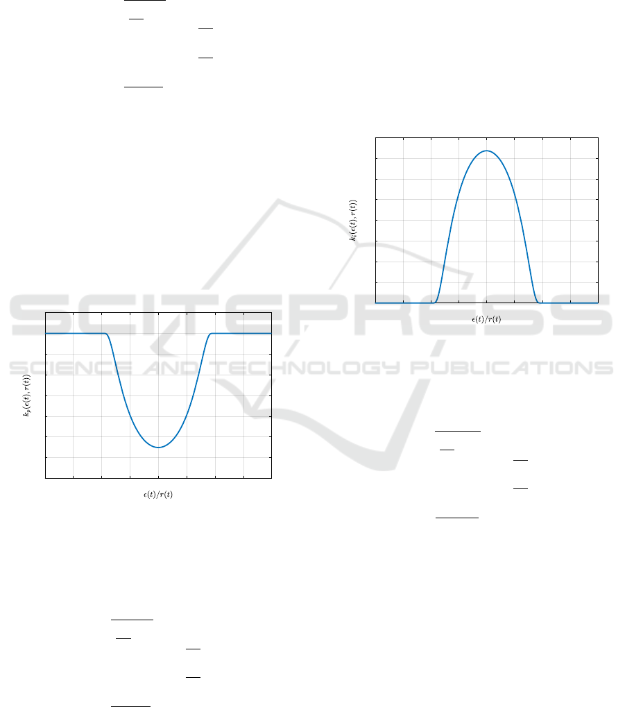
range. Figure 1 below shows an example of a propor-
tional gain k
p
that is constructed by this function and
tuned for certain values of a, k
0
and r(t).
-2 -1.5 -1 -0.5 0 0.5 1 1.5 2
0.8
0.9
1
1.1
1.2
1.3
1.4
1.5
1.6
Figure 1: The proposed nonlinear function derivative gain
for a constant set-point r(t) = 1 and tuning parameters
k
0
= 1.5, a = 1.
The nonlinear integral gain is described by:
k
i
(ε(t), r(t)) =
k
1
e
1
ε(t)
r(t)
2
− 1
if
ε(t)
r(t)
< 1, r(t) ̸= 0
0 if
ε(t)
r(t)
≥ 1, r(t) ̸= 0
k
1
e
1
|ε(t)|
2
− 1
if |ε(t)| < 1, r(t) = 0
0 if |ε(t)| ≥ 1, r(t) = 0
(5)
where k
1
is the integral constant that determines
the largest value of the integral nonlinear gain. In
this case, the set-point function r(t) also affects the
gain where it enlarges and shrinks the integral non-
linearity in order to adapt to the error range, so that
the non-linearity is active throughout the transient re-
sponse.
The integral gain, shown in Figure 2, is built
according to Eq. (5) and it is designed so that it
starts from a value of zero and increases as the er-
ror approaches steady-state, approaching its maximal
bounded value. This allows for the integral to error-
correct the system during steady state while keep-
ing a low integral value during the transient response,
which helps maintain low overshoot.
-2 -1.5 -1 -0.5 0 0.5 1 1.5 2
0
0.05
0.1
0.15
0.2
0.25
0.3
0.35
0.4
Figure 2: The proposed nonlinear function integral gain for
a constant set-point r(t) = 1 and tuning parameters k
1
= 1.
The nonlinear derivative gain is described by:
k
d
(
˙
ε(t), r(t)) =
k
2
e
1
˙
ε(t)
r(t)
2
− k
2
3
if
˙
ε(t)
r(t)
< k
3
, r(t) ̸= 0
0 if
˙
ε(t)
r(t)
≥ k
3
, r(t) ̸= 0
k
2
e
1
|
˙
ε(t)|
2
− k
2
3
if |
˙
ε(t)| < k
3
, r(t) = 0
0 if |
˙
ε(t)| ≥ k
3
, r(t) = 0
(6)
where k
2
is the derivative constant that increases the
maximum derivative value, r(t) is the set-point func-
tion which can enlarge and shrink the nonlinearity ac-
cordingly in a similar behaviour to the previous non-
linear gains. For the derivative gain, as it can be
noticed, the input to the nonlinear derivative func-
tion is the error rate instead of the error. This helps
the controller to easily identify the point of steady-
state, where the derivative gain is maximized for in-
creased damping, minimizing overshoot, while be-
coming zero at error rate values higher than the filter
constant k
3
.
Towards a Novel Nonlinear PID Controller Tuned with Particle Swarm Optimization with Improved Performance for First Order Plus Time
Delay (FOPTD) Systems
27
The constant k
3
is the filtering constant which is
a design value determined by the designer according
to the amount of derivative needed to be included in
the controller. This constant is useful to overcome
some of the well-known PID limitations. It reduces
the derivative kick and reduces the impact of high-
frequency noise that might affect the system input.
It changes the range at which the nonlinearity oper-
ates and defines the zero points of the nonlinear gains.
This means that the control designer has the ability to
freely adjust the noise signals that one wants to elim-
inate.
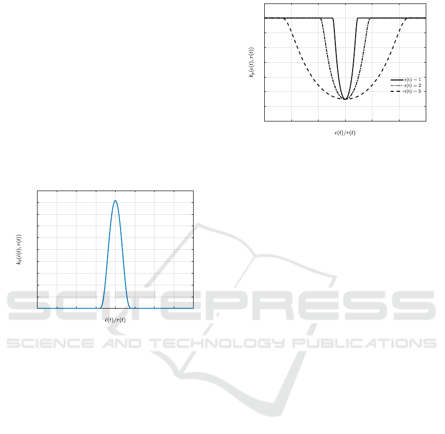
An example of tuned derivative gain is shown in
Figure 3. It has similar shape to the integral gain,
where the difference between the two gains is con-
trolled by the design filtering constant k
3
.
-2 -1.5 -1 -0.5 0 0.5 1 1.5 2
0
0.002
0.004
0.006
0.008
0.01
0.012
0.014
0.016
0.018
0.02
Figure 3: The proposed nonlinear function derivative gain
for a constant set-point r(t) = 1 and tuning parameters
k
2
= 1, k
3
= 0.5.
The effect of a changing set-point to the proposed
nonlinear proportional gain is shown in Figure 4
where the larger the set-point becomes, the wider the
nonlinearities are, preserving the design constants,
such as the maximum value of the gains, the minimum
value of the gains, and so that the nonlinearities are
active within the range −ε
max
≤ ε ≤ ε
max
. Similar im-
pact also occurs on the integral and derivative gains as
discussed above. Having r(t) in the definition of the
three gains makes them all work in synchronization
according to the reference function in order to maxi-
mize the speed during the transient response and max-
imise robustness during the steady-state. This will
improve disturbance rejection and will accommodate
any unmodeled uncertainties as it will be shown.
3 TUNING METHODOLOGY
PID control research has the difficulty and unfortu-
nate disadvantage that many control comparisons are
-6 -4 -2 0 2 4 6
0.8
0.9
1
1.1
1.2
1.3
1.4
1.5
1.6
Figure 4: The adaptation of the proposed nonlinear function
proportional gain to changing set-point values r(t) = 1, 2,
and 5.
unfair and improved results can be achieved by spend-
ing more effort on tuning (
˚
Astr
¨
om and H
¨
agglund,
1995; Valluru and Singh, 2018; Chen et al., 2019;
Joseph et al., 2022). The control criteria that are
considered in this paper for judging the control per-
formance include both fast set-point tracking with no
overshoot and robustness against disturbance and un-
certainties, which is the scope of improving upon the
PID limitations. The difficulty being when a fair com-
parison is needed it must be ensured that the right tun-
ing approach is taken and is made transparent.
The Particle Swarm Optimization (PSO) algo-
rithm is a stochastic optimization algorithm that is
simple, effective, and able to find optimal values to
optimization problems, without the use of derivatives
(Shaikh and Yadav, 2022). Due to these features of
PSO, it is frequently used with high success in the
tuning of nonlinear PID control problems (Shaikh and
Yadav, 2022; Joseph et al., 2022). As a result, it is
used to tune the proposed NLPID controller and a lin-
ear PID controller for the process of benchmarking
for the case of an FOPTD system.
The tuning of the proposed NLPID parameters
k
0
, k
1
, k
2
, and a are conducted using the objective
function and optimization problem designed with the
Integral Time Absolute Error (ITAE) performance
measure and the settling time of the system as:
minimize
k
0
, k
1
, k
2
, a
f (t, ε(t),t
s
) =
Z
t
f
0
t|ε(t)|dt + t
s
subject to 0 ≤k
0
, k
1
, k
2
≤ 3,
0 ≤a,
a ≤ 3
(7)
where t
s
is the settling time, ε(t) is the feedback error,
t
f
is the final time. The optimization problem is de-
fined with the parameter constraints within the speci-
fied region to ensure stability and lower the chances of
ICINCO 2023 - 20th International Conference on Informatics in Control, Automation and Robotics
28

trapping inside local optima. The objective function
minimises the feedback error as fast as possible, meet-
ing the requirements of minimising overshoot and rise
time. The settling time is added to the objective func-
tion to enhance the speed of the response for the fast
elimination of the steady-state error, improving the
transient response as per the proposed specifications.
The parameter k
3
is a filtering parameter determined
by the designer without the necessity of a tuning al-
gorithm. For the case of FOPTD systems, PI control
can provide excellent response and derivative action
is not necessary. As a result, the filtering parameter
k
3
= 0.5 is designed and justified for the control of
FOPTD systems. The PSO algorithm iterates until the
final iteration has been reached, using the following
steps (Wang et al., 2018; Shaikh and Yadav, 2022):
1. Generate n number of random position particle
vector X
n
0
in the range [k
min
, k
max
] for k
0
, k
1
, k
2
and
[a
min
, a
max
] for a.
2. Assume initial velocity vector V
n
0
= 0.
3. Simulate the control system in Simulink.
4. Compute f (t, ε(t), t
s
) =
R
t
f
0
t|ε(t)|dt + t
s
.
5. If values surpass the defined range, re-initialise a
random number in range [k
min
, k
max
] for k
0
, k
1
, k
2
and re-initialise a random number in range
[a
min
, a
max
] for a.
6. The new velocity and position of each particle is
computed using a slightly modified version of the
PSO algorithm as:
k
V
j
i+1
= |
k
V
j
i
+
k
r
j
i
c
1
(
k
Gbest
i
−
k
P
j
i
)| (8)
k
X
j
i+1
= |
k
X
j
i
+
k
V
j
i+1
| (9)
7. Re-iterate.
where
k
V
j
i
is the velocity vector for each iteration i,
particle j, and tuning parameter k,
k
X
j
i
is the position
vector for each iteration i, particle j, and tuning pa-
rameter k,
k
r
j
i
is the stochastic variable that changes
for every iteration and lies in the range [0,1], Gbest
is the minimum value of the objective function of all
particles across iterations, each particle representing
a specific tuning parameter set P
j
i
[k
0
, k
1
, k
2
, a]
j
i
. The
variable k represents a natural number taking values 1
to 4, iterating between the 4 parameters in the param-
eter set. If the new position X
j
i+1
is outside the speci-
fied range of values, then these specific new particles
are re-initialized within the pre-specified range. The
parameter c
1
= 1.3 is a tuning parameter taken from
research surveys on PSO tuning (Wang et al., 2018).
This process is a modification of the original par-
ticle swarm optimization, which included the history
of the minimum objective value for each particle, in
this case only the social best values are considered.
The modified PSO algorithm searched for the non-
linear gain parameters k
0
, k
1
, k
2
, and a that minimize
settling time, overshoot, and transient response as per
the design constraints.
4 SIMULATION EXAMPLE
The proposed NLPID controller is benchmarked
against the conventional and state-of-the-art methods
of controlling FOPTD system, represented as follows:
P(s) =
e
−0.5s
s + 1
; (10)
The FOPTD process model is to be controlled un-
der the following control criteria:
• Minimization of overshoot ≤ 2%.
• Minimization of rise time and settling time.
• Fast Disturbance rejection to input and output dis-
turbances.
Using these control criteria, all controllers have
been tuned appropriately and are then benchmarked
against the proposed NLPID controller.
To create a comparison between the different
methods, the proposed NLPID controller is bench-
marked against conventional and nonlinear control
methods. The proposed NLPID controller is bench-
marked on the basis of the claim that it is providing
an improvement to the fast set-point tracking and dis-
turbance rejection. The system is simulated and com-
pared against conventional and nonlinear controllers
in the FOPTD system in both set-point tracking and
in disturbance rejection.
NLPID
P(s)
+
Set-Point
r(t)
ε(t)
+
d
1
+
d
2
Measurement
−
Figure 5: The schematic block diagram of the control sys-
tem with both the input and output disturbances.
A linear PID controller with derivative filtering
has been tuned using the PSO optimisation algorithm.
The format of the linear PID controller follows the
MATLAB filtered PID controller parallel form as fol-
lows:
K
PID
(s) = k
p
+ k
i
1
s
+
k
d
N
1 −
N
s
(11)
Towards a Novel Nonlinear PID Controller Tuned with Particle Swarm Optimization with Improved Performance for First Order Plus Time
Delay (FOPTD) Systems
29
The Son NLPID controller has a nonlinearity in
the integral gain of the PID controller while the pro-
portional and derivative gains are constants. The
Son NLPID controller takes the following form (Son
et al., 2021):
u(t) = k
p
ε(t) + k
i
Z
e
−
ε(t)
2∆r(t)
2
ε(t)dt + k
d
dε(t)
dt
(12)
where ∆r(t) is the set-point change and follows the
condition that ∆r(t) ̸= 0.
The PSO algorithm determines the NLPID and
PSO PID gains shown in Table 1. The tuning for the
Son NLPID and IMC PID controllers are from liter-
ature for the equivalent FOPTD system shown in Ta-
ble 1 (Son et al., 2021).
Table 1: Tuned values of the control parameters for each
controller.
Tuning Parameters
Proposed k
0
= 1.54, k
1
= 2.95, k
2
= 2.32, k
3
=
0.50, a = 1.13
IMC PID k
p
= 1.11, k
i
= 0.88, k
d
= 0.11
PSO PID k
p
= 0.77, k
i
= 1.13, k
d
= 0.74, N =
0.44
Son NLPID k
p
= 1.98, k
i
= 1.94, k
d
= 0.36
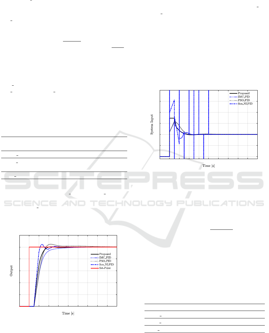
Figure 6 illustrates that the proposed NLPID con-
troller outperforms the IMC PID and PSO PID con-
trollers, showing faster rise and settling time. Al-
though the Son NLPID controller indicates faster rise
time, it also presents an overshoot of approximately
4.8%, while the proposed NLPID controller shows an
overshoot of 0.35%.
0 1 2 3 4 5 6 7 8 9 10
0
0.2
0.4
0.6
0.8
1
1.2
Figure 6: Benchmarking controllers to a step set-point func-
tion response.
Figure 7 shows the system input of each bench-
marked control system. The proposed NLPID con-
troller indicates the cheapest control strategy with
practical and effective system input that does not
generate large derivative and proportional kick sig-
nals. It is clear from the figure that the IMC PID
and Son NLPID controllers show large derivative and
proportional kicks, making them energy expensive
control strategies. This also indicates the internal sta-
bility of the proposed NLPID controller under step
set-point tracking. The derivative kicks are presented
in the input during benchmarking and the authors of
the paper have been contacted to inquire about how
they dealt with the derivative kicks, but no response
has been received. In order to reproduce the most
accurate form of the controllers, the derivative kicks
have not been filtered.
0 1 2 3 4 5 6 7 8 9 10
0
0.5
1
1.5
2
2.5
3
Figure 7: System input due to step set-point function re-
sponse.
Table 2 shows the control criteria of a step set-
point response of all the controllers. The L
2
energy
has also been computed to show the system input en-
ergy generated by each controller. The L
2
computa-
tion has the following form:
L
2
(u(t)) =
v
u
u
t
t
f
∑
t
0
(u(t)
2
) (13)
It is clearly shown that the proposed NLPID con-
troller produces the fastest response with minimal
overshoot and lowest system input energy.
Table 2: The benchmark results of the set-point response
control criteria.
%Os t
s
(s) t
r
(s) L
2
Proposed 0.35 2.76 0.82 43.94
IMC PID 0 4.26 1.16 1.55 × 10
13
PSO PID 4.48 3.98 0.88 44.34
Son NLPID 4.8 3.15 0.45 5.11 × 10
13
For the benchmark testing, the disturbance rejec-
tion has been taken to be 10% of the set-point value,
applied to the system input at 6 seconds time mark
and a 10% disturbance has also been taken in the out-
put at 12 seconds time mark, which represents a sen-
ICINCO 2023 - 20th International Conference on Informatics in Control, Automation and Robotics
30
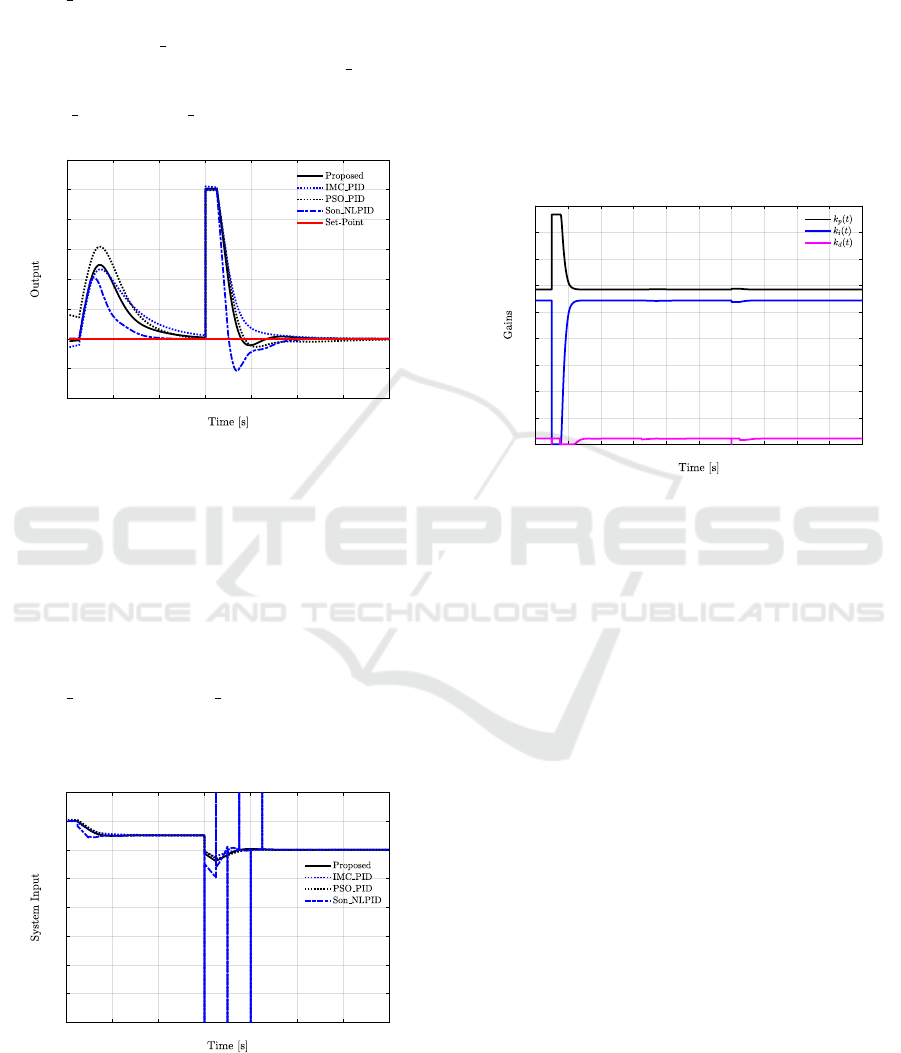
sor bias and deviation from the true value as shown
by Figure 5. The proposed NLPID controller has the
fastest output disturbance rejection response, while
the Son NLPID controller has the fastest input dis-
turbance rejection response. The proposed NLPID
controller and IMC PID show a faster response with
no overshoot when compared to the PSO PID con-
troller. The proposed NLPID controller outperforms
the IMC PID and PSO PID in both input and output
disturbance rejections.
6 8 10 12 14 16 18 20
0.96
0.98
1
1.02
1.04
1.06
1.08
1.1
1.12
Figure 8: Output response of both input and output distur-
bances.
The input and output disturbance rejection of con-
trol systems can at times render a system internally
unstable. As a result, the system input energy has
been shown in order to show internal stability and
practicality of the controllers. It is clearly shown
from Figure 9 that the proposed NLPID controller
and all benchmarked controllers are internally sta-
ble with bounded system input signals. However,
the Son NLPID and IMC PID controllers indicated
derivative kick signals due to the step function distur-
bances, which also have a negative effect on system
input energy.
6 8 10 12 14 16 18 20
-0.4
-0.2
0
0.2
0.4
0.6
0.8
1
1.2
Figure 9: System input due to the disturbance rejection re-
sponse in both input and output disturbances.
Figure 10 shows the time variation of the nonlin-
ear function gains. The initial value of the set-point
is zero, as a result, the functions take the steady-
state value and as the set-point is produced the func-
tions then increase and settle again as the system ap-
proaches steady-state value. The nonlinear propor-
tional gain produces a large signal with a fast response
initially, which then reduces rapidly near steady state
to reduce the overshoot. The nonlinear integral gain
increases as steady state error approaches to eliminate
any steady state error. It can also be seen that when
the step function is applied in both set-point and dis-
turbances, the derivative gain rapidly reduces to zero,
eliminating any unwanted derivative kick effects.
0 2 4 6 8 10 12 14 16 18 20
0
0.2
0.4
0.6
0.8
1
1.2
1.4
1.6
1.8
Figure 10: The time variation of the proposed nonlinear
gains to the step response and disturbance rejection.
The effectiveness of the proposed NLPID con-
troller comes from the properties of the proposed non-
linear gain functions. The nonlinear proportional gain
produces a large signal at large errors, quickly re-
ducing the feedback error, then rapidly decreasing to
avoid overcompensation. The nonlinear integral gain
is negligible at large errors and increases rapidly near
steady-state for the purpose of eliminating left-over
steady-state errors. Finally, the derivative gain is pro-
duced near steady-state in order to minimise over-
shoot and oscillatory responses. These properties of
the proposed NLPID controller provide the fast tran-
sient response with minimal overshoot, while main-
taining fast disturbance rejection.
5 ROBUSTNESS OF PROPOSED
NLPID CONTROLLER
AGAINST PARAMETRIC
UNCERTAINTY
Nonlinear controllers introduce additional nonlinear-
ity into the system, and as a result robustness tests of
the proposed controller must be conducted. Robust-
ness tests are used to show that the proposed NLPID
Towards a Novel Nonlinear PID Controller Tuned with Particle Swarm Optimization with Improved Performance for First Order Plus Time
Delay (FOPTD) Systems
31

controller has the properties of robust stability and
performance, in varying plant dynamics, in the case
of inaccurate FOPTD models. The parametric uncer-
tainty of the nominal FOPTD plant is modelled using
Eq. (14) in the following transfer function format:
P(s) =
ke
τs
t
p
s + 1
(14)
where 0.9 ≤ k ≤ 1.1, 0.9 ≤ t
p
≤ 1.1, and 0.45 ≤ τ ≤
0.55, which models a ±10% variable change.
Figure 11 shows how the proposed NLPID con-
troller responds to ±10% variations in gain k, lag t
p
,
and delay parameter τ. It can be seen that there are no
large variations of overshoot and no instabilities. In
the case where the gain and lag parameters are under-
estimated, the response shows a small overshoot and
a larger settling time. The system shows no effect on
stability, providing evidence for robust performance
and robust stability of the proposed NLPID to gain,
lag, and delay variations.
0 1 2 3 4 5 6 7 8 9 10
0
0.2
0.4
0.6
0.8
1
1.2
Figure 11: Output response to step set-point function under
parametric uncertainty.
Figure 12 shows the system input of the proposed
NLPID controller under parametric uncertainty. This
indicates that the proposed NLPID controller gen-
erates minimal to none derivative and proportional
kicks, making it an effective and practical controller.
In addition it indicates that the proposed controller
has no hidden internal instabilities produced due to
parametric uncertainty, hence indicating that the pro-
posed NLPID controller is an effective and robust
control method.
According to the parametric uncertainty study,
it can be seen that the proposed NLPID controller
shows resilience to parameter variations in a struc-
tured model uncertainty, showing robust stability. The
uncertainty tests indicate that stability is maintained
across different types of parameter variations with
some changes in performance of approximately 3 sec-
onds slower settling time, when compared to the nom-
0 1 2 3 4 5 6 7 8 9 10
0
0.2
0.4
0.6
0.8
1
1.2
1.4
1.6
1.8
Figure 12: System input due to parametric uncertainty.
inal plant, and approximately 10% maximum over-
shoot.
6 CONCLUSIONS
The tuning of the proposed NLPID controller is con-
ducted using the PSO algorithm to find the optimal
values. This is then simulated and compared against
IMC PID, PSO PID, and Son NLPID for a FOPTD
system.
The proposed NLPID controller outperforms the
conventional control systems in simultaneous tran-
sient response and disturbance rejection, which is
a critical response specification in control systems.
The proposed NLPID controller also outperforms
the Son NLPID controller in set-point tracking re-
sponse and output disturbance rejection. However,
the Son NLPID controller outperforms the proposed
NLPID controller in input disturbance rejection. The
proposed controller also shows robust stability and ro-
bust performance to parametric uncertainty with no
large variations.
As part of future work, the authors will work on
applying the proposed NLPID controller to different
plants with nonlinearities and non-minimum phase
characteristics. The authors will also work on a novel
controller that will contain the proposed NLPID con-
trol structure with an extended state observer, with the
effect of improving robustness, disturbance rejection,
and transient response characteristics.
REFERENCES
˚
Astr
¨
om, K. J. and H
¨
agglund, T. (1995). PID Controllers:
Theory, Design and Tuning. Instrument Society of
America, 2nd edition.
Bernstein, D. S. (2022). Facing Future Challenges in Feed-
back Control of Aerospace Systems Through Scien-
ICINCO 2023 - 20th International Conference on Informatics in Control, Automation and Robotics
32

tific Experimentation. Journal of Guidance, Control,
and Dynamics, 45(12):2202–2210.
Cetin, M. and Iplikci, S. (2015). A novel auto-tuning PID
control mechanism for nonlinear systems. ISA Trans-
actions, 58:292–308.
Chen, J., Fang, S., and Ishii, H. (2019). Fundamental lim-
itations and intrinsic limits of feedback: An overview
in an information age. Annual Reviews in Control,
47:155–177.
Garpinger, O., H
¨
agglund, T., and
˚
Astr
¨
om, K. J. (2014).
Performance and robustness trade-offs in PID control.
Journal of Process Control, 24(5):568–577.
Jin, G.-G. and Son, Y.-D. (2019). Design of a Nonlinear PID
Controller and Tuning Rules for First-Order Plus Time
Delay Models. STUD INFORM CONTROL, 28(2).
Joseph, S. B., Dada, E. G., Abidemi, A., Oyewola, D. O.,
and Khammas, B. M. (2022). Metaheuristic algo-
rithms for PID controller parameters tuning: Review,
approaches and open problems. Heliyon, 8(5):e09399.
O’Dwyer, A. (2009). Handbook of PI and PID Controller
Tuning Rules. Imperial College Press ; Distributed by
World Scientific Pub, London : Hackensack, NJ, 3rd
ed edition.
Pathak, D., Bhati, S., and Gaur, P. (2020). Fractional-order
nonlinear PID controller based maximum power ex-
traction method for a direct-driven wind energy sys-
tem. International Transactions on Electrical Energy
Systems, 30(12):e12641.
Pugazhenthi P, N., Selvaperumal, S., and Vijayakumar, K.
(2021). Nonlinear PID controller parameter optimiza-
tion using modified hybrid artificial bee colony al-
gorithm for continuous stirred tank reactor. Polska
Akademia Nauk. Bulletin of the Polish Academy of
Sciences: Technical Sciences, 69(3).
Shaikh, M. and Yadav, D. (2022). A Review of Particle
Swarm Optimization ( PSO) Algorithm.
Shamseldin, M. A. (2023). Design of Auto-Tuning Nonlin-
ear PID Tracking Speed Control for Electric Vehicle
with Uncertainty Consideration. World Electric Vehi-
cle Journal, 14(4):78.
Sivadasan, J., Iruthayarajan, M. W., Stonier, A. A., and Ray-
mon, A. (2023). Design of Cross-Coupled Nonlinear
PID Controller Using Single-Objective Evolutionary
Algorithms. Mathematical Problems in Engineering,
2023:e7820047.
So, G.-B. (2019). EA-Based Design of a Nonlinear PID
Controller Using an Error Scaling Technique. SIC,
28(3):279–288.
Son, Y.-D., Bin, S.-D., and Jin, G.-G. (2021). Stability
Analysis of a Nonlinear PID Controller. Int. J. Control
Autom. Syst., 19(10):3400–3408.
Valluru, S. K. and Singh, M. (2018). Performance in-
vestigations of APSO tuned linear and nonlinear PID
controllers for a nonlinear dynamical system. Jour-
nal of Electrical Systems and Information Technology,
5(3):442–452.
Wang, D., Tan, D., and Liu, L. (2018). Particle swarm
optimization algorithm: An overview. Soft Comput,
22(2):387–408.
Towards a Novel Nonlinear PID Controller Tuned with Particle Swarm Optimization with Improved Performance for First Order Plus Time
Delay (FOPTD) Systems
33
