
Sensorless Reduction of Cane Oscillations Aimed at Improving Robotic
Grapevine Winter Pruning
Andrea Fimiani
1 a
, Pierluigi Arpenti
1 b
, Matteo Gatti
2 c
and Fabio Ruggiero
1 d
1
Dip. di Ingeg. Elet. e Tecn. dell’Inform., Universit
`
a degli Studi di Napoli Federico II, Via Claudio 21, Napoli, Italy
2
Dipartimento di Scienze delle Produzioni Vegetali Sostenibili, Universit
`
a Cattolica del Sacro Cuore, Piacenza, Italy
fi
Keywords:
Agricultural Automation, Robotic Pruning, Momentum-Based Observer.
Abstract:
Agricultural sector faces challenges like high labour costs and a shortage of qualified workers for repetitive
tasks, leading to increased interest in agricultural robotics. Pruning is a focus for automation efforts worldwide.
However, pruning robots struggle with slow and inaccurate vision systems, resulting in slow, costly, and
potentially harmful operations for plants. This study aims to provide a reproducible and reliable method for
detecting contact with grapevines during pruning, minimising potential damage, and improving vision system
speed by reducing cane oscillations. The proposed approach uses a momentum-based observer, eliminating
the need for force sensors. Experiments on Vitis vinifera cv. Pinot Noir canes validated this methodology.
1 INTRODUCTION
Grapevine winter pruning is an essential practice that
must be performed annually over dormancy. From a
viticulture perspective, it holds great significance as
it profoundly impacts various aspects of vine growth,
yield, and fruit quality (Poni et al., 2018). Pruning
grapevines differs from pruning other fruit trees for
several reasons encompassing distinctive plant mor-
phology, bud fruitfulness, and training systems. In-
deed, it involves making specific cuts on dormant
grapevines aimed at removing part of the previous
season’s growth as well as retaining selected dormant
shoots, namely, canes and spurs (Poni et al., 2016).
Pruning requires the pruner’s ability to quickly recog-
nise and locate cutting points in narrow spaces despite
cane density and other trellis accessories that may ob-
struct vision (Guadagna et al., 2023). Due to the in-
trinsic complexity of the task, robotising grapevine
winter pruning requires a multidisciplinary approach
to address challenges ranging from cutting point iden-
tification to path planning in a cluttered environment
and cane collision detection (Epee et al., 2022). Cam-
eras often have lengthy processing times and may
provide inaccurate position estimates, causing ineffi-
a
https://orcid.org/0009-0006-4452-0106
b
https://orcid.org/0000-0002-0327-3069
c
https://orcid.org/0000-0003-4195-7709
d
https://orcid.org/0000-0001-7539-9157
ciencies in pruning tasks and the risk of plant dam-
age. This limitation remains a significant hurdle in
robotics, especially for pruning (Zahid et al., 2021).
While improving position estimation algorithms can
enhance accuracy, it is not always feasible due to at-
mospheric conditions and obstructed camera views.
Another challenge arises from pruning-induced os-
cillations caused by manipulator-cane collisions and
cutting. These oscillations worsen when the manipu-
lator applies unnecessary force to the cane, resulting
from inaccurate node position estimation. This ex-
cess force can bend the vine due to its rigid support
and elastic cane material. After trimming, the plant
starts oscillating, potentially damaging it and slowing
down the vision system, impacting productivity. The
oscillation issue is addressed by rapidly detecting col-
lisions between the shear centre and the trim point,
preventing the robot from unnecessary vine pushing.
Collision detection strategies can adapt to context and
application, but traditional methods involve expensive
force sensors and robot’s end-effector modifications.
Building upon these developments, this paper aims to
reduce cane oscillations induced by the collisions oc-
curring during pruning, relying on measures retrieved
from proprioceptive sensors only.
This paper introduces a novel approach, lever-
aging a momentum-based observer (De Luca et al.,
2006) for collision detection in precision viticulture,
specifically in grapevine winter pruning. To the best
of our knowledge, this is the first application of the
640
Fimiani, A., Arpenti, P., Gatti, M. and Ruggiero, F.
Sensorless Reduction of Cane Oscillations Aimed at Improving Robotic Grapevine Winter Pruning.
DOI: 10.5220/0012182500003543
In Proceedings of the 20th International Conference on Informatics in Control, Automation and Robotics (ICINCO 2023) - Volume 1, pages 640-647
ISBN: 978-989-758-670-5; ISSN: 2184-2809
Copyright © 2023 by SCITEPRESS – Science and Technology Publications, Lda. Under CC license (CC BY-NC-ND 4.0)
momentum-based observer in this context, address-
ing collisions occurring before and after the expected
cutting point. This work focuses on the former to
minimize cane pushing and oscillations. The latter
is crucial to avoid false cuts that could slow down the
pruning process, and it is not deepened in this work.
Additionally, the paper enhances system repro-
ducibility and reliability by proposing an affordable,
customised electromechanical setup compatible with
off-the-shelf commercial shears, eliminating the need
for specialised equipment.
The paper’s outline is: Section 2 revises the avail-
able solutions for robot pruning; Section 3 presents
the collision management framework; an extensive
experimental campaign is proposed in Section 4,
showing that the momentum-based observer prevents
the manipulator from damaging the vine and inducing
low amplitude oscillations; conclusions are supported
by the statistical analysis presented in Section 4.4,
based on the metrics described in Section 4.3; Sec-
tion 5 concludes the paper.
2 LITERATURE REVIEW
A comprehensive perception system is often re-
quired to understand the plant’s structure and make
informed-cutting decisions. A vision system that re-
constructs the tree canopy in 3D, identifies retained
canes and pruning decisions, calculates pruning point
coordinates, and plans collision-free paths, has been
proposed for cane pruning (Botterill et al., 2017). On
the other hand, some robotic systems incorporate vi-
sion sensors mounted on the manipulator’s arm. For
instance, an approach that utilises an RGB-D cam-
era and custom pneumatic shears as the cutting tool
has been developed (You et al., 2020). Recently, a
deep learning-based methodology for pruning region
detection and canopy segmentation of mature spur-
pruned grapevines has been proposed (Guadagna
et al., 2023). A multi-modular framework that com-
bines deep learning, computer vision, and robot con-
trol for dynamic and reproducible pruning skills has
been proposed (Katyara et al., 2020). A notable
example of a robot involved in grapevine pruning
is the Rolling Panda (Teng et al., 2021). It is a
wheeled mobile manipulator system consisting of a
non-holonomic wheeled mobile platform and a seven
degrees-of-freedom (DoF) robotic arm, incorporat-
ing a hierarchical control strategy that prioritises the
desired path while considering other constraints us-
ing the stack-of-tasks framework. While initially de-
signed to enhance safety in human-robot interaction
scenarios, the momentum-based observer employed
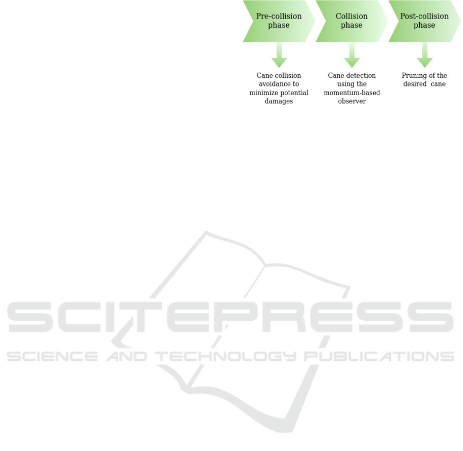
Figure 1: Collision management diagram.
in this paper has been successfully adapted to diverse
robotic systems and situations. For instance, in the
field of legged robots, it has been used to estimate ex-
ternal disturbances acting on the legs of a quadrupedal
robot (Morlando et al., 2021) or to accurately lo-
calise external contacts on an Atlas robot using a
contact particle filter (Manuelli and Tedrake, 2016).
In aerial robotics, the momentum-based observer has
been employed on fully actuated aerial robots to es-
timate external contact forces during physically inter-
active aerial tasks (Ryll et al., 2017). Notably, it has
been further enhanced by using a higher-order esti-
mator for estimating external wrenches in the decen-
tralised control of aerial robotic manipulators (Rug-
giero et al., 2015).
3 COLLISIONS MANAGEMENT
Collision management techniques developed for
robot-human collisions can also be applied to manage
robot-cane collisions. Collision events can be divided
into three main phases, namely pre-collision phase,
collision phase, and post-collision phase, as synthet-
ically depicted in Fig. 1. The pre-collision phase re-
gards the design of an appropriate path planning al-
gorithm to quickly generate the trajectory as the en-
vironment changes with each cut, based on the ex-
tensive use of exteroceptive sensors, such as cameras
or range sensors. These arguments, briefly revised in
Section 2, are out of the scope of the presented work
and, thus, will not be further deepened.
The collision phase is the second phase of the
collision handling process, and its primary goal is
to rapidly detect the occurrence of the collision be-
tween the shears mounted on the manipulator’s end-
effector and the cane while gathering as much in-
formation as possible from the impact forces. It
is important to note that the collision phase can be
complex and requires careful design and implemen-
tation. Particular attention should be given to the ac-
curacy and timeliness of collision detection, as well
as the robustness of the system in avoiding false pos-
Sensorless Reduction of Cane Oscillations Aimed at Improving Robotic Grapevine Winter Pruning
641

itives. This paper proposes to manage the collision
between the shear and the vine using an n
th
-order
momentum-based observer. The momentum-based
observer (De Luca et al., 2006) is a reliable collision
detection method to enhance safety in human-robot
interaction scenarios. The approach based on the gen-
eralised momentum is widely used since it avoids the
calculation of acceleration that introduces noise and
delay. Indeed, this method relies on the available
model knowledge, the last commanded torques, and
the signals retrieved from proprioceptive position sen-
sors to estimate the lumped effect of all unmodelled
terms (interaction with the environment, disturbances,
effects from model uncertainties, etc.) as joint torque
τ
e
. Considering a rigid-link manipulator with n > 0
joints, the dynamic model of n-DoF robot manipula-
tors is presented as follows
M(q) ¨q +C(q, ˙q) ˙q + g(q) = τ
tot
,
(1)
where the matrices M(q) ≻0 ∈R
n×n
, C(q, ˙q) ∈R
n×n
,
and g(q) ∈ R
n
represent the inertia matrix, Coriolis
and centrifugal terms matrix, and gravity vector, re-
spectively. The symbol ≻ 0 indicates that the related
matrix is positive-definite. Vectors q, ˙q, ¨q ∈ R
n
repre-
sent the joint angular position, velocity, and accelera-
tion, respectively, while τ
tot
∈ R
n
represents the total
torque acting on each joint actuator. This total torque
can be divided into two components, namely τ ∈ R
n
,
which represents the input torques commanded to the
joint actuators and τ
e
∈ R
n
, which represents the ex-
ternal joint torque acting on them. Define the gener-
alised momentum of the system as p = M(q) ˙q ∈ R
n
.
Because of the skew-symmetry property of the iner-
tia matrix, namely
˙
M(q) = C(q, ˙q)+C
T
(q, ˙q), the fol-
lowing
˙p = τ
tot
+C
T
(q, ˙q) ˙q −g(q)
(2)
holds. The derivation of the classic first-order mo-
mentum observer is based on the following defini-
tion of the collision detection signal r(t) = K
I
h
p(t) −
R
t
0
(τ + C
T
(q, ˙q) ˙q −g(q) + r) ds − p(0)
i
, where p(0)
is the value of the momentum at time t = 0 s, and
K
I
≻ 0 ∈ R
n×n
is a diagonal gain matrix. Using (2)
and the dynamic model in (1), the following expres-
sion is derived
˙r = −K
I
r + K
I
τ
e
.
(3)
When a collision occurs, the signal r exhibits expo-
nential growth and collision detection can be achieved
by comparing it to a threshold value r
low
determined
based on the system’s noise characteristics. In ideal
conditions, as the gain K
I
tends to infinity, the signal
r closely approximates the external torques acting on
the manipulator τ
e
. Therefore, higher gains are prefer-
able to enhance the sensitivity of collision detection.
Due to its properties, the signal r can infer the exter-
nal forces f
ext
exerted on the end effector of the ma-
nipulator. Indicating with † the left pseudo-inverse
of a given matrix, it is possible to write r ≊ τ
e
=
J
T
F
ext
⇒ f
ext
= (J
T
)
†
r. The dynamics of the collision
identification signal in (3) can be studied component-
wise in the Laplace domain as
r
j
(s)
τ
e, j
(s)
=
K
I, j
s + K
I, j
with
j = 1, . . . , n. These transfer functions represent first-
order systems with a negative real-part pole at −K
I, j
.
The negative pole ensures the collision identification
signal r
j
convergence towards τ
e, j
at steady-state. To
achieve a more accurate and precise collision detec-
tion response and to mitigate the impact of high-
frequency noise, a second-order observer can be de-
signed by assuming a linear relationship between ex-
ternal forces and their estimation in the Laplace do-
main. This can be achieved by employing a second-
order transfer function as T
i
(s) =
ω
2
n,i
s
2
+ 2ζ
i
ω
n,i
s + ω
2
n,i
with i = 1, . . . , n, where ω
2
n,i
and ζ
i
are the desired
natural frequency and damping of the designed esti-
mator, respectively. To achieve the desired transfer
function, the collision identification signal can be ex-
pressed in the time domain as r(t) = K
1
R
t
0
−r(s) +
K
2
h
q(s) −
R
t
0
(τ +C
T
(q, ˙q) ˙q −g(q) + r)ds − p(0)
i
ds,
where it is assumed that q(0) = r(0) = ˙r(0) = 0, while
K
1
≻ 0 ∈ R
n×n
and K
2
≻ 0 ∈ R
n×n
are diagonal ma-
trices. Generalising the above reasoning, it is possi-
ble to extend the discussion to an n
th
-order estima-
tor, which is described by the following detection sig-
nal (Morlando et al., 2021) γ
i
(t) = K
i
R
t
0
−r + γ
i−1
ds,
with i = 2, . . . , n, and where
∏
n
i= j+1
K
i
= c
j
with j =
0, . . . , n −1 and c
j
represents the coefficients in the
denominator of the desired transfer function.
For the specific task of this paper, the detection of
a collision serves as a triggering signal to start prun-
ing. The cutting process has to fulfil specific prede-
termined requirements.
• Reduction of Cane Deflection. During pruning,
it is crucial not to compromise the integrity of the
vine cane.
• Fast Trim Point Recognition. Cutting each trim
point has to be performed in such a way as to
speed up the overall pruning process.
• Cost-Effective Solution. The robotic system
must be easily adaptable to any pruning require-
ment and must increase production.
To meet the above functional requirements, it is nec-
essary to establish appropriate metrics that capture the
cutting process’s effects on vine dynamics.
ICINCO 2023 - 20th International Conference on Informatics in Control, Automation and Robotics
642

4 EXPERIMENTAL VALIDATION
An experimental campaign was carried out, involv-
ing cuts made both with and without the momentum-
based observer, aimed at demonstrating the effective-
ness of the presented method. Furthermore, since
plant health is another aspect of considerable im-
portance in commercial vineyards, the cutting angle
adopted is critical. For this reason, a greater cut in-
clination angle is more effective in reducing the ac-
cumulation of humidity on the pruning cuts. For this
reason, the effectiveness of the methodologies is eval-
uated by considering two scenarios: cutting parallel to
the ground and cutting at an angle of 45 degrees with
respect to the ground. The performed experiments can
be divided into four classes.
• Off−0. Cuts are made without using the
momentum-based observer, with a cutting plane
parallel to the ground.
• Off−45. Cuts are made without using the
momentum-based observer, with a cutting plane
inclined by 45 degrees with respect to the ground.
• On−0. Cuts are made using the momentum-
based observer, with a cutting plane parallel to the
ground.
• On−45. Cuts are made using the momentum-
based observer, with a cutting plane inclined by
45 degrees with respect to the ground.
A video summarising the carried out experiments
can be found at https://youtu.be/nFbt2YoQUqc.
4.1 Experimental Setup
During the experimental campaign, the KUKA LBR
iiwa7 R800 robot arm was used. Professional elec-
tronic shears (textitVinion 250) were used for prun-
ing. To attach these shears to the robot’s flange, a
support was designed and printed using CAD model-
ing (Fig. 2). This support includes an Arduino Nano
connected to a stepper motor, positioned to control the
shear trigger’s opening and closing.
To accurately measure oscillations at high fre-
quencies and millimeter-level amplitudes, a reliable
ground truth system was needed. The AprilTag2 sys-
tem (Wang and Olson, 2016), specifically tags from
the tag36h11 family, was used. To minimise the os-
cillation of the canes and allow an improvement in the
identification times of the upstream visual system, the
tags were fixed on the canes different from the one
in contact with the shears, that is, the one to which
the trim point belongs, to measure how the cutting
process influences the movement of the vine. Two
square tags measuring 0.08 m for each side were used
Figure 2: 3D CAD model of the tool mounted on the end-
effector of the KUKA LBR iiwa7 R800 manipulator.
on the canes, and one square tag measuring 0.1 m for
each side was fixed on the cord. All the case stud-
ies were carried out using two vines of Vitis vinifera
L. cv. Pinot Noir collected right after pruning opera-
tions and stored at 10
◦
C. The samples were bound to
a steel-made structure which made it possible to repli-
cate the same orientation assumed by vines in actual
vineyards, guaranteeing robustness for the pruning
process and preventing the structure from sliding dur-
ing the manipulator-cane contact. To achieve a good
compromise between detection accuracy and respon-
siveness, a fourth-order momentum-based observer
has been utilised with gains K
1
= 10I
7
, K
2
= 20I
7
,
K
3
= 30I
7
, K
4
= 40I
7
where I
7
is the identity matrix
of proper dimensions. Since the collision signal re-
lies entirely on model knowledge, issues arise from
model uncertainty, yielding the momentum-based ob-
server to supply non-zero collision signals even in
the absence of a collision (i.e., false positives). A
false positive represents uncertainty about the effec-
tive presence of the vine cane in the cutting area of
the shear. A given threshold for collision signals has
been thus defined. The threshold was chosen empiri-
cally by comparing forces detected due to movements
without collisions (free motion) and those detected
during the collision with a vine cane. During the anal-
ysis, the estimated forces along the axis approaching
the vineyard, i.e., the x-axis, were more indicative of
the possible presence of a collision. Observing in-
creased forces along the x-axis direction during colli-
sion prompted a specific focus on these forces. Sev-
eral tests found that the estimated external force at
the tip before initiating movement oscillated within
the range of [0.5, 1.5] N. Conversely, the minimum
values consistently remained within [−1.10, −1.23] N
during free motion. Therefore, a force threshold of
−1.3 N was selected as it was never exceeded dur-
ing non-colliding movements. Besides, implement-
ing the momentum observer on the robot introduces
higher noise levels. The use of position encoders to
recover speed information introduces noise. There-
fore, a third-order Butterworth filter was employed
to generate filtered collision detection signals, further
reducing false positives.
Sensorless Reduction of Cane Oscillations Aimed at Improving Robotic Grapevine Winter Pruning
643

4.2 The Pruning Experiment
The sequence of events characterising the experimen-
tal validation begins with the manipulator receiving
the estimated position for the trim point, to be reached
at time t
t p
. The trajectory planner provides the de-
sired position based on the data gathered by the exter-
nal camera system. The camera system exploited in
the literature to detect the buds on the canes is gener-
ally distinct from the system employed here as ground
truth to track tags’ motion. Due to an incorrect esti-
mation of the cane position retrieved by vision, the
shears collide with the vine earlier or later than ex-
pected, pushing the cane away from its initial rest po-
sition, denoted as x
0
, at t = 0. Through a 4-th or-
der momentum-based observer, the proposed frame-
work detects the collision signal due to contact with
the cane at time t
cs
and stops the manipulator. No-
tice that t
cs
is not the actual time at which the shear
collides with the cane but the time at which the ob-
server detects the collision. Therefore if t
co
is the ac-
tual contact time, it will always be t
cs
≥t
co
where the
time lag t
lag
= t
cs
−t
co
≥ 0 depends upon the order
of the momentum-observer, the order of the Butter-
worth filter, and the elastic properties of the cane. If
t
cs
≤ t
t p
, the framework stops the manipulator before
reaching the planned position at t
t p
, preventing poten-
tial damages to the vine. If t
cs
≥ t
t p
, the framework
keeps moving along the same approach direction un-
til a collision signal is detected. It has been supposed
that the estimated positions of the trim points, which
are retrieved by the vision system, are always further
compared to the actual positions of the nodes and that
they are aligned along the approach direction of the
end-effector, that is t
cs
≤t
t p
always. Then, the shears
initiate the cutting command, which takes ≈ 2.1 s to
cut the vine cane. The whole experimental setup, as
well as, two distinct moments of the experiment de-
scribed until this point have been captured and shown
in Fig. 3, namely, the manipulator approaching the
vine and the shears preparing to cut the cane. At the
instant t
cut
, the cane is free to move and begins to per-
form a damped oscillatory motion around its final rest
position x
f
, which is reached at the instant t
f
.
4.3 Pruning Metrics
Several metrics are considered and introduced to vali-
date the effectiveness of the proposed methodologies.
The first metric identified is the displacement from
the initial position, denoted as ∆. It measures the dif-
ference between the cane position at the instant pre-
ceding the cutting procedure start, t
cs
, and its ini-
tial position at time t = 0, denoted as x
0
, that is
Figure 3: Cutting of grapevine canes via Pellenc Vinion 250
shears mounted on the KUKA LBR iiwa7 R800 robot. Left:
the experimental setup is presented. Centre: the manipula-
tor is approaching the cane. Right: a cut with an approach
angle of 45 degrees.
∆ = x(t
cs
) −x
0
.
The second metric describes the amplitude of the
oscillations, A. This is the magnitude of the first os-
cillation exhibited by the plant immediately after the
cut, computed as the difference between the maxi-
mum and minimum measured positions of the cane
between the cutting time t
cut
and the final rest position
x
f
at time t
f
, that is A = max{x(t)}−min{x(t)}, with
t ∈ [t
cut
,t
f
], where max{x(t)} and min{x(t)} are con-
sidered with respect to the cane’s rest position, treated
as zero reference position.
The third metric is the settling time, T
a
, represent-
ing the time required for the cane position to stabilise
at its final position x
f
. The final position is reached
in the instant t
ε
, beyond which the difference between
the actual and final positions is below ε = 1% of its fi-
nal position. Noticeh that the position signal was first
filtered to prevent noise from affecting the measure-
ment, that is
T
a
= t
ε
−t
cut
, where t
ε
= sup{t ∈R
n
∥x(t)−x
f
∥⩾
0.01εx
f
}.
Finally, the normalised signal energy E =
1
T
a
R
t
ε
t
cut
|x(t)|
2
dt is proposed as the fourth metric. Due
to the relationship between the notion of energy of a
signal in signal processing and the notion of energy in
physics (Kaiser, 1990), signal energy has been chosen
as a qualitative indicator of the energy exchanged be-
tween the manipulator with the electronic shears and
the vine during pruning. Since the two proposed cut-
ting schemes, On −0 and On −45, require different
time intervals to perform each cut, the time interval
of the cut has normalised the energy signal.
All the above metrics are synthetically listed in Ta-
ble 1 and provide a comprehensive framework for as-
sessing the fulfilment of the established requirements
and objectives. Without information regarding the
canes’ dynamic behaviour, it was impossible to es-
tablish specific target values for the presented met-
rics. Nevertheless, it is desirable to obtain a reduc-
tion of the displacement from the rest position to en-
sure less stress on the grapevine canes. This reduction
is expected to significantly impact the oscillation am-
ICINCO 2023 - 20th International Conference on Informatics in Control, Automation and Robotics
644

Table 1: Metrics characterising pruning.
Metrics Description Units
∆ displacement from rest position [m]
A oscillations amplitude [m]
T
a
settling time [s]
E normalised signal energy [m
2
]
plitude, which needs to be minimised to expedite the
identification of subsequent trim points by any exter-
nal vision-based system. To evaluate and compare the
methodologies, the temporal trends of several canes’
positions were measured using tags, as seen in Sec-
tion 4.1. As a preliminary assessment of the pro-
posed methodology, the cases O f f −0 and On −0
are depicted in Fig.4. Both case studies were per-
formed by cutting the cane on which the tag was af-
fixed (the trim point is located at the 10-th node while
the tag is mounted at the 3-rd one), and for this rea-
son, they can clearly show a significant improvement
in the approach to the single cane. It can be immedi-
ately stated that, when the momentum-based observer
is not deployed, the maximum displacement of the tag
from the rest position is ∆ ≈ 0.008 m and the am-
plitude oscillations are A ≈ 0.04 m. When the ob-
server is deployed, the maximum displacement of the
tag is ∆ ≈ 0.004 m, and the amplitude oscillation is
A ≈ 0.005 m. Therefore, these preliminary results
show a decrement of the amplitude of the oscillations
of one order of magnitude in the case On −0 com-
pared to the O f f −0, resulting in an overall reduction
of the vine’s mechanical stress. The settling time is
strongly linked to the structural and material charac-
teristics of the system and is inversely proportional
to the system damping coefficient. A shorter settling
time implies a shorter oscillation duration, leading to
faster processing times. However, the damping coef-
ficient exhibits a nonlinear behaviour and increases
with the applied excitation forces (Amabili, 2018).
Given the primary objective of reducing excitation
forces, the settling time is expected to increase, but
preferably only to a small extent. Finally, the nor-
malised signal energy provides information about the
energy involved in the cutting process; therefore, it is
expected to be smaller with the momentum-based ob-
server. All the developed methodologies were tested
through a measurement campaign and subsequent sta-
tistical analysis to assess their advantages.
4.4 Statistical Analysis and Discussion
Cane properties vary due to environmental factors,
leading to differences in size, shape, internode length,
and other characteristics, even within the same vine.
0 10 20
-15.0
0.0
7.8
15.0
10
-3
0 10
0.0
2.0
4.3
6.0
10
-3
Figure 4: Time evolution of the tag positions. Left: the
observer is not deployed (O f f −0); the end-effector reaches
the planned point at t
t p
≈ 12.5 s; the cane is trimmed after
2.1 s. Right: the observer is exploited (On −0); the collision
signal is detected at t
cs
≈ 9 s. Oscillations on the left have
larger values for ∆ and A compared to the right image.
Thus, comparing pruning methods requires conduct-
ing enough cutting operations to showcase the ben-
efits of one technique over another. For the follow-
ing analysis, 200 cuts were performed on two Pinot
Noir grapevines, from the 13-th node down to the 2-
nd. The sequence of cutting approaches has been ran-
domly generated among the four proposed scenarios,
namely, O f f −0, O f f −45, On −0, and On −45.
The worst-case scenario was assumed, where the vi-
sion algorithm had a cut position error of 0.04 m. As a
result, the manipulator received a position command
that anticipated a forward movement of 0.2 m, while
the actual position of the cane was 0.16 m away. The
positioning trend of the tags was extracted from the
200 videos using a Python-based ROS launch file and
subsequently analysed using the Matlab platform.
A complete statistical analysis has been carried
out to validate the methodology proposed. The de-
fined metrics allow the definition of a sampling dis-
tribution closely related to the probability distribution
of the sample and to the descriptive model of the pop-
ulation. In particular, indicating the sample size with
N, each metric is described through the sample arith-
metic mean µ =
1
N
∑
N
j=1
x
j
and the standard error σ
x
=
σ
√
N
of the mean (standard error), where x
j
is the j-th
sample with j = 1, . . . , N, and σ =
√
σ
2
is the standard
deviation with variance σ
2
=
1
N−1
∑
N
j=1
|x
j
−µ|
2
.
Some tests were conducted to explore reducing
cutting forces by adjusting cutting speed. A servo
motor, controlled by an Arduino Nano, managed the
shears’ closure. Two cases were examined to mini-
mize cutting-induced oscillations. First, a rapid and
decisive cut was executed by commanding the servo-
motor to fully close the trigger in a single motion, tak-
ing 1.5 s. The second case involved a slower trigger
motion, where the servo motor was gradually com-
manded to different positions, taking 2.1 s. The ma-
nipulator was fixed, with the plane of the shear blades
parallel to the floor, and all cuts were made between
the fourth and fifth nodes. Ten oscillations resulting
from the two cutting methods were measured, and a
Sensorless Reduction of Cane Oscillations Aimed at Improving Robotic Grapevine Winter Pruning
645
0
1
2
3
4
5
6
10
-3
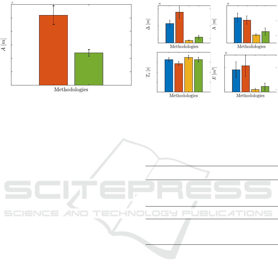
Figure 5: Mean and standard error of the cutting-induced
oscillations amplitude A on the Pinot Noir: sharp cut (red)
and controlled cut (green).
statistical analysis was performed. The mean and the
standard error of the measured oscillations amplitude
A, represented in Fig. 5, demonstrate a significant dif-
ference in the two cutting typologies. Considering
the project’s objective of minimising oscillations to
reduce the processing time of vision algorithms, the
trade-off between reducing oscillations solely caused
by cutting force and the additional 0.6 s in cutting
time was deemed highly beneficial. Consequently,
the cuts for the four methodologies were performed
using the second method, assuming similar results for
the cuts made at 45 degrees, with slightly higher av-
erages due to the bigger cutting surface.
Regarding the displacement from the rest position,
in Fig. 6 (top left), it is possible to appreciate the ef-
fectiveness of the proposed methods. The On−0 case
has an average displacement of 0.2 mm, with an ef-
fective displacement reduction of 87.2% compared to
the O f f −0 case. Similarly, the case On −45 has an
81.9% reduction compared to the case O f f −0. Note
that both average values are affected by a very low
standard error and that the On−45 case also performs
70.4% better than the O f f −0 case. Table 2 (top left)
synthesises the above results.
The vine oscillation is influenced by forces due to
the contact between the shears and the cane and forces
resulting from cutting. While these factors contribute
to the overall oscillation, the displacement of the vine
cane plays a crucial role in determining the amplitude
of the oscillation. Figure 6 (top right) shows that the
oscillations in the On −0 and On −45 cases achieve
a reduction of 69.1% and 51.6% respectively, com-
pared to the O f f −0 and O f f −45 cases. As re-
ported in Table 2 (top right), the average oscillation is
reduced to ≈ 0.002 m and 0.003 m in the On −0 and
On −45 cases, respectively, with very low standard
error. These results demonstrate the effectiveness of
0.5
2
4
10
-3
2.0
6.0
10.0
10
-3
5
10
15
20
0.1
1
1.5
10
-3
Figure 6: Mean and standard error: displacement from the
rest position (top left), oscillation amplitude (top right), set-
tling time (bottom left), normalised signal energy (bottom
right). Blue: O f f −0 case, red: O f f −45 case, yellow:
On −0 case, green: On −45 case.
Table 2: Mean and standard error: displacement from the
rest position (top left), oscillation amplitude (top right), set-
tling time (bottom left), normalised signal energy (bottom
right).
Case Study ∆ A
µ [m] σ
x
[m] µ [m] σ
x
[m]
O f f −0 2.2 ×10
−3
3.7 ×10
−4
6.8 ×10
−3
1.2 ×10
−4
O f f −45 3.6 ×10
−3
7.5 ×10
−4
6.2 ×10
−3
1.0 ×10
−4
On −0 2.8 ×10
−4
0.5 ×10
−4
2.1 ×10
−3
2.8 ×10
−4
On −45 6.5 ×10
−4
2.1 ×10
−4
3.0 ×10
−3
9.8 ×10
−4
Case Study T
a
E
µ [m] σ
x
[m] µ [m] σ
x
[m]
O f f −0 16.23 1.07 0.9 ×10
−3
0.3 ×10
−3
O f f −45 14.24 0.96 1.0 ×10
−3
0.4 ×10
−3
On −0 17.43 1.05 0.1 ×10
−3
0.3 ×10
−4
On −45 16.50 1.23 0.2 ×10
−3
0.1 ×10
−3
the proposed methods in reducing the amplitude of
the oscillations in both cases.
Figure 6 (bottom left) and Table 2 (bottom left)
show the average settling times between 14 and 17 s.
This variability is likely due to the heterogeneity of
the vine’s mechanical properties. The average of the
cases On −0 and On −45 is slightly higher than the
tests carried out without the observer. However, given
the high standard error of the data, an almost equal
settling time for all methodologies can be assumed.
Figure 6 (bottom right) shows that the proposed
methodologies significantly reduce the normalised
signal energy. Table 2 (bottom right) states that the
cases On −0 and On −45 exhibit a reduction in E by
88.8% and 80%, respectively. This reduction may in-
dicate that, during cutting, a lower amount of energy
is involved, which potentially means less alteration of
the system’s initial state.
ICINCO 2023 - 20th International Conference on Informatics in Control, Automation and Robotics
646

5 CONCLUSION
This paper introduced a force-sensor-free method-
ology to reduce grapevine cane oscillations during
robotic winter pruning. It relied on the momentum-
based observer algorithm and used proprioceptive
sensors for external force feedback. Experimen-
tal testing, with 200 randomised cuts on Pinot Noir
grapevines using a KUKA LBR iiwa7 manipula-
tor with a commercial shear system, demonstrated
a reduction in oscillation amplitudes, confirming the
method’s effectiveness. The goal is to create a cost-
effective and easily reproducible robotic system to
speed up winter pruning. In future, potential areas of
improvement include controlling shear blade forces
during cuts and integrating algorithms for optimising
robot-plant interactions to improve vine cane pruning.
ACKNOWLEDGEMENTS
The research leading to these results has been sup-
ported by both the PRINBOT project (in the frame
of the PRIN 2017 research program, grant number
20172HHNK5 002) and the COWBOT project (in the
frame of the PRIN 2020 research program, grant num-
ber 2020NH7EAZ 002). The authors are solely re-
sponsible for its content.
REFERENCES
Amabili, M. (2018). Nonlinear damping in large-amplitude
vibrations: modelling and experiments. Nonlinear
Dynamics, 93(1):5–18.
Botterill, T., Paulin, S., Green, R., Williams, S., Lin, J.,
Saxton, V., Mills, S., Chen, X., and Corbett-Davies,
S. (2017). A robot system for pruning grape vines.
Journal of Field Robotics, 34(6):1100–1122.
De Luca, A., Albu-Schaffer, A., Haddadin, S., and
Hirzinger, G. (2006). Collision detection and safe re-
action with the dlr-iii lightweight manipulator arm. In
2006 IEEE/RSJ International Conference on Intelli-
gent Robots and Systems, pages 1623–1630.
Epee, P., Schelezki, O., Parker, A., Trought, M., Werner, A.,
Hofmann, R., Almond, P., and Fourie, J. (2022). Char-
acterising retained dormant shoot attributes to support
automated cane pruning on vitis vinifera l. cv. sauvi-
gnon blanc. Australian Journal of Grape and Wine
Research, 28(3):508–520.
Guadagna, P., Fernandes, M., Chen, F., Santamaria, A.,
Teng, T., Frioni, T., Caldwell, D. G., Poni, S., Sem-
ini, C., and Gatti, M. (2023). Using deep learning
for pruning region detection and plant organ segmen-
tation in dormant spur-pruned grapevines. Precision
Agriculture.
Kaiser, J. (1990). On a simple algorithm to calculate the
’energy’ of a signal. In International Conference on
Acoustics, Speech, and Signal Processing, pages 381–
384 vol.1.
Katyara, S., Ficuciello, F., Caldwell, D. G., Chen, F., and
Siciliano, B. (2020). Reproducible pruning system on
dynamic natural plants for field agricultural robots.
Manuelli, L. and Tedrake, R. (2016). Localizing external
contact using proprioceptive sensors: The contact par-
ticle filter. In 2016 IEEE/RSJ International Confer-
ence on Intelligent Robots and Systems (IROS), pages
5062–5069.
Morlando, V., Teimoorzadeh, A., and Ruggiero, F.
(2021). Whole-body control with disturbance re-
jection through a momentum-based observer for
quadruped robots. Mechanism and Machine Theory,
164:104412.
Poni, S., Gatti, M., Palliotti, A., Dai, Z., Duch
ˆ
ene, E.,
Truong, T.-T., Ferrara, G., Matarrese, A. M. S.,
Gallotta, A., Bellincontro, A., Mencarelli, F., and
Tombesi, S. (2018). Grapevine quality: A multiple
choice issue. Scientia Horticulturae, 234:445–462.
Poni, S., Tombesi, S., Palliotti, A., Ughini, V., and Gatti,
M. (2016). Mechanical winter pruning of grapevine:
Physiological bases and applications. Scientia Horti-
culturae, 204:88–98.
Ruggiero, F., Cacace, J., Sadeghian, H., and Lippiello, V.
(2015). Passivity-based control of vtol uavs with a
momentum-based estimator of external wrench and
unmodeled dynamics. 72:139–151.
Ryll, M., Muscio, G., Pierri, F., Cataldi, E., Antonelli, G.,
Caccavale, F., and Franchi, A. (2017). 6d physical in-
teraction with a fully actuated aerial robot. In 2017
IEEE International Conference on Robotics and Au-
tomation (ICRA), pages 5190–5195.
Teng, T., Fernandes, M., Gatti, M., Poni, S., Semini, C.,
Caldwell, D., and Chen, F. (2021). Whole-body
control on non-holonomic mobile manipulation for
grapevine winter pruning automation.
Wang, J. and Olson, E. (2016). Apriltag 2: Efficient and
robust fiducial detection. In 2016 IEEE/RSJ Interna-
tional Conference on Intelligent Robots and Systems
(IROS), pages 4193–4198.
You, A., Sukkar, F., Fitch, R., Karkee, M., and David-
son, J. R. (2020). An efficient planning and control
framework for pruning fruit trees. In 2020 IEEE In-
ternational Conference on Robotics and Automation
(ICRA), pages 3930–3936.
Zahid, A., Mahmud, M. S., He, L., Heinemann, P., Choi, D.,
and Schupp, J. (2021). Technological advancements
towards developing a robotic pruner for apple trees:
A review. Computers and Electronics in Agriculture,
189:106383.
Sensorless Reduction of Cane Oscillations Aimed at Improving Robotic Grapevine Winter Pruning
647
