
Development of a Curling Stone Tracking System Using Infrared LEDs,
and an Accompanying Application
Yoshinari Takegawa
1 a
, Noa Sasaki
1
, Shimpei Aihara
2 b
and Fumito Masui
2 c
1
School of Systems Information Science, Future University Hakodate, Hokkaido, Japan
2
Department of Sport Science and Research, Japan Institute of Sport Sciences, Tokyo, Japan
Keywords:
Curling, Position Measurement, Infrared LED, Image Processing, Measurement Software.
Abstract:
The purpose of this study is the design and implementation of a real-time position measurement system for
use on curling stones. Often called ‘chess on ice’, curling is a sport that requires a high level of strategy.
Accordingly, how the stones move around the vast 40m curling rink constitutes important data. However,
in the unique environment of the icy and vast rink, it is difficult to monitor the position of the stones by a
simple method without hindering the players. Therefore, in our research, we proposed a system using infrared
LEDs and an infrared camera. Infrared LED modules are installed on the stones and the rink, and infrared
cameras installed around the edge of the rink film the LED modules and perform calibration. Then, using
four coordinates of the LED modules on the rink, the system employs perspective transformation technology,
which is a type of image processing. In so doing, it is possible both to measure the position of the stones, and
solve problems. Through experiments, performance evaluation was conducted to asses what degree of error
occurs in position measurement when the proposed system is used. Experiments were conducted on a curling
rink. The average error was 0.189m in the experiment at the curling rink.
1 BACKGROUND
Curling is a sport in which players slide stones on
ice, aiming to achieve a higher score than their op-
ponents. Its high level of strategy and skill has led
curling to be called ‘chess on ice’. However, to form
a strategy, it is necessary to consider various factors,
such as the current positions of the stones, the con-
dition of the ice, and the state of play, while skill is
dependent upon a player’s experience and intuition.
Furthermore, there is, even now, no established the-
ory regarding what causes the stones to curve as they
travel (Murata, 2022). Due to the complex and ad-
vanced element of strategy and the fact that technique
is dependent on players, there are few scientific ap-
proaches to curling, in comparison with other sports.
Nevertheless, Masui et al. have started research ti-
tled ‘Curling Science’ which is an initiative to cre-
ate new strategy support that integrates information
a
https://orcid.org/0000-0003-1947-0021
b
https://orcid.org/0000-0002-8513-0204
c
https://orcid.org/0000-0001-9979-8734
technology’
1
. This project involves research on dig-
ital curling (Ito and Kitasei, 2015), tactical analysis,
measurement of stone behavior, and sweeping (Gwon
et al., 2020; Won et al., 2018).
Digital curling refers to the proposal of a virtual
curling space, created using a computer’s physical
simulator, that acts as a space to enable discussion of
curling strategy. This concept has been developed by
a large number of people (Yamamoto et al., 2015).
In addition, systems, such as the Portable Tactical
Support DB System, have been developed to record
shots, stone layout, match scores, players taking part,
and the condition of the ice, on a tablet device (Masui
et al., 2015; Masui et al., 2016; Otani et al., 2016).
These works are examples of tactical support car-
ried out on a computer, but we consider it necessary
to apply the technologies to actual play and provide
support in real time. It is thought that grasping the po-
sitions of the stones is important as one factor towards
achieving this. The points that must be considered in
actual measurement of stone position are as follows:
• Measurement on ice
1
https://kaken.nii.ac.jp/en/grant/KAKENHI-PROJECT
-15H02797/
136
Takegawa, Y., Sasaki, N., Aihara, S. and Masui, F.
Development of a Curling Stone Tracking System Using Infrared LEDs, and an Accompanying Application.
DOI: 10.5220/0012182600003587
In Proceedings of the 11th International Conference on Sport Sciences Research and Technology Support (icSPORTS 2023), pages 136-143
ISBN: 978-989-758-673-6; ISSN: 2184-3201
Copyright © 2023 by SCITEPRESS – Science and Technology Publications, Lda. Under CC license (CC BY-NC-ND 4.0)

As curling is played on ice, room temperature is be-
low 10 degrees, and the curling rink maintains a tem-
perature of -5 degrees Celsius. Accordingly, the sys-
tem must be able to operate in this environment. Also,
it must be durable enough to run not only a few times,
but throughout the entire curling season.
• Not hindering players
As curling is played on a 40m-long rink, it is possi-
ble that installing a system on the rink will hinder the
players.
• Highly accurate position measurement
In curling, the stone closest to the centre of the house
obtains points, which is why stone position informa-
tion is important. The occurrence of a large calcula-
tion error would affect the outcome of a game. There-
fore, we require a system that can measure positions
across the entire 40m rink, without any large calcula-
tion errors.
In the peculiar environment of the icy and wide
rink, it is difficult to monitor the positions of the
stones by a simple method without hindering the play-
ers. To the extent of our knowledge, there is no ex-
isting stone-tracking system that meets the aforemen-
tioned requirements.
Therefore, in this research, we aim to develop a
curling-stone tracking system. In the proposed sys-
tem, where a hindrance to players is resolved by
mounting infrared LEDs on the stones and having an
infrared camera installed at the edge of the rink per-
forming image processing. In addition, we develop
applications that utilize the stone position information
measured by the stone tracking system. This applica-
tion provides a graphic presentation of the trajectories
of the stones, by projection mapping on the surface of
the rink.
2 RELATED RESEARCH
Many studies and methods have been implemented to
measure the position of people or things. There is
a method that uses Lidar, created by Velodyne Lidar
Inc., to measure position information in real time
2
.
Lidar is capable of measurement with an error of ap-
proximately 3cm. However, as Lidar measures on a
horizontal, measurement cannot be performed if there
is any obstacle between a Lidar sensor and the item to
be measured. For this reason, we consider it diffi-
cult to use Lidar for position measurement in curling,
which uses multiple stones. Lidar can recognize the
2
https://en.wikipedia.org/wiki/Lidar
Figure 1: Measurement Conditions.
shape of a stone if it is nearby, but fails when a stone
is further away.
There has been research on measuring the position
and angular velocity of curling stones, using video
and camera images (Hattori et al., 2023). With an
error of 2mm, the system is highly accurate. How-
ever, because the system is focused on accuracy and
aims to measure curl ratio, i.e., the way the stones curl
over a short distance, the photographic range is lim-
ited to approximately 4.5m. This differs from our re-
search, which aims for simple and wide-ranging mea-
surement. There is further research involving mea-
surement by cameras, though not targeted at curling
stones. In the research by Aoshima, measurement is
accurate to within 1.0mm, but measurement range is
limited to 1-4m (Tao et al., 2017). Furthermore, it is
necessary to prepare several cameras and install them
all facing the same direction. In contrast, our research
aims for a simple measurement method that covers the
wide area of the curling rink. There are also methods
that use Bluetooth or wireless LAN (Sawada et al.,
2016)(Tsuda et al., 2013). These methods are capable
of measuring across a range of approximately 100m,
however, measurement is only accurate to within sev-
eral meters. This makes it difficult to apply such
methods to curling, as an error of a few meters is too
large for a sport in which a few millimeters can define
a difference between winning and losing.
3 MEASUREMENT METHOD
3.1 System Installation
Figure 1 shows the conditions at the time of curling
stone position measurement. In this system, an LED
module is installed on top of each curling stone, and
LED modules are also installed under the ice of the
curling rink, with a module installed every 1m along
the length of the rink, up to 10m, and a module in-
stalled every 1m across the width of the rink, up to
3m, making a total of 30 modules. Also, an infrared
camera is installed at the edge of the rink.
Development of a Curling Stone Tracking System Using Infrared LEDs, and an Accompanying Application
137
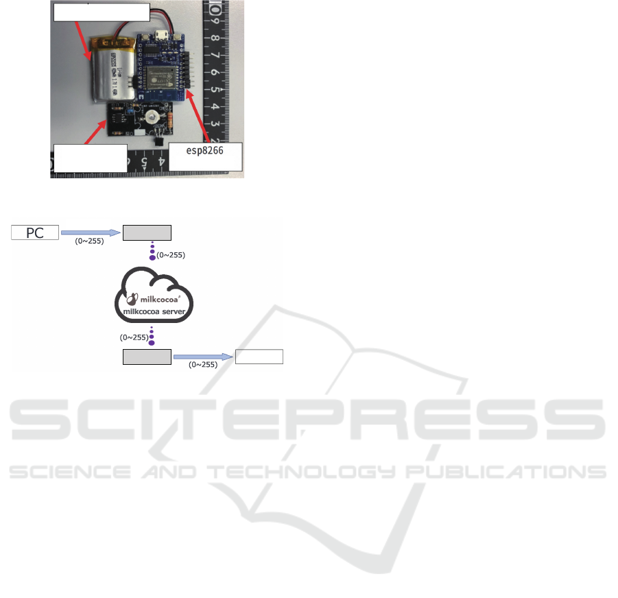
Figure 2: Modules Installed on the Stone.
Figure 3: Flow up to Lighting Up/Turning off.
3.1.1 Stones
Figure 2 presents the LED module and esp8266 mod-
ule that are installed on the top of a curling stone.
To light up the LED module on the curling stone, an
esp8266 module, capable of Wi-Fi connection, was
used. This enables remote adjustment of the bright-
ness of the LED module. In addition, the esp8266
module is powered by a lithium ion battery, meaning
that it can be controlled wirelessly and so will not stop
working during play. Next, the flow up to the lighting
of the LED module is presented in Figure 3. First,
esp8266 module 1 is wired to the computer and a
value between 0 and 255, representing the light inten-
sity of the LED module, is uploaded by serial commu-
nication. Then, the value received by esp8266 module
1 is sent to the data store of the Milkcocoa server. The
value in the data store is received by esp8266 module
2, then sent to the LED module, causing it to light up
or turn off. The LED module turns off when the value
is 0, and lights up when the value is anything other
than 0.
3.2 Flow of Position Measurement
• Calibration
The coordinates of the LED module, which are nec-
essary for position measurement, are recorded. Then
calibration is performed, by the following process.
1. Designate the range as the four corners of the rink
at which LED modules are installed.
2. Light up the LED modules within the range, one
by one.
3. Adjust the light intensity until the surface area of
LED module light detected by the infrared camera
is 10 pixels (+-3).
4. Extract the outline of the LED module light and
record the coordinates at the centre of the outline.
As long as the infrared camera is not moved, calibra-
tion needs only be performed once. Also, LED mod-
ule coordinate measurement at the time of calibration
is carried out automatically once implemented. Thus,
LED modules are lit up in consecutive order from
no.1, and the program automatically measures the po-
sition, in meters, at which the modules are present on
the rink.
• Stone Sliding
Position measurement is made possible by using the
values obtained in calibration along with perspective
transformation technology, which is a type of image
processing. The flow of the stone position measure-
ment is as follows:
1. Slide a stone onto which a LED module is
mounted
2. Calculate four coordinate points (hereafter re-
ferred to as reference points) froom the nearest
LEDs surrounding the stone’s LED module
3. Using the four reference points, carry out perspec-
tive transformation
3.2.1 Perspective Transformation
Perspective transformation is an image processing
technique for depicting a three-dimensional object
position on a two-dimensional plane. In the layout
of the proposed system, the infrared camera is tilted
slightly downward to film the LED modules on the
rink. However, as the camera image reflects a three-
dimensional space, distances of the same length ap-
pear different in the foreground to the background.
Therefore, perspective transformation is used to cor-
rect the image to a two-dimensional plane. During
this process, first the image position of LED mod-
ule on top of the stone is extracted in pixels. Next,
a perspective transformation series is calculated from
the surrounding four reference points obtained in cal-
ibration. By this process, the image is transformed
to a two-dimensional plane, and stone position can be
measured.
icSPORTS 2023 - 11th International Conference on Sport Sciences Research and Technology Support
138

Figure 4: Program Execution Screen of Position Measure-
ment Application.
3.2.2 Position Measurement Application
Figure 4 shows the program execution screen of the
position measurement application. The application
has three modes, and stone position measurement is
made possible by implementing the three modes in
order.
1. Rink mode: In this mode, the range of calibration
is decided. This is done by setting red circles at
the positions corresponding to the corners of the
rink. The reason it is necessary to set the range
is that, because curling is an indoor sport, some-
times indoor lighting or light reflection off walls
can prevent calibration from being carried out suc-
cessfully.
2. Reference mode: In this mode, the infrared LED
modules within the range set in Rink mode are
calibrated. Calibration comprises lighting up the
LED modules one by one and recording the x and
y coordinates and light intensity of each module.
3. Position mode: This mode records the position of
a stone that has been thrown.
Next, we explain the program execution screen.
‘A’ in Figure 4 presents and records the x coordinate,
y coordinate and light quantity of each LED module,
obtained in calibration. The numbers from 0 to 5 on
the vertical axis and 1 to 20 on the horizontal axis rep-
resent the positions of the LED modules installed on
the rink, and correspond to 1m, 2m, ... 20m. The posi-
tions of LED modules for which current coordinates
were obtained during calibration are represented by
purple squares, the positions of which can be altered
manually.
‘B’ in Figure 4 represents the position information
of a stone thrown when using Position mode. Here,
the distance in the x and y directions, and the pixel
position, are expressed.
‘C’ in Figure 4 presents the keys used to oper-
ate the program, as well as the mode status and LED
module light intensity. From left to right, the figure
presents the keys used, a simple explanation of key
operation, and the current mode and LED light inten-
sity in red letters. The functions assigned to each key
are described in detail below.
• ‘Space’ key This key is used to switch between
’Start’ and ’stop’ in the program. The program is
in the ’Stop’ state at the time of start-up, at which
time pressing the key once switches to ’Start’ sta-
tus and the infrared camera starts up. Pressing
the key once more switches back to ’Stop’ status,
causing the camera to stop recording.
• ‘Enter’ key This key is used to switch between
Rink mode, Reference mode, and Position mode.
The program is in Rink mode at the time of start-
up. In this state, pressing the enter key once tran-
sitions to Reference mode, and pressing the key
once more transitions to Position mode. Pressing
the key once more transitions to Rink mode again.
• ‘g’ key This key can only be used in Reference
mode. Pressing the key initiates calibration, caus-
ing the LED modules to light up in order from the
module closest to the connection point, and the
x coordinate, y coordinate, and light quantity of
each module to be recorded automatically.
• ‘j’ key, ’k’ key These keys can only be used in
Reference mode. Pressing the ’j’ key increases
the light intensity of the illuminated LED mod-
ule. Pressing the ’k’ key decreases the light inten-
sity. Light intensity can be adjusted within a range
from 0 to 255.
• ‘z’ key This key can only be used in Reference
mode. Pressing the key deletes the coordinates
and light intensity data of the currently selected
LED module.
• ‘d’ key This key can only be used in Reference
mode. After calibration has ended, pressing this
key saves the coordinates and light intensities ob-
tained in calibration.
3.3 Implementation
The program used when calibrating and measuring
stones employs the following devices. The PC used
was a Lenovo ThinkPad (CPU Intel(R) Core(TM) i7-
4650U 1.70GHz); software development on the PC
was carried out using Visual C++ and OpenCV library
and openFrameworks library on Windows 10. To film
the curling stones on the wide rink, from diagonally
above, an infrared camera (DMK23UX236) was in-
stalled on top of a tripod with a maximum height
of 3.6m (ManFrott SKU1004BAC), and an IR filter
(NEEWER IR950) was attached to the infrared cam-
era to block visible light.
Development of a Curling Stone Tracking System Using Infrared LEDs, and an Accompanying Application
139
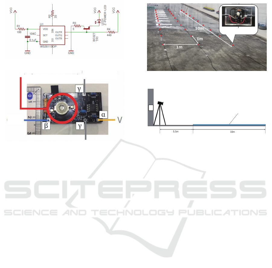
Figure 5: Infrared LED Module Circuit Diagram.
Figure 6: Infrared LED Module Circuit Board.
3.4 LED Module
3.4.1 Specification
Figure 5 shows the circuit diagram of the propsed
LED module. The parts used in the circuit board con-
sist of an infrared LED, resistor, capacitor, transistor
and micro-processor. Next, Figure 6 shows the actual
circuit board, with infrared LED attached, that was
installed on the rink and the stones. The V, GND,
In, and Out parts of circuit boards are connected to
control multiple substrates. A circuit board itself, in-
cluding its component parts, has a length of 2.4mm,
width of 3.7mm, and height of 0.9mm. The red circle
in the centre of the figure is the infrared LED.
3.4.2 Operation in Curling
In this research, we embedded infrared LED modules
in the ice of a curling rink. The reason for this is that
installing the modules on the surface of the rink would
prove a hindrance to players, and modules would have
to be re-installed every time the rink was used. How-
ever, there is still the problem that the LED modules
are exposed, besides which it is uncertain whether
they can operate for a long time within the ice. To
resolve these issues, the LED modules were coated
with crystal resin. First, the circuit board is inserted
into an 8mm plastic case and affixed with a glue gun.
Then, resin is poured into the case and left to harden
for 24 hours.
Figure 7: Distribution of LEDs Embedded in the Rink.
Figure 8: Arrangement of the System in the Curling Hall.
4 EXPERIMENTS
The aim of this experiment was to verify the accuracy
of stone position measurement in the case of having
altered certain conditions (distance between camera
and LED lines, camera angle).
Experiment Environment. The experiment took
place at the Kawanishi Construction Curling Hall, in
Kitami, Hokkaido.
In addition, Figure 7 presents the LED lines laid
out on the rink before it was covered with ice. 10m
worth of LED modules were installed at 1m intervals
along the length of the rink, and 3m worth at 1m in-
tervals across the width of the rink.
The infrared camera was installed 5.5m in front of
the edge of the rink. This is because the construction
design of the rink makes it impossible to position the
camera any further away, and the camera cannot de-
tect all the LED modules if it is positioned any closer
to the rink. The arrangement of the system in the curl-
ing hall is shown in Figure 8.
Experiment Method. Regarding the procedure, af-
ter filming with the infrared camera and performing
calibration, an LED module representing a curling
stone is placed at the point 1m on the length and 1m
on the width of the rink, and position measurement is
begun. Then, the measured value of the position on
the screen is obtained. Once this value is obtained,
the LED module is shifted 0.25m lengthwise, while
icSPORTS 2023 - 11th International Conference on Sport Sciences Research and Technology Support
140

Figure 9: Measurement Points on the Curling Rink.
maintaining a position of 1m horizontally. This is re-
peated until the module reaches the 10m point. After
reaching a length of 10m, the module is shifted 0.25 at
a time along the width of the rink, until it reaches the
2m point. Then, the module is returned to the point
1m along the length of the rink and the whole process
is repeated until the module reaches the 10m point.
As shown in Figure 9, we measure 37 points on the
length of the rink and 9 points on the width of the
rink, making a total of 333 points measured.
Evaluation Indices. Once position measurement
was complete, we compared the original values and
the obtained values. We calculated the position mea-
surement error in the case of having reduced the ref-
erence points as shown in Figure 10.
Results. The average error was 0.189m. The max-
imum error was 0.63m, at the point at length 9.75m
and width 2.75m. There was no problem regarding
the operation of the LED modules embedded in the
ice.
Next, we describe the the results when reference
points are reduced. The transition of the average error
in the case of reduced reference points is presented in
Figure11.
Figure 10: Measurement Range when Reference Points are
Reduced (On Curling Rink).
Figure 11: Transition of Average Error When Reference
Points are Reduced (Curling Rink).
Consideration. Regarding position measurement
accuracy, in the same manner as the preliminary ex-
periment, the further away the measurement point
was, the larger the measurement error became. This
is because, at a distant point, measurement error be-
comes large if detection of the LED support is out by
even one pixel.
Overall, the error was larger than in the prelim-
inary experiment. This was because refraction was
caused by the ice of the curling rink, causing the op-
tical axis of the LED module to shift forward. At ev-
ery point on the rink, it was confirmed that even if
the stone LED was actually placed in the correct po-
sition, the measurement result was further away. As a
revision method to compensate for for refraction, we
reduced all the length measurement results in the esti-
mated values by 0.100. In this case, the average error
became 0.129m.
Even inside the ice, the LED modules within the
LED line operated successfully. This is because the
modules were protected from moisture and cold by a
Development of a Curling Stone Tracking System Using Infrared LEDs, and an Accompanying Application
141
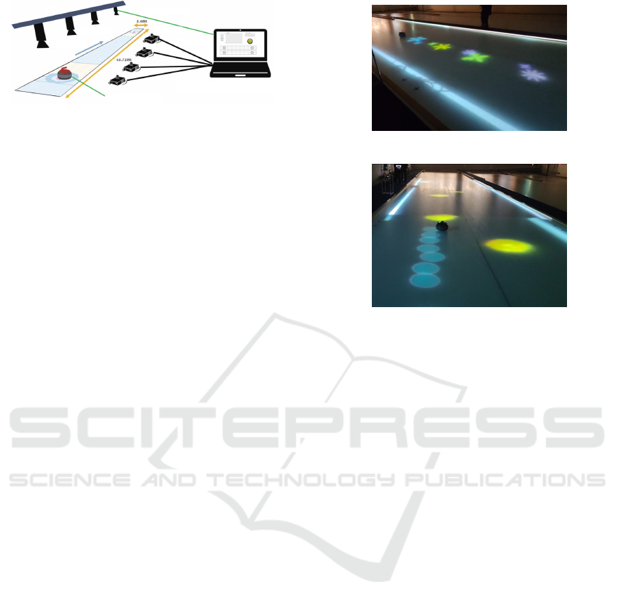
Figure 12: System Structure.
resin coating.
When the reference points are reduced, the four
reference points surrounding the stone LED, which
are used in perspective transformation, become fur-
ther away. As a result, the influence of LED sup-
port detection error at these reference points becomes
greater.
5 APPLICATION
As mentioned in Section 1, this research is targeted at
curling beginners, children, spectators, etc., and aims
to enable people to enjoy curling, and learn all its
component techniques. The target users are beginners
with no special knowledge or skill related to curling,
and curling spectators. The games developed in the
Curling Projection Mapping research include a game
played on the rink and a game that uses a smartphone
application.
5.1 Curling Projection Mapping
The system structure of Curling Projection Mapping
is presented in Figure 12. Infrared LEDs are attached
to the curling stones, and the trajectory of those stones
is recognized by multiple infrared cameras installed
on the ceiling. The corresponding position informa-
tion is estimated by a computer, which generates an
image. Then, the generated image is projected on the
rink in real time by multiple projectors.
In Curling Projection Mapping, there are a total of
three games that we have developed: ‘MiracleFlower’
and ‘CoinCollector’, which are games projected onto
the rink, and ‘StoneSpeedChecker’, which is a tablet
application. Each type of game is described below.
Here we explain about ‘MiracleFlower’ and ‘Co-
inCollector’, which are the games involving projec-
tion on the rink.
MiracleFlower. As shown in Figure 13, ‘Miracle-
Flower’ is a simple game in which flowers bloom
following the trajectory of a curling stone. Players
are free to slide the stones however they wish, with-
out considering direction, velocity, and so on, which
Figure 13: Actuar usage of ‘MiracleFlower’.
Figure 14: Actuar usage of ‘CoinCollector’.
means that even beginners or people with no curling
knowledge can enjoy the game. In addition, specta-
tors can also enjoy watching the graphics of Miracle-
Flower.
CoinCollector. As shown in Figure 14, ‘CoinCol-
lector’ is a game in which players aim to slide stones
onto coins scattered across the rink, with the winner
being the player who collects the most points. With
its concept of aiming for as many targets as possible
in a single turn, this is a novel game that does not
conform to existing curling rules, although it enables
players to experience the thrill of competing.
5.2 Tablet Application
Here we introduce our tablet application, ‘Stone-
SpeedChecker’. In StoneSpeedChecker, as shown in
Figure 15, a tablet is installed on a stone and the cur-
rent velocity of the stone is presented in real time,
based on the position information generated by the
tracking system. The aim of this application is for the
sweepers to get an accurate grasp of the speed of the
stone. The sweepers announce to their team mem-
bers the ten-zone value that expresses where on the
house the stone will stop. Accordingly, it is essen-
tial for sweepers to grasp the speed of the currently
sliding stone in real time. The speed display meter
is equipped with a function that rotates the meter in
response to the rotation of the stone, to enable the
sweepers to read the speed smoothly even when the
stone rotates. The angle of rotation is estimated based
on the tablet’s internal geomagnetic sensor. In addi-
icSPORTS 2023 - 11th International Conference on Sport Sciences Research and Technology Support
142

Figure 15: Actuar usage of ‘StoneSpeedChecker’.
tion to aiding practice, this application can be used to
confirm the state of the stones and rink in night prac-
tice.
6 CONCLUSION
In this research, we developed an image-processing
based real-time curling stone tracking system. AS a
result of analyzing the peculiarities of the curling rink
and the game itself, we adopted an image-processing
based measurement method by infrared LED and in-
frared camera. In addition, we actually implemented
the system and, after conducting a preliminary exper-
iment, involving altering the infrared camera position,
inside the university, we conducted an experiment in
the real environment of the Kawanishi Construction
Curling Hall in Kitami. The average measurement
error was 0.189m in the curling venue experiment,
demonstrating that it was possible to measure with a
high degree of accuracy while using a single camera.
Furthermore, as applications that utilize our tracking
system, we developed two kinds of game incorporat-
ing projection mapping on the rink.
ACKNOWLEDGEMENTS
This work was supported by the “Functional Develop-
ment Project for Resilient Athlete Support” of Japan
Sports Agency.
REFERENCES
Gwon, J., Kim, H., Bae, H., and Lee, S. (2020). Path plan-
ning of a sweeping robot based on path estimation of
a curling stone using sensor fusion. Electronics, 9(3).
Hattori, K., Tokumoto, M., Kashiwazaki, K., and Maeno,
N. (2023). High-precision measurements of curling
stone dynamics: Curl distance by digital image analy-
sis. Proceedings of the Institution of Mechanical En-
gineers, Part P: Journal of Sports Engineering and
Technology, 237(2):102–108.
Ito, T. and Kitasei, Y. (2015). Proposal and implementa-
tion of ”digital curling”. In 2015 IEEE Conference on
Computational Intelligence and Games (CIG), pages
469–473.
Masui, F., Hirata, K., Otani, H., Yanagi, H., and Ptaszynski,
M. (2016). Informatics to support tactics and strate-
gies in curling. International Journal of Automation
Technology, 10(2):244–252.
Masui, F., Ueno, H., Yanagi, H., and Ptaszynski, M. (2015).
Toward curling informatics — digital scorebook de-
velopment and game information analysis. In 2015
IEEE Conference on Computational Intelligence and
Games (CIG), pages 481–488.
Murata, J. (2022). Study of curling mechanism by preci-
sion kinematic measurements of curling stone’s mo-
tion. Scientific Reports, 12(1).
Otani, H., Masui, F., Hirata, K., Yanagi, H., and Ptaszyn-
ski, M. (2016). Analysis of curling team strategy
and tactics using curling informatics. In Correia,
P. P. and Cabri, J., editors, icSPORTS, pages 182–187.
SciTePress.
Sawada, K., Hanada, Y., and Mori, S. (2016). User-
installable indoor positioning system using a wi-fi
beacon and pdr module. Journal of Information Pro-
cessing, 24(6):843–852.
Tao, T., Chen, Q., Feng, S., Hu, Y., Da, J., and Zuo, C.
(2017). High-precision real-time 3d shape measure-
ment using a bi-frequency scheme and multi-view sys-
tem. Appl. Opt., 56(13):3646–3653.
Tsuda, Y., Kong, Q., and Maekawa, T. (2013). Detecting
and correcting wifi positioning errors. In Proceedings
of the 2013 ACM International Joint Conference on
Pervasive and Ubiquitous Computing, UbiComp ’13,
page 777–786, New York, NY, USA. Association for
Computing Machinery.
Won, D.-O., Kim, B.-D., Kim, H.-J., Eom, T.-S., Muller,
K.-R., and Lee, S.-W. (2018). Curly: An ai-based
curling robot successfully competing in the olympic
discipline of curling. In Proceedings of the Twenty-
Seventh International Joint Conference on Artificial
Intelligence, IJCAI-18, pages 5883–5885. Interna-
tional Joint Conferences on Artificial Intelligence Or-
ganization.
Yamamoto, M., Kato, S., and Iizuka, H. (2015). Digital
curling strategy based on game tree search. In 2015
IEEE Conference on Computational Intelligence and
Games (CIG), pages 474–480.
Development of a Curling Stone Tracking System Using Infrared LEDs, and an Accompanying Application
143
