
Design of Modular and Distributable Automation Software for PLCs
Oscar Miguel-Escrig
a
, Isabel Rosell
´
o-Gonz
´
alez and Julio-Ariel Romero-P
´
erez
b
Departament d’Enginyeria de Sistemes Industrials i Disseny, Universitat Jaume I,
av. de Vicent Sos Baynat, Castell
´
o de la Plana, Spain
Keywords:
Distributed Control System, Grafcet, IEC 60848, IEC 61131, PLCs.
Abstract:
Design and maintainability of modular automation software are common concerns nowadays. Common prac-
tice in industry usually overlooks the design phase of software, jumping directly into the coding phase, which
typically results in poorly readable and maintainable code. In this work, it is shown how modular and hier-
archically structured design of discrete event control systems, which is supported by Grafcet models, can be
subsequently implemented in several devices distributed across the fieldbus. Besides, the resulting software
is more readable and maintainable due to its similarities with the proposed Grafcet model. An example is
provided showing how a distributed application can be tested in a centralized fashion.
1 INTRODUCTION
Automation software in industry is mainly imple-
mented in devices called Programmable Logic Con-
trollers (PLC). Their usage is extended across indus-
try due to their degree of standardization, their accep-
tance and accumulated know-how among practition-
ers and the support provided from institutions and re-
lated companies.
Different aspects surrounding PLCs are standard-
ized in the norm IEC 61131 (IEC, 2013), which is
widely adopted among the control community. PLCs
from different suppliers are programmed using Inte-
grated Development Environments (IDEs) based on
the standard IEC 61131, which interpret and incorpo-
rate in their programming environment the principles
of the standard, enabling portability to different ex-
tents.
It is worth mentioning that, in the context of dis-
tributed control systems, standard IEC 61499 (Zoitl
and Lewis, 2014) has been proposed to implement au-
tomation software. Despite the fact that its software
components are based on IEC 61131’s, IEC 61499 is
not as spread across industry as IEC 61131. However,
remarkable efforts are being made from the industry
domain and the academia to develop and integrate au-
tomation software according to IEC 61499, (Lyu and
Brennan, 2021).
The standard IEC 61131 defines in its third
a
https://orcid.org/0000-0002-2472-2038
b
https://orcid.org/0000-0003-3397-2239
part (IEC 61131-3) the programming languages that
can be used to implement the automation software.
Namely, these languages are Sequential Function
Chart (SFC), Function Block Diagram (FBD), Lad-
der Diagram (LD), Structured Text (ST) and Instruc-
tion List (IL). The first three languages are graphical,
and the remaining two textual. A project according to
IEC 61131 can be composed of several Program Or-
ganization Units (POU) each of them programmed in
the language of preference. Each of the languages de-
fined in the standard has its own strengths, which can
be exploited in the coding process. Despite the flex-
ibility and variety of languages, LD and ST are the
most used nowadays, (PLCopen, 2019).
Before starting coding, it is advisable to properly
define the system’s functionality with an appropriate
model. This step is generally overlooked in industry
because it is perceived as an unnecessary step that de-
lays code development. Some studies like (Johnson,
2007; Ljungkrantz et al., 2011) point out that this un-
deruse of models is due to strong time constraints and
to a lack of tools for automatically obtain control soft-
ware from models. However, coding directly from
the textual definition of the system’s behavior leads to
possible delays and results in harder to maintain code
since no formal definition of the behavior using mod-
els has been made.
There exist several tools for modeling the behav-
ior of automation systems which have been proved
in practice. Some examples of these tools are Con-
trol Interpreted Petri Nets, Grafcet diagrams or UML
Miguel-Escrig, O., Roselló-González, I. and Romero-Pérez, J.
Design of Modular and Distributable Automation Software for PLCs.
DOI: 10.5220/0012183700003543
In Proceedings of the 20th International Conference on Informatics in Control, Automation and Robotics (ICINCO 2023) - Volume 2, pages 135-141
ISBN: 978-989-758-670-5; ISSN: 2184-2809
Copyright © 2023 by SCITEPRESS – Science and Technology Publications, Lda. Under CC license (CC BY-NC-ND 4.0)
135

state diagrams. The obtained models allow a formal
description of the behavior, thus avoiding the ambi-
guities that a textual description can induce. In this
work, Grafcet diagrams, defined in the IEC 60848
(IEC, 2002), which are state-transition diagrams well-
known in the automation field, will be used to model
the behavior of discrete event control systems.
Grafcet diagrams and SFC language of standard
IEC 61131 are similar since both have the step-
transition concepts at its base. This makes the imple-
mentation of discrete event controller in SFC easier
to read and understand compared with implementa-
tions of controllers in other languages of the standard.
Thus, the usage of SFC results in a more maintain-
able code. Furthermore, due to the similarities be-
tween Gafcets and SFC, the formal description of the
controller behavior in Grafcet models can be easily
obtained from the SFC code, even if it is modified.
The aim of this work is to show that modular de-
sign enables for a modular implementation, enhanc-
ing the capability of the software to be distributed
across fieldbus devices, maintaining the structural hi-
erarchy of the Grafcet model. The translation step
from the model to the implementation is out of the
scope of the work since it has been detailed in the
literature (Julius et al., 2017; Schumacher and Fay,
2014). However, the usage of SFC for implementing
structuring mechanisms will be also explored. Be-
sides, aspects like readability and maintainability will
be shown to be enhanced through SFC implementa-
tion from GRAFCET diagram.
The structure of the work is as follows. In Sec-
tion 2 some preliminary discussion is made with
regard to the modeling and implementation of dis-
tributed automation software. In Section 3 the pro-
cedure for the design and implementation of the soft-
ware is explained. Section 4 presents the platform
used for validating the results, together with the mod-
eling and implementation details. Finally, in Section 5
de conclusions about this work are drawn.
2 PRELIMINARY NOTES
2.1 Modeling
Among the different modeling techniques available,
Grafcet diagrams, defined in the standard IEC 60848,
are a well-known tool in the field of control engi-
neering since this kind of diagrams form part of the
contents studied in higher education and technical
schools of the automation branch.
This modeling language allows the designer to de-
fine the general behavior of an automation system
regardless of the particular implementation details,
leaving their definition for subsequent and more de-
tailed design rounds or directly for the implementa-
tion.
Grafcet diagrams allow defining the detailed be-
havior of discrete event systems through a modular
and hierarchical design. This is accomplished, in part,
because of the language elements, which cover most
of the possible situations that can be found in actual
applications. Besides, the user has the possibility of
modeling the functioning of a whole system through
different partial Grafcet diagrams, enabling a modular
design.
To coordinate the different partial Grafcets that
can result from the design process, the norm provides
some mechanisms for hierarchically structuring the
functioning. In particular, the modeling mechanisms
are enclosures, macro-steps and forcing orders. The
particularities and rules concerning these mechanisms
are defined in the norm, and will not be further dis-
cussed. In this work, forcing orders will be used as
structuring mechanism since they enable for a hierar-
chical design.
It is worth noticing that these principles of mod-
ular design, hierarchy and abstraction in the behavior
definition, are not tied to a given physical device. In
this sense, there is not any hindrance to use Grafcet
diagrams for modeling distributed automation appli-
cations.
2.2 Implementation
The standard IEC 61131 in its third part offers five
programming language for implementing automation
software, each of them with their own properties
which make them more suitable than another lan-
guage for a given task.
In (Bonfatti et al., 1997), a discussion about the
roles of the language in IEC 61131 was provided.
SFC was highlighted as the most suitable to sup-
port the initial phases of PLC software development.
Several characteristics that endorsed SFC were men-
tioned: 1) High expressive power, 2) Graphic formal-
ism, 3) Support to preliminary design, 4) Support to
detailed design, 5) Natural connection with other lan-
guages and 6) Support to software fragmentation.
Due to these characteristics, SFC is recommended
for early design and to structure any application, leav-
ing the remaining languages to auxiliary tasks as
further specifying or implementing specific parts of
code. According to this, a hierarchy was defined in
(Bonfatti et al., 1997) between the IEC 61131 lan-
guages, regarding to their capabilities in different cod-
ing phases and to their level, which is presented in
ICINCO 2023 - 20th International Conference on Informatics in Control, Automation and Robotics
136

SFC
ST
FBD IL
Level
high
low
Phases
codingdesignanalysis
LD
Figure 1: Hierarchy of IEC 61131 languages according to
(Bonfatti et al., 1997).
Figure 1. This recommendation for the implementa-
tion will be kept in this work since it allows main-
taining the structure and hierarchy defined in Grafcet
models.
Since SFC language is very close to Grafcet mod-
eling, being both of them state diagrams, the com-
ments made regarding the applicability of Grafcet
models to design of distributed automation software,
also apply for SFC’s implementation. However, it
is important to notice that, while Grafcet models
can theoretically split steps across devices, (Miguel-
Escrig et al., 2020; Wiesmayr et al., 2021), SFC’s im-
plementation is tied to a single device. This aspect
will have to be considered in the modeling process.
Regarding the distribution of programs developed
under the IEC 61131 standard, it should be noted that,
unlike the IEC 61499, the IEC 61131 is highly tied
to the device where the code is implemented. This
standard, however, supports communication between
devices. The information exchange is supported in
the standard by access paths mechanisms. Alterna-
tively, other communication approaches can be used,
like Modbus or OPC.
3 FOLLOWED PROCEDURE
The procedure followed for the development of dis-
tributable automation software consists of a design
phase using Grafcet and an implementation phase us-
ing SFC as the main language, using the rest of lan-
guages of the IEC 61131 for further code developing
or adding some specific feature.
In the design phase, the process starts by identify-
ing the independent “tasks” that compose the whole
system behavior. The tasks are delimited according
to three principles, namely, interaction between tasks,
virtual modularity and physical modularity.
Reducing the interaction between tasks allows
lowering the communication network traffic, there-
fore, problems associated with the communication
such as packet losses or delays have a lesser impact
on the systems’ performance.
A differentiation has been made with regard to
the principle of modularity, which has been split be-
tween virtual and physical. Both aspects are equally
important and they take into account different char-
acteristics of the system. Under the physical modu-
larity, there are gathered aspects as plant layout or re-
usability of components (e.g. conveyors) in other pro-
cesses. Whereas by virtual modularity, all the aspects
regarding the software design and implementation are
gathered such as PLCs used, programs re-usability,
fieldbus constraints, etc.
With the different tasks identified following as
much as possible these principles, a Grafcet model
is designed for each of them. If needed, several par-
tial Grafcets are designed to correctly characterize
the behavior of the task. Afterward, a main Grafcet
model functioning as a coordinator between the pre-
vious partial Grafcets is designed. This main Grafcet
is in a hierarchically higher position with regard to
the partial Grafcets modeling the tasks and contains
structuring mechanisms like forcing orders or enclo-
sures. In this main Grafcet are included the coordina-
tion tasks for the normal operation of the process and
also stoppage or maintenance procedures.
Once the behavior of the system has been mod-
eled, with the desired degree of precision, through
different Grafcets, the implementation in IEC 61131
languages can begin. The language of choice for this
work is SFC due to its similarities with the developed
Grafcet models. The methodology for implementing
most of Grafcet model elements in SFC has been pre-
sented in (Schumacher and Fay, 2014). Following
the procedure explained in that paper the functioning
of each partial Grafcet is implemented in a different
POU, being the forcing orders the remaining aspect to
implement since an implementation guideline has not
been provided for the structuring mechanism.
For the scope of this work, it has only been con-
sidered forcing orders that empty the marking of a
Grafcet and forcing orders that initialize the function-
ing of a partial Grafcet to a given step.
According to the IEC 61131 standard, each SFC
network must always have at least one step active.
Therefore, to implement the aforementioned forcing
orders in a SFC that implements a forced Grafcet, we
propose to include an additional step symbolizing the
empty marking state. This new step, not included in
the developed partial Grafcet, will be implemented as
the initial step for the SFC network and will be placed
before the expected initial step for the functioning.
Design of Modular and Distributable Automation Software for PLCs
137
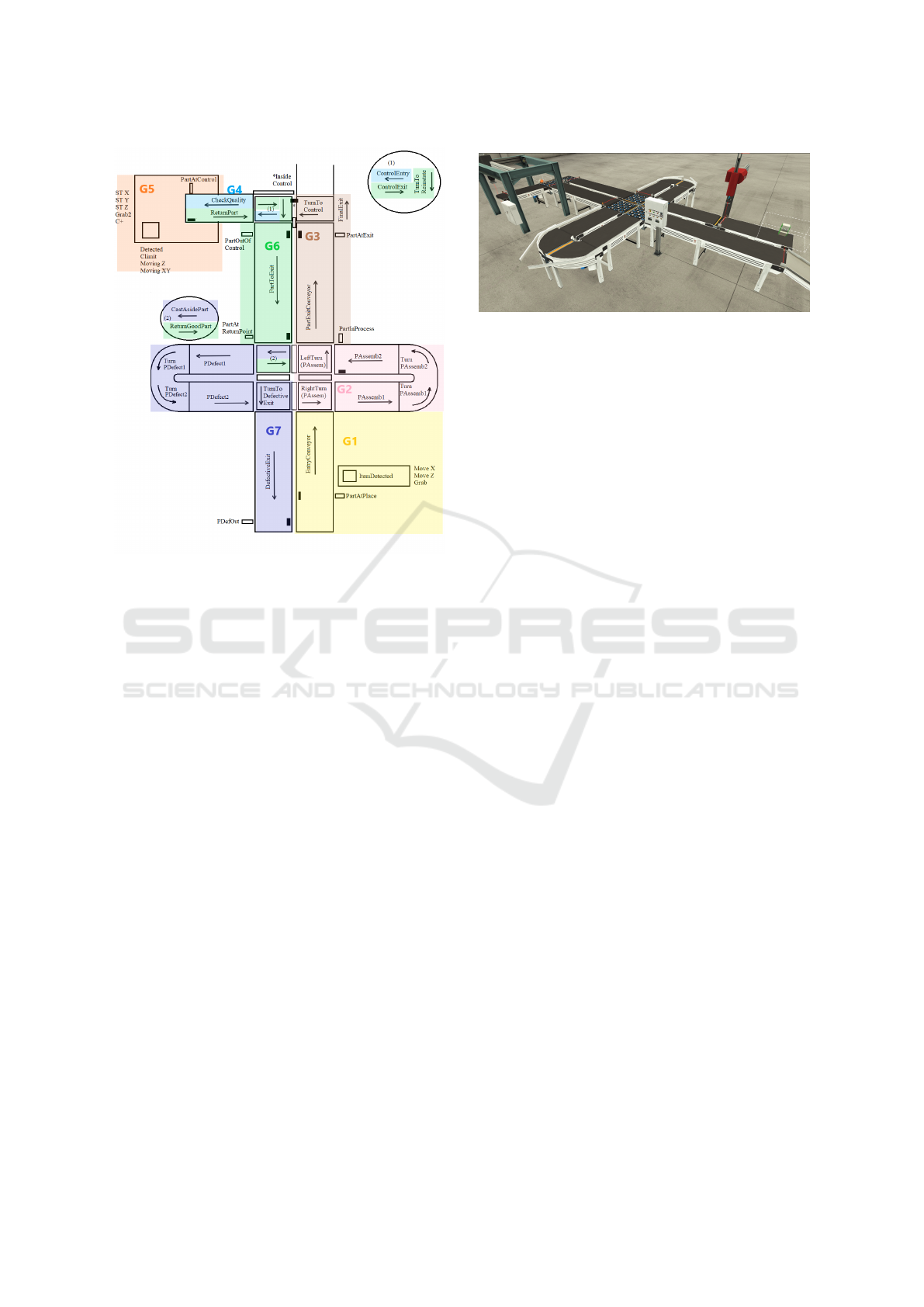
Figure 2: Diagram of the system with modeled Grafcets.
An additional always true transition will be included
after the new step. Besides, some mechanism to ini-
tialize and pause the execution of SFC networks must
be used. In Codesys, for instance, the flags SFCInit
and SFCPause play this role (Codesys, 2022).
To implement the forcing order in the SFC that
implements the functioning of a Grafcet that forces
another Grafcet, it is only required to modify the state
of the flags of the forced SFC accordingly. If the SFC
must return to its initial step, SFCInit is activated and
it will transition to the initial functioning step through
the always true transition included. If the SFC must
simulate an empty behavior, SFCInit and SFCPause
must be activated.
4 EXPERIMENTAL VALIDATION
4.1 Platform Presentation
The system under study is formed by a combination
of different conveyors, robots and sensors. The aim of
this system is to hold an assembling process in which
a lid is put onto a base. In addition, a quality control
is stochastically realized upon some of the assembled
pieces. The depiction of the system is presented in
Figure 2.
The normal operation of the system starts when
the Start Button is activated. Then, lids and bases
arrive alternatively through the entry conveyor. The
Figure 3: Digital model of the physical system in Fac-
tory IO.
robot in charge of the assembly takes one lid and puts
it on top of the base that comes after. Once the assem-
bly process is done, the part goes through a group of
perpendicular and round conveyors. Here, a series of
manual operations are conducted on the part to obtain
the final product. Then the final product is taken out
of the system by another set of conveyors.
The final products selected to pass the quality con-
trol are deviated towards the robot where it is carried
out. This is done once the manual operation has been
realized and before the piece leaves the system. Once
the product has passed the quality control an operator
establishes whether it has to be cast aside or not. If the
product has good quality, it is returned to the normal
exit. If the product has to be cast aside, it goes out of
the system though another set of conveyors, where an
operator examines the part to make most of the mate-
rial if it can be used again. Then the part leaves the
system to the defective part storage.
To stop the system, the Stop Button has to be
pressed. Once this button is activated, no more parts
arrive and the parts that are already into the system are
processed. When all the pieces have abandoned the
system, the conveyors stop and the system waits to be
activated again. There is also an Emergency Button
that immediately stops all the elements in the system
when pressed. When the emergency is repaired and an
operator releases the Emergency Button, all the pro-
cesses in the system restart.
A digital model of the physical system is built us-
ing Factory IO which is shown in Figure 3. This envi-
ronment allows testing the final automation software
in a realistic manner, since the communication with
the PLC code is performed via standardized protocols
like Modubs or OPC. Besides, Factory IO already im-
plements the physics of the components (like convey-
ors or robot arms), which provides a realistic feedback
of the behavior. For more details the reader is referred
to their website, (Factory IO, 2022).
ICINCO 2023 - 20th International Conference on Informatics in Control, Automation and Robotics
138

Figure 4: Identified tasks and their hierarchical relationship.
Figure 5: Mode Coordination Grafcet G0.
4.2 Modeling Details
With the goal of reducing the communication traffic
and producing modular software components, several
tasks have been identified. It has been attempted that
each task corresponds to a given physical module,
however, with the aim of reducing the communica-
tion traffic some parts have been mixed into a single
task. The resulting tasks and their hierarchical rela-
tionship are presented in Figure 4. The modularity of
the tasks can be appreciated in Figure 2, where the
distribution of the developed Grafcets in the physical
layout is presented.
In the communications aspect, the data shared be-
tween Grafcets are the forcing orders and some flags
indicating the usage of actuators in the points where
bidirectional movement can happen to avoid activat-
ing both actuators at the same time.
With regard to the structure, a general Mode Coor-
dination Grafcet (G0) has been included in the highest
hierarchical position, which is presented in Figure 5.
The remaining tasks are placed on the same hierarchy
level, but Grafcet G8 has been developed to facilitate
Figure 6: Partial Grafcet of task G2: Transport.
Figure 7: SFC implementation of Mode Coordination
Grafcet G0 in Figure 5.
the coordination between the different tasks related
with the quality control. As an example, the partial
Grafcet G2:Transport is included in Figure 6.
4.3 Implementation Details
The implementation of the previously presented
Grafcets has been done in separate POUs in Codesys.
Concretely, these POUs are of type PROGRAM, in this
way, the code developer can chose to distribute them
across different devices.
Since modular software has been developed, there
is a great flexibility in how to distribute the applica-
tion. The level of flexibility is such that each POU
could be executed by a different PLC, although other
more reasonable and practical choices are possible.
Each of these POUs has been programmed using
SFC language following the procedure explained in
the previous section. Examples of the implementation
are provided in Figures 7 and 8 for Grafcets G0 and
G2, respectively.
It is worth noticing the remarkable similarities be-
tween the SFC implementations and the Grafcet mod-
els. This feature enhances the readability and main-
Design of Modular and Distributable Automation Software for PLCs
139

Figure 8: SFC implementation of task G2: Transport from
Grafcet in Figure 6.
tainability of the developed software because, if dif-
ferences in the code structure are spotted, they can
be easily translated to the model documentation and
vice-versa.
The communication has been established between
the different POUs through an OPC UA server, where
the variables referring to the state of actuators and the
forcing orders are shared.
4.4 Validation
The functioning of the application can be tested in a
centralized fashion, execution all the developed POUs
in the same PLC. It has to be taken into account
that each POU will have Local and Shared variables,
which will be used by its SFC. To perform the testing,
Shared variables must be declared in the OPC Server,
which will provide the communication link between
POUs. Feedback from the state of the system is ob-
tained from the Factory IO model, which is also con-
nected through OPC UA.
The described structure for testing distributed ap-
plications with Codesys and Factory IO via OPC UA
is presented in Figure 9.
5 CONCLUSIONS
In this work the importance of a proper design phase
for modular automation software is highlighted. This
step, generally overlooked in industry practice, if
OPC UA
POU-G0
Factory IO
Shared variables
SFC
POU-Gn
Shared variables
PLC
Local variables
SFC
Local variables
Figure 9: Communication structure for testing distributed
applications.
done properly facilitates the implementation of mod-
ular and distributable automation software.
To model the behavior of an application with these
characteristics of modularity and distributability, it is
proposed to use Grafcet models, which allow the de-
sign of software components with different degrees of
abstraction.
The functionality that these Grafcet models de-
scribe is implemented in PLC controllers, which
constitute the hegemonic device in industry and
are typically programmed according to the standard
IEC 61131. It has been chosen to use mainly SFC
language due to its similarities with Grafcet models,
resulting in an easy to read and maintain code.
Grafcet standard provides a series of mechanisms
for hierarchically structuring applications. Guidelines
to implement part of these mechanisms in IEC 61131
are provided.
Finally, an example is provided in which the de-
scribed design and implementation procedure is ap-
plied. In that example, it is shown how the testing of
the resulting distributed application can be done in a
centralized fashion.
ACKNOWLEDGEMENTS
This work is supported by the project number UJI-
B2021-45/21I596 from Universitat Jaume I.
REFERENCES
Bonfatti, F., Monari, P. D., and Sampieri, U. (1997). IEC
61131-3 programming methodology: software engi-
neering methods for industrial automated systems.
ICS Triplex.
ICINCO 2023 - 20th International Conference on Informatics in Control, Automation and Robotics
140

Codesys (2022). Codesys online help - SFC flags.
https://content.helpme-codesys.com/en/CODESYS
Accessed: 2023-06-10.
Factory IO (2022). Factory IO - Manual.
https://docs.factoryio.com/manual/. Accessed:
2023-06-10.
IEC (2002). IEC 60848: GRAFCET specification language
for sequential function charts.
IEC (2013). IEC 61131 - programmable controllers, part 3:
Programming languages.
Johnson, T. L. (2007). Improving automation software de-
pendability: A role for formal methods? Control en-
gineering practice, 15(11):1403–1415.
Julius, R., Sch
¨
urenberg, M., Schumacher, F., and Fay, A.
(2017). Transformation of grafcet to plc code includ-
ing hierarchical structures. Control Engineering Prac-
tice, 64:173–194.
Ljungkrantz, O., Akesson, K., Yuan, C., and Fabian, M.
(2011). Towards industrial formal specification of pro-
grammable safety systems. IEEE transactions on con-
trol systems technology, 20(6):1567–1574.
Lyu, G. and Brennan, R. W. (2021). Towards iec 61499-
based distributed intelligent automation: A literature
review. IEEE Transactions on Industrial Informatics,
17(4):2295–2306.
Miguel-Escrig, O., Romero-P
´
erez, J.-A., Wiesmayr, B.,
and Zoitl, A. (2020). Distributed implementation of
grafcets through iec 61499. In 2020 25th IEEE Inter-
national Conference on Emerging Technologies and
Factory Automation (ETFA), volume 1, pages 402–
409.
PLCopen (2019). PLC Programming Prefer-
ence Survey - Insights and User Comments.
https://www.automation.com/en-us/articles/2019/plc-
programming-preference-survey-insights-user-co.
Accessed: 2023-06-10.
Schumacher, F. and Fay, A. (2014). Formal representa-
tion of grafcet to automatically generate control code.
Control Engineering Practice, 33:84–93.
Wiesmayr, B., Zoitl, A., Miguel-Escrig, O., and Romero-
P
´
erez, J.-A. (2021). Distributed implementation of hi-
erarchical grafcets through iec 61499. In 2021 26th
IEEE International Conference on Emerging Tech-
nologies and Factory Automation (ETFA ), pages 1–8.
Zoitl, A. and Lewis, R. W. (2014). Modelling control sys-
tems using IEC 61499, volume 95 of IET Control en-
gineering series. IET, London, 2. ed. edition.
Design of Modular and Distributable Automation Software for PLCs
141
