
Design and Control of a Novel High Payload Light Arm for Heavy Aerial
Manipulation Tasks
Michele Marolla, Jonathan Cacace
a
and Vincenzo Lippiello
b
CREATE Consortium and PRISMA Lab, Department of Engineering and Information Technology,
University of Naples Federico II, via Claudio 21, Naples, Italy
Keywords:
Aerial Manipulation, Robotic Arm, Inspection and Maintenance.
Abstract:
Aerial manipulation is a rapidly emerging research field that explores the use of Unmanned Aerial Vehicles as
mobile manipulators. To enable aerial manipulation, UAVs must be equipped with lightweight robotic arms
capable of interacting with the environment. However, due to battery life constraints and payload limitations,
these arms must be designed to be as light as possible, which restricts their ability to transport and manipulate
heavy objects. In this work, we introduce a novel aerial manipulator prototype designed specifically for high
payload manipulation. The arm is designed to have its center of mass as close as possible to its base, which is
attached to the aerial frame. The arm incorporates a system of belts to facilitate the movement of its various
joints. This paper presents the arm’s design, along with a control approach to compensate for the elasticity
introduced by the belts. To showcase the system’s capabilities, we conduct two sets of experiments. Firstly,
the arm is tested within a controlled laboratory environment. Secondly, we deploy an aerial robot equipped
with the proposed prototype in a powerline maintenance task.
1 INTRODUCTION
Over the past decade, the utilization of Unmanned
Aerial Vehicles (UAVs) has seen remarkable success
across various industries and applications. UAVs
have been effectively employed in diverse fields in-
cluding search and rescue operations (Cacace et al.,
2016) (Sibanyoni et al., 2019) (Mishra et al., 2020),
industrial building inspection (Cacace et al., 2013),
inspection and maintenance tasks (Uzakov et al.,
2020) (Tosato et al., 2019), surveillance, remote sens-
ing, and more. Notably, there has been a recent ad-
vancement in aerial systems that enables them to un-
dertake operations involving direct interaction with
the environment, such as grasping and piercing (Rug-
giero et al., 2018). This development has proven in-
valuable in handling industrial and service applica-
tions that are either deemed hazardous or too intri-
cate for human operators. The evolution of aerial ma-
nipulation capabilities has led to the introduction of
a wide array of platforms (Ollero et al., 2022), rang-
ing from fixed propeller configurations (Cano et al.,
2014) (Tognon et al., 2019) to tilting (Tognon et al.,
2019) or tilted multi-copters (Franchi, 2019). Re-
a
https://orcid.org/0000-0002-1639-5655
b
https://orcid.org/0000-0002-6089-2333
Figure 1: Proposed manipulator mounted under an Un-
manned Aerial Vehicle during an electrical power line main-
tenance task.
gardless of the actuation type, the aerial manipulators
share a critical component: their robotic arm. A fun-
damental concern in aerial manipulation is striking a
balance between the arm’s functionality and the con-
straints imposed by the UAV’s battery life and pay-
Marolla, M., Cacace, J. and Lippiello, V.
Design and Control of a Novel High Payload Light Arm for Heavy Aerial Manipulation Tasks.
DOI: 10.5220/0012202900003543
In Proceedings of the 20th International Conference on Informatics in Control, Automation and Robotics (ICINCO 2023) - Volume 1, pages 465-473
ISBN: 978-989-758-670-5; ISSN: 2184-2809
Copyright © 2023 by SCITEPRESS – Science and Technology Publications, Lda. Under CC license (CC BY-NC-ND 4.0)
465

load limitations. Achieving optimal performance re-
quires designing lightweight robotic arms that retain
adequate strength and dexterity. This delicate trade-
off between weight and capability presents a substan-
tial challenge, as lighter arms may encounter difficul-
ties in efficiently transporting and manipulating heav-
ier objects. Overcoming this limitation is essential
for broadening the scope of tasks that aerial manip-
ulators can effectively accomplish. Recent advance-
ments in Aerial Manipulation Robots have showcased
their capability to perform diverse operations, such as
object grasping (Suarez et al., 2018), sensor installa-
tion and retrieval (Suarez et al., 2020), contact-based
inspection (Trujillo et al., 2019), and execution of var-
ious tasks using grippers and other tools (Shimahara
et al., 2016). The integration of these manipulators
in multi-rotors has led to the development of numer-
ous prototypes, including multijoint arms (Bellicoso
et al., 2015), dual-arm systems (Suarez et al., 2018),
linear actuators (Hamaza et al., 2019), delta manip-
ulators (Chermprayong et al., 2019), compliant joint
arms (Suarez et al., 2020), long-reach aerial manip-
ulators (Miyazaki et al., 2020), and even three-arm
manipulators that serve both as object grippers and
reconfigurable landing gear (Paul et al., 2019). For an
aerial manipulation robot to efficiently interact with
the environment, it must possess two crucial charac-
teristics: a lightweight structure and a high payload
lifting capacity. For this reason, we propose the de-
velopment and experimental validation of a new mor-
phology of an aerial manipulation robot arm consist-
ing of extremely light structure, capable of lifting and
manipulating a heavy weight (See Figure 1). The ac-
tuation mechanism is based on a group of belts for
the first joints and a group of servo motors for the arm
wrist. The belt system has been chosen to allow the
placement of the main motor group close to the base
of the arm. However, the presence of the belts in-
duces elasticity in the arm motion, particularly when
it is stretched. For this reason, a control technique
exploiting a couple of inertial sensors placed on the
arm structure is used to compensate such elasticity,
improving the precision of the end effector during the
operations.
The prototype’s effectiveness has been demon-
strated through two comprehensive tests. The initial
test focused on assessing the elasticity compensation
controller in a controlled laboratory setting. By com-
paring the arm’s motion with and without the com-
pensation, the objective was to evaluate its perfor-
mance. The second test took place in a test bed fa-
cility, where the arm was integrated into an aerial sys-
tem. During this test, a maintenance task involving
an electrical power line was successfully executed,
showcasing the arm’s practical functionality under
real-world conditions.
To summarize, this work presents significant con-
tributions, including (i) The development of an inno-
vative lightweight manipulator designed specifically
for aerial manipulation tasks, featuring remarkable
payload lifting capabilities. This design ensures op-
timal performance while adhering to the weight con-
straints imposed by aerial systems. (ii) The intro-
duction of a control approach aimed at effectively
compensating for elasticity in the proposed arm dur-
ing motion tasks. This compensatory mechanism en-
hances the precision and stability of the arm’s move-
ments, thereby improving its overall performance.
The rest of the paper is organized as follows. In
Section 2 the motivational use case in which the pro-
posed solution has been used is described. In Sec-
tion 3 the mechanical and electrical specifications of
the arm are discussed and in Section 4 the arm elas-
ticity compensation is introduced. The software ar-
chitecture to control the proposed arm is presented in
Section 5. Finally, the system at work is shown in
Section 6. Finally, we include an appendix section to
report the hardware adopted in the design of the arm.
2 MOTIVATION
This work is primarily motivated by the need for
high payload manipulation in various tasks preva-
lent today. Particularly, it draws inspiration from the
experimental use case proposed by the Aerial-Core
(AERIAL COgnitive integrated multi-task Robotic
system with Extended operation range and safety)
H2020 project (Cacace and et al., 2021). The project
aims to leverage the flying capabilities of UAVs for
inspecting and maintaining power grids, involving ac-
tivities such as landing and perching on energy lines,
as depicted in Figure 1. The tasks entail installing and
removing various devices from the power lines (IEEE,
2009), including bird diverters (helical and clip di-
verters) used to prevent bird collisions, which pose
a threat to both avian life and the power infrastructure
or electrical cable spacers. Additionally, the power
lines are exploited to improve the efficiency of the
aerial system. In particular, a recharging stations may
need to be installed to extend the UAVs’ battery life.
These tasks often require specialized end-effectors
and introduce additional payload to the robotic arm.
For instance, a tool to carry out helical bird diverter
manipulation is presented in (Cacace et al., 2023). In
particular, in the latter work, a unique tool specifically
designed to remove helical bird diverters from power
lines.
ICINCO 2023 - 20th International Conference on Informatics in Control, Automation and Robotics
466

(a)
(b)
Figure 2: Overview of the proposed arm with (a) the IMU
sensors and (b) detail of the spherical wrist.
Another approach to addressing general power
lines maintenance is discussed in the work by (Suarez
et al., 2023). They propose a lightweight dual arm
system that can be transported along the power line to
perform maintenance operations. However, it is im-
portant to note that the payload capacity and force ex-
erted by their device are relatively low compared to
the solution proposed in this work.
3 MANIPULATOR DESIGN
The main objective of this paper is to showcase the
development of an articulated robotic arm capable
of executing various demanding tasks in multiple
aerial manipulation scenarios. These tasks encom-
pass object grasping, device installation and retrieval,
contact-based inspection, and more.
The manipulator proposed in this work is an an-
thropomorphic arm featuring six Degrees of Free-
dom (DoFs), accompanied by a gear-based spherical
wrist that serves as the end effector. This configura-
tion is essential to achieve a superior level of dexter-
ity, enabling the arm to successfully accomplish all
the designated tasks. The last joint of the arm has
been thoughtfully designed with a versatile flange, al-
lowing for easy attachment of different end-effectors
specifically tailored to carry out specific tasks.
The proposed robotic arm has been designed to
weigh 3 kg, making it lightweight and agile. Despite
its compact size, it boasts an impressive payload ca-
pacity of 5 kg when fully extended. This remarkable
payload/weight ratio of 1.67 > 1 sets it apart from
other similar solutions proposed in the literature.
The ability to achieve such a high payload/weight
ratio is a crucial and distinguishing feature of this
robotic arm. It enables the arm to be effectively de-
ployed on aerial systems, where tasks often require
either substantial interaction forces or the handling of
heavy payloads. By surpassing the payload/weight
ratios of alternative solutions found in the literature,
this arm proves to be an exceptional choice for aerial
manipulation scenarios that demand both robust force
application and efficient payload transport.
However, due to the high payload/weight ratio, the
resultant arm motion is quite limited. Specifically, the
maximum velocity achievable by the end-effector is
within the range of 5 to 20 cm/s, depending on the
specific configuration of the arm. While this may im-
pose some constraints, it is important to note that the
primary application scenario where the proposed so-
lution excels is when the aerial system is perched on
a surface before initiating the manipulation task. The
design of the arm takes inspiration from the Hadding-
ton Dynamics Dexter HDI
1
, with notable modifica-
tions tailored to enhance its performance. One signif-
icant alteration involves the placement of one of the
motors responsible for controlling the wrists. This
motor has been strategically positioned in line with
the connection between the first and second link, as
illustrated in Figure 3b. This design serves multiple
purposes. Firstly, it enables a more balanced and even
distribution of the arm’s weight, ensuring optimal sta-
bility during operation. Secondly, by eliminating the
need for additional components such as belts, pulleys,
and bearings, the overall weight of the arm is signifi-
cantly reduced. This reconfiguration of the wrist mo-
tor placement not only improves weight distribution,
but also contributes to a more efficient and stream-
lined design. The reduction in the number of compo-
nents leads to enhanced reliability and ease of mainte-
nance. Additionally, it allows for a more compact and
lightweight robotic arm without compromising on its
strength and functionality.
There are other systems available in the market
that share similarities with the one proposed in this
work. One notable example is the Dexter HDI, in-
troduced earlier, and another comparable system is
the UR3 from Universal Robots
2
. In order to pro-
1
https://www.hdrobotic.com/
2
https://www.universal-robots.com/products/
ur3-robot/
Design and Control of a Novel High Payload Light Arm for Heavy Aerial Manipulation Tasks
467
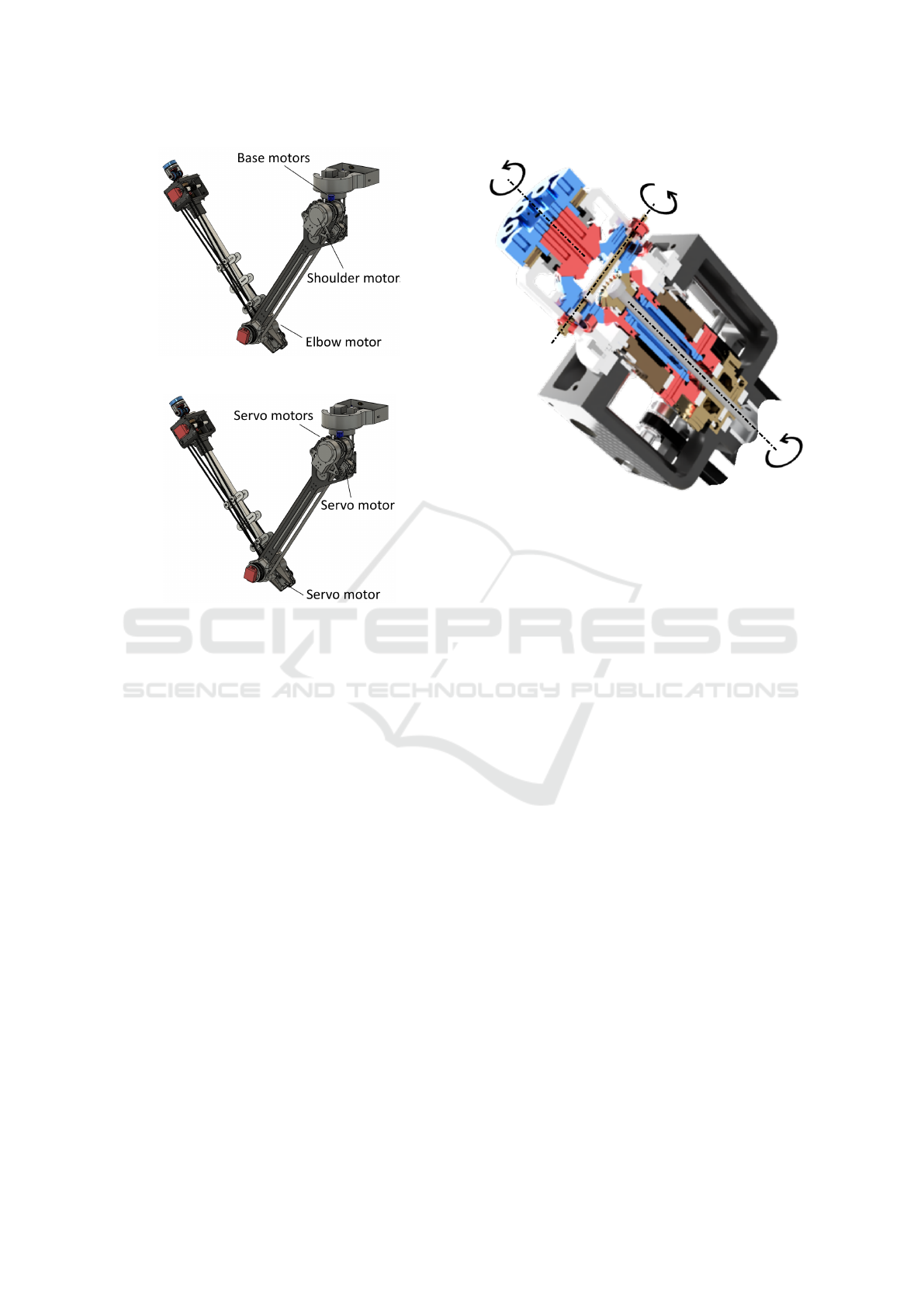
(a)
(b)
Figure 3: Motor disposition along the arm. (a) Brushless
motors for the arm, (b) servo motors for the wrist.
vide a comprehensive analysis, Table 1 compares the
proposed arm with these commercial robotic arms.
It is important to note that while the proposed arm
may have certain disadvantages in specific application
areas, it remains competitive, particularly in terms
of payload capacity. It is worth acknowledging that
the proposed solution competes favorably in the mar-
ket, despite being potentially disadvantaged in certain
comparison aspects due to the nature of its particular
application area. The focus on payload capacity is a
strength of the proposed arm, enabling it to excel in
tasks requiring substantial payload handling. In addi-
tion, the proposed solution is lighter (to be transported
from an aerial system) and the power requirement is
lower.
3.1 Mechanical Description
The arm has been designed considering two kinds of
motors, depending on the type of joint to control and
the demanded torque. In particular, the first three mo-
tors are brushless motors, while the spherical wrist is
composed of three servo motors (see Fig. 3). Also,
the actuation type depends on the positioning of the
motor along the arm structure and, in particular, the
Figure 4: Cad section of the spherical wrist design.
first joint is actuated directly by the motor, and the
link is attached to the motor’s output flange. The sec-
ond joint is actuated by the motor coupled with a har-
monic drive transmission to guarantee a reduction ra-
tio of 1:100. Finally, the third joint is actuated by the
motor coupled with a harmonic drive transmission to
guarantee a reduction ratio of 1:80, while it uses a
belt-pulley mechanism to actuate the forearm. During
the design process, the FEA (Finite Element Analy-
sis) has been conducted. Each part of the arm has
been designed with the same approach, using a first
layer forming the structure of the overall dimensions,
and a second layer made by a thin element realized
in strong material (carbon fiber or aluminum). This
provides structural resistance to the robot, while guar-
anteeing at the same time the required lightness. The
analysis demonstrated that carbon fiber layers work
properly, absorbing a great part of the stress. As for
the spherical wrist, it has been designed in steel and
a section is shown in Figure 4. The three wrist joints
are actuated using servomotors and belts.
3.2 Electrical Description
The power unit of the robotic arm is thoughtfully inte-
grated within the manipulator base, contributing to a
neat and self-contained system. To activate the arm, a
24 V power supply unit is required, providing the nec-
essary electrical energy. In terms of communication,
the arm establishes an Ethernet connection with an
external controller, typically a standard laptop. This
communication link allows for seamless interaction
and control of the arm’s operations. Further informa-
ICINCO 2023 - 20th International Conference on Informatics in Control, Automation and Robotics
468

Table 1: Comparison between commercial robot arms and the proposed solution.
Dexter HDI UR3e Proposed arm
Robot weight [kg] 6 11.2 3
Reach [mm] 700 500 700
Payload [kg] 3 3 5
Power requirements [W] 40 - 100 100 - 300 50
Joint ranges [deg] Base
Pivot
Shoulder
Differential
Differential
Gripper
360
270
270
180
360
300
Base
Shoulder
Wrist1
Wrist2
Wrist3
360
360
360
360
360
Base
Shoulder
Elbow
Wrist1
Wrist2
Wrist3
360
180
270
360
360
360
End effector included Yes No No
tion regarding the system architecture can be found in
Section 5.
The firmware implementation, responsible for di-
rectly controlling the hardware, is executed on an
on-board microcontroller. This microcontroller effi-
ciently handles communication with the motors and
sensors, ensuring accurate and real-time control of
the arm’s movements. To consolidate the electronic
components and optimize space utilization, a com-
pact custom-made Printed Circuit Board (PCB) is em-
ployed, providing a centralized platform for the nec-
essary electronics. Additionally, a fuse is incorpo-
rated into the system design to protect against short-
circuits, promptly interrupting the power supply in
such instances and safeguarding the overall system.
As previously mentioned, the arm has been de-
signed with versatility in mind, enabling it to work
with various tools and end-effectors. To facilitate ef-
fortless integration of these tools, their servomotors
can be easily connected in a daisy-chain configuration
to the wrist control motors. The microcontroller intel-
ligently detects and manages these connected tools,
allowing for seamless switching between different
tools during operation. This flexibility and modularity
enhance the arm’s adaptability to diverse task require-
ments.
Furthermore, the arm incorporates two Inertial
Measurement Units (IMUs), strategically placed on
the wrist and elbow. These IMUs provide valuable
data to the microcontroller, which utilizes it to com-
pensate for elasticity caused by the belts and the high
payload of the arm. By actively compensating for
elasticity, the arm achieves more precise and accu-
rate movements, ensuring optimal performance. For
a more comprehensive understanding of the elastic-
ity compensation method employed, refer to Section 4
for detailed information.
4 ELASTICITY COMPENSATION
As already stated, the utilization of belt transmis-
sions in the arm introduces inherent challenges related
to elasticity. While transient behavior can be toler-
ated due to the arm’s limited velocity, steady-state er-
rors may still occur. These errors become more pro-
nounced as the payload weight increases and the arm
extends further. Given that the proposed arm is specif-
ically designed for heavy tasks, such as manipulating
objects weighing up to 5 kg, it is imperative to address
this issue. Failure to do so can result in significant
displacement of the end effector caused by elasticity,
rendering it incapable of autonomously executing as-
signed motion tasks.
To tackle this problem, our solution incorporates
two IMUs strategically positioned on the wrist and el-
bow of the arm. These IMUs are installed at the end
of the second and third links of the arm, as depicted in
Figure 2 (a). By leveraging the data provided by these
IMUs, it becomes possible to accurately calculate the
real orientation of the arm’s links and the precise posi-
tion of the end effector. This information enables the
implementation of corrective measures, allowing the
arm to successfully execute tasks even in the presence
of elasticity.
Given that the arm motors are controlled in veloc-
ity, the computation of the commanded velocity for
the i-th motor is based on the desired position q
d,i
of
the i-th link and the current position q
m
i
measured by
the motor’s encoder.
v
d,i
= G
r,i
∗ K
p,i
∗ ˜q
i
(1)
where G
r,i
is the gear ratio of the transmission linked
to the motor i, K
p,i
is a proportional gain conveniently
tuned, and ˜q
i
= q
d,i
− q
m
i
is the error between the de-
sired link orientation and the orientation given by the
Design and Control of a Novel High Payload Light Arm for Heavy Aerial Manipulation Tasks
469

motor encoder also considering the mechanical trans-
mission.
Due to the elasticity, the real orientation q
i
of the
i-th link is different from the q
m
i
read by the motor’s
encoder. For this reason, there will be an error at
steady-state that the system is not aware of. Consider
now the value q
i
i
read by the IMU: this represents the
real orientation of the i-th link.
The equation of the commanded velocity be-
comes:
v
d,i
= G
r,i
∗ K
p,i
∗
˜
ˆq
i
(2)
where
˜
ˆq
i
= q
d,i
− q
i
i
is the error between the de-
sired orientation and the one read by the IMU. The
implementation of elasticity compensation, as previ-
ously described, is executed on the on-board micro-
controller and can be activated or deactivated through
commands sent by the main companion computer. By
adopting this approach, the correction algorithm re-
mains transparent to the high-level controller and tra-
jectory planner, allowing for seamless integration into
the overall system. The microcontroller takes charge
of establishing communication with the IMUs and ap-
plies a low-pass filter to the measurements obtained
from them. This filtering process helps to refine the
accuracy of the data used for elasticity compensation.
Additionally, a security layer is incorporated to han-
dle potential issues such as missing or noisy measure-
ments from the IMUs. If such situations occur, the se-
curity layer activates, halting the correction algorithm
and reverting back to the standard controller. This im-
plementation of elasticity compensation has proven to
be highly effective in mitigating the effects of elas-
ticity caused by high payloads. It ensures the arm
is capable of successfully accomplishing the required
tasks, as discussed in Section 6. By enabling precise
and reliable compensation, the arm can maintain the
desired trajectory and achieve the desired level of per-
formance.
5 SYSTEM ARCHITECTURE
This section provides an overview of the system archi-
tecture implemented to successfully control the arm.
The architecture comprises two main layers, each
serving a specific purpose, and is outlined in Figure 5.
The first layer consists of the Controllers, which
are implemented on an external companion com-
puter running a standard GNU/Linux operating sys-
tem. This layer leverages the Robot Operating Sys-
tem (ROS) (Joseph and Cacace, 2018) as the robotic
middleware. Within this layer, two distinct types
of controllers have been developed. The first con-
troller enables motion control in the arm’s joint space,
known as Direct Joint Control. It allows precise con-
trol over individual joints, facilitating intricate move-
ments. The second controller enables control of the
arm in the operational space, known as Inverse Ki-
netic Control. This controller utilizes the Kinematics
and Dynamics Library (KDL), enabling precise con-
trol of the arm’s position and orientation in the opera-
tional space.
At a lower level, the system hardware is controlled
by a custom firmware installed on a microcontroller.
This firmware is responsible for implementing the
communication protocol with the brushless and servo
motors used in the arm. Through this communication
protocol, the firmware allows commanding the posi-
tion and velocity of the motors, while retrieving their
current state as output. In addition to motor control,
this layer incorporates essential safety checks to en-
sure compliance with joint and velocity limits, pre-
venting any potential violations. Furthermore, this
layer includes a configuration storage system, which
stores a set of pre-planned configurations. These con-
figurations are utilized to set up the arm for different
operations, such as an initial manipulation configu-
ration or a closing transporting configuration. In ad-
dition, in this layer are implemented all the needed
value transformation to translate joint commands into
motor commands, taking into account gear rations
and motor coupling.
To establish communication between the compan-
ion computer and the microcontroller, a custom net-
work interface is employed. This network interface
utilizes an Ethernet connection, facilitating reliable
and efficient data transmission between the two com-
ponents of the system.
The hardware chosen for the development of the
mechatronic system is listed in the following.
• Three T-Motor motors Ak60 have been selected
for the first three elements of the arm. The com-
munication protocol has been implemented using
the CAN standard
• The spherical wrist is composed of Dynamixel
MX28-AT 2.0 servomotors, communicating with
the RS485 protocol
• The WitMotion WT61C inertial sensors have been
used for the elasticity compensation, with the TTL
communication protocol.
• The microcontroller connecting the compound
computer and the system hardware is based on the
ST STM32F767ZI microcontroller
ICINCO 2023 - 20th International Conference on Informatics in Control, Automation and Robotics
470
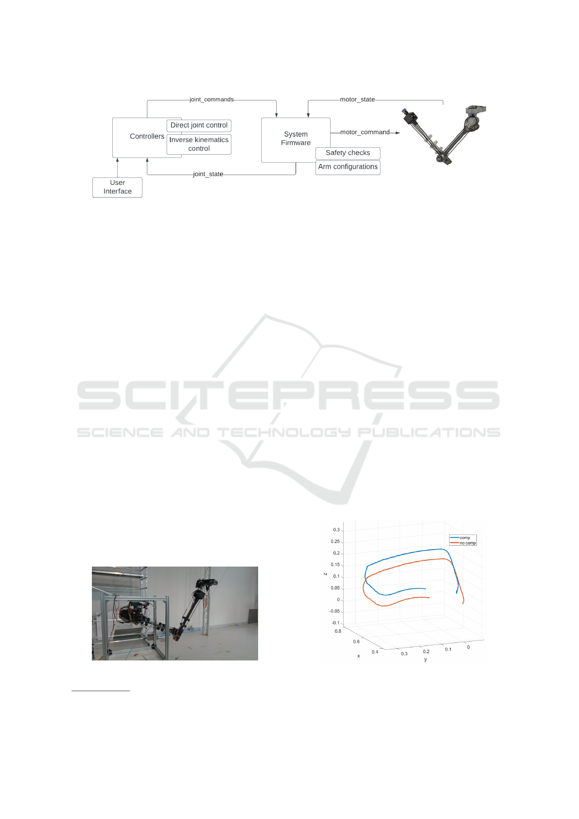
Figure 5: System architecture.
6 EXPERIMENTS
The system under examination has been tested in two
different operational scenarios, each providing differ-
ent insights into its performance and capabilities.
In the first case, the arm was subjected to testing
within a controlled indoor facility. This facility was
equipped with an OptiTrack
3
motion capture system,
used to accurately track the arm’s movements. By
employing this motion capture system, the position
of the manipulator’s end-effector relative to its base
throughout various motions has been tracked. As for
the second test case, the arm has been tested in a real-
world experiment. In this scenario, the arm was posi-
tioned downward in an aerial system that was perched
over a power line cable. This setup aimed to simu-
late a practical application where the arm needed to
be deployed in an elevated and potentially hazardous
environment.
A video showing the execution of those experi-
ments can be found at: http://y2u.be/vDPNLvIjPpo.
6.1 Case Study 1
In this particular test case, the robotic arm was firmly
secured to a stable ground structure to eliminate any
external factors that could affect its motion. To simu-
late a practical scenario, a device weighing 2 kg was
Figure 6: Laboratory site to test the proposed manipulator
in the elasticity compensation task.
3
https://optitrack.com/
attached to the end effector of the arm. This additional
payload introduces challenges related to elasticity and
requires effective compensation strategies to maintain
precise control.
To assess the performance of the control approach,
an operational space trajectory consisting of four
waypoints was planned. To ensure smooth and con-
tinuous motion, a fifth-order spline was used to in-
terpolate between the waypoints. The trajectory was
executed twice: once with the elasticity compensation
enabled and once without it. This comparative anal-
ysis enables a direct evaluation of the impact of the
compensation technique on the arm’s ability to accu-
rately follow the desired trajectory.
During the motion task, the OptiTrack motion
capture system was employed to track the position of
the end effector relative to the base frame of the arm.
This high-precision tracking system provides accurate
and reliable measurements of the arm’s actual motion.
The results of the motion capture system were
analyzed and compared between the two modalities,
with and without elasticity compensation. Figure 7
illustrates the recorded motion displacement, clearly
highlighting the differences between the compensated
and uncompensated motions. Notably, the z-axis,
Figure 7: Laboratory test using a motion capture system to
estimate the effect of the elasticity compensation during the
operations.
Design and Control of a Novel High Payload Light Arm for Heavy Aerial Manipulation Tasks
471

Figure 8: Real world experiment tests case: installation of a particular tool on a power line. (a) Approaching, (b) tool inserting,
(c) clamping, (d) releasing. A video of this process can be seen at http://y2u.be/vDPNLvIjPpo.
which is most affected by the presence of the attached
payload, exhibits a more significant displacement.
These detailed observations and comparisons pro-
vide valuable insights into the effectiveness of the
control approach, specifically in compensating for the
elasticity induced by the payload. By evaluating the
differences in motion between the two modalities, the
arm’s performance and the efficacy of the compensa-
tion strategy can be accurately assessed and validated.
6.2 Case Study 2
The second test case has been carried out in the
ATLAS Experimental Flight Center
4
located in the
Southern Spain. In this test, the aerial system is
perched on a power line cable, while the arm is used
to hold a recharging station on the same cable. This is
a representative task of the Aerial Core project and, in
particular, such a station is used to charge the batter-
ies of the UAV during the inspection operations, ex-
ploiting the electricity of the power grid. The weight
of the station is around 3.5 kg and consists of a bat-
tery charger and two clamps with a housing for the
power cable. In addition, the station is actuated in or-
der to close its clamps around the cable. The goal of
the aerial manipulator in this case, was to correctly
deploy the charger station on the power line. An ex-
ample of this process is depicted in Figure 8, where
the main steps of the task are depicted, from an initial
task configuration, to the installation of the device on
the cable.
7 CONCLUSIONS
This work introduces a novel design concept for
a lightweight manipulator specifically engineered to
handle heavy aerial manipulation tasks. One key fea-
4
https://atlascenter.aero/en/
ture of this design is the strategic placement of the
Center of Mass, situated as close as possible to the
arm base. This configuration enhances the arm’s
portability, making it well-suited for transportation
using flying systems.
The primary actuation mechanism employed in
this manipulator is based on a set of belts. How-
ever, this choice introduces challenges in achieving
precise motion at the tip of the manipulator due to
the inherent elasticity of the belt system. This behav-
ior becomes particularly prominent when the arm is
subjected to heavy payloads. To address this issue, a
control approach is proposed to mitigate the effects of
elasticity during arm motion. This approach, coupled
with the overall system design, aims to optimize the
arm’s performance and ensure accurate and reliable
manipulation tasks.
The main case study for evaluating the proposed
arm is within the domain of the Aerial Core EU
project. In this project, the aerial arm is specifically
employed for inspection and maintenance operations
of electrical power grids. This real-world application
showcases the practical significance and potential of
the proposed system in addressing critical infrastruc-
ture challenges.
To validate the effectiveness of the proposed sys-
tem, both laboratory tests and real-world experiments
have been conducted. These experiments include the
transportation of a 3.5 kg payload, demonstrating the
arm’s capability to handle substantial loads and per-
form precise operations. The results of these tests
highlight the system’s performance and its potential
impact in real-world scenarios.
Moving forward, the future direction of this work
involves an extensive evaluation of the arm’s capa-
bilities, focusing on more qualitative analysis. This
entails further investigations and assessments to com-
prehensively understand the arm’s performance char-
acteristics, enabling refinement and enhancement of
its capabilities for a wider range of applications.
ICINCO 2023 - 20th International Conference on Informatics in Control, Automation and Robotics
472

ACKNOWLEDGEMENTS
The research leading to these results has been sup-
ported by the AERIAL-CORE project (Horizon 2020
Grant Agreement No. 871479). The authors are
solely responsible for its content.
REFERENCES
Bellicoso, C. D., Buonocore, L. R., Lippiello, V., and Si-
ciliano, B. (2015). Design, modeling and control of a
5-dof light-weight robot arm for aerial manipulation.
In 2015 23rd Mediterranean Conference on Control
and Automation (MED), pages 853–858.
Cacace, J. and et al. (2021). Safe local aerial manipulation
for the installation of devices on power lines: Aerial-
core first year results and designs. Applied Sciences,
11(13).
Cacace, J., Finzi, A., Lippiello, V., Furci, M., Mimmo, N.,
and Marconi, L. (2016). A control architecture for
multiple drones operated via multimodal interaction
in search rescue mission. In 2016 IEEE International
Symposium on Safety, Security, and Rescue Robotics
(SSRR), pages 233–239.
Cacace, J., Finzi, A., Lippiello, V., Loianno, G., and San-
zone, D. (2013). Aerial service vehicles for indus-
trial inspection: Task decomposition and plan execu-
tion. In Ali, M., Bosse, T., Hindriks, K. V., Hoogen-
doorn, M., Jonker, C. M., and Treur, J., editors, Recent
Trends in Applied Artificial Intelligence, pages 302–
311, Berlin, Heidelberg. Springer Berlin Heidelberg.
Cacace, J., Giampetraglia, L., Ruggiero, F., and Lippiello,
V. (2023). A novel gripper prototype for helical bird
diverter manipulation. Drones, 7(1).
Cano, R., Perez, C., Prua
˜
no, F., Ollero, A., and Heredia, G.
(2014). Mechanical design of a 6-dof aerial manipu-
lator for assembling bar structures using uavs.
Chermprayong, P., Zhang, K., Xiao, F., and Kovac, M.
(2019). An integrated delta manipulator for aerial re-
pair: A new aerial robotic system. IEEE Robotics &
Automation Magazine, 26(1):54–66.
Franchi, A. (2019). Platforms with Multi-directional Total
Thrust, pages 53–65. Springer International Publish-
ing, Cham.
Hamaza, S., Georgilas, I., Fernandez, M., Sanchez, P.,
Richardson, T., Heredia, G., and Ollero, A. (2019).
Sensor installation and retrieval operations using an
unmanned aerial manipulator. IEEE Robotics and Au-
tomation Letters, 4(3):2793–2800.
IEEE (2009). Guide for maintenance methods on energized
power lines. Std 516-2009, pages 1–144.
Joseph, L. and Cacace, J. (2018). Mastering ROS for
Robotics Programming - Second Edition: Design,
Build, and Simulate Complex Robots Using the Robot
Operating System. Packt Publishing, 2nd edition.
Mishra, B., Garg, D., Narang, P., and Mishra, V. (2020).
Drone-surveillance for search and rescue in natural
disaster. Computer Communications, 156:1–10.
Miyazaki, R., Paul, H., Kominami, T., and Shimonomura,
K. (2020). Wire-suspended device control based
on wireless communication with multirotor for long
reach-aerial manipulation. IEEE Access, 8:172096–
172104.
Ollero, A., Tognon, M., Suarez, A., Lee, D., and Franchi,
A. (2022). Past, present, and future of aerial
robotic manipulators. IEEE Transactions on Robotics,
38(1):626–645.
Paul, H., Miyazaki, R., Ladig, R., and Shimonomura, K.
(2019). Landing of a multirotor aerial vehicle on an
uneven surface using multiple on-board manipulators.
In 2019 IEEE/RSJ International Conference on Intel-
ligent Robots and Systems (IROS), pages 1926–1933.
Ruggiero, F., Lippiello, V., and Ollero, A. (2018). Aerial
manipulation: A literature review. IEEE Robotics and
Automation Letters, 3(3):1957–1964.
Shimahara, S., Leewiwatwong, S., Ladig, R., and Shimono-
mura, K. (2016). Aerial torsional manipulation em-
ploying multi-rotor flying robot. In 2016 IEEE/RSJ
International Conference on Intelligent Robots and
Systems (IROS), pages 1595–1600.
Sibanyoni, S. V., Ramotsoela, D. T., Silva, B. J., and
Hancke, G. P. (2019). A 2-d acoustic source localiza-
tion system for drones in search and rescue missions.
IEEE Sensors Journal, 19(1):332–341.
Suarez, A., Heredia, G., and Ollero, A. (2018). Design of
an anthropomorphic, compliant, and lightweight dual
arm for aerial manipulation. IEEE Access, 6:29173–
29189.
Suarez, A., Nekoo, S. R., and Ollero, A. (2023). Ultra-
lightweight anthropomorphic dual-arm rolling robot
for dexterous manipulation tasks on linear infras-
tructures: A self-stabilizing system. Mechatronics,
94:103021.
Suarez, A., Real, F., Vega, V. M., Heredia, G., Rodriguez-
Casta
˜
no, A., and Ollero, A. (2020). Compliant bi-
manual aerial manipulation: Standard and long reach
configurations. IEEE Access, 8:88844–88865.
Tognon, M., Ch
´
avez, H. A. T., Gasparin, E., Sabl
´
e, Q.,
Bicego, D., Mallet, A., Lany, M., Santi, G., Re-
vaz, B., Cort
´
es, J., and Franchi, A. (2019). A truly-
redundant aerial manipulator system with application
to push-and-slide inspection in industrial plants. IEEE
Robotics and Automation Letters, 4(2):1846–1851.
Tosato, P., Facinelli, D., Prada, M., Gemma, L., Rossi, M.,
and Brunelli, D. (2019). An autonomous swarm of
drones for industrial gas sensing applications. In 2019
IEEE 20th International Symposium on ”A World of
Wireless, Mobile and Multimedia Networks” (WoW-
MoM), pages 1–6.
Trujillo, M. A., Martinez-de Dios, J. R., Martin, C., Vig-
uria, A., and Ollero, A. (2019). Novel aerial manip-
ulator for accurate and robust industrial ndt contact
inspection: A new tool for the oil and gas inspection
industry. Sensors, 19(6).
Uzakov, T., Nascimento, T. P., and Saska, M. (2020). Uav
vision-based nonlinear formation control applied to
inspection of electrical power lines. In 2020 Inter-
national Conference on Unmanned Aircraft Systems
(ICUAS), pages 1301–1308.
Design and Control of a Novel High Payload Light Arm for Heavy Aerial Manipulation Tasks
473
