
Neural-Network for Position Estimation of a Cable-Suspended Payload
Using Inertial Quadrotor Sensing
Julien Mellet
a
, Jonathan Cacace
b
, Fabio Ruggiero
c
and Vincenzo Lippiello
d
PRISMA Lab, Department of Electrical Engineering and Information Technology, University of Naples Federico II,
Via Claudio 21, 80125, Naples, Italy
Keywords:
Neural Network, State Estimation, Quadrotor, Cable Suspended Payload.
Abstract:
This paper considers a standard quadrotor drone with a cable-suspended payload and minimal sensor config-
uration. A neural network estimator is proposed to perform accurate real-time payload position estimation. A
novel proprioceptive feedback measurement method is proposed, and a neural network has been trained with
domain randomization. The network shows accurate zero-shot estimation, even with excitations never seen
by the system before. This preliminary work has been tested in a simulated environment and aims to show
that only onboard inertial sensing is enough to achieve the sought task. The presented work may open new
applications for drone transportation in real environments subject to several perturbations.
1 INTRODUCTION
For aerial vehicles, there is a weight obsession such
that, especially for transportation tasks, each saved
gram on the platform is a gram for the payload (An-
derson and Gaston, 2013). Thanks to its simplicity,
a cable-suspended payload under an aerial vehicle re-
mains an elegant way to move any object through the
air (see Fig. 1). Compared to a mechatronic arm,
this system is lightweight and easy to install, uti-
lizing a single passive cable fixation point. (Suarez
et al., 2020). Despite new aerial platforms like om-
nidirectional drones, quadrotors have demonstrated a
decade-long reliability (Bodie et al., 2019). A quadro-
tor with suspended load is comparable to helicopters
achieving object transport but with a difference in
agility and sensory system (Wendel et al., 2006). Nev-
ertheless, research tends to increase flight accuracy by
embedding as many sensors as possible at the expense
of lightness and agility (Lanegger et al., 2 06), (Panet-
sos et al., 2022).
This preliminary study presents an approach that
simplifies suspended payload position estimation in a
standard quadrotor, eliminating the need for extero-
ceptive sensor processing. Hence, only internal state
a
https://orcid.org/0009-0007-8386-0012
b
https://orcid.org/0000-0002-1639-5655
c
https://orcid.org/0000-0001-7539-9157
d
https://orcid.org/0000-0002-6089-2333
Figure 1: Pick and place tasks of the cable-suspended sys-
tem. In the first frame, the drone reaches the package. The
grasp of the payload is done in the second frame. From
frame three to six, the load is transported. The last frame
shows the packet’s release, which is dropped into its target
location.
configuration at a high temporal rate is employed in-
stead of cameras or any position sensor. Such sys-
tems are robust to environmental variations. The dis-
turbances induced by the payload on the system are
used to let a specially trained network find a corre-
lation with the payload position. To the best of the
authors’ knowledge, no prior work achieved such ac-
curacy in estimating suspended payload position in
minimal aerial transportation setups.
1.1 Related Works
Conventional approaches to cable-suspended pay-
load transportation use external sensors such as cam-
80
Mellet, J., Cacace, J., Ruggiero, F. and Lippiello, V.
Neural-Network for Position Estimation of a Cable-Suspended Payload Using Inertial Quadrotor Sensing.
DOI: 10.5220/0012204100003543
In Proceedings of the 20th International Conference on Informatics in Control, Automation and Robotics (ICINCO 2023) - Volume 1, pages 80-87
ISBN: 978-989-758-670-5; ISSN: 2184-2809
Copyright © 2023 by SCITEPRESS – Science and Technology Publications, Lda. Under CC license (CC BY-NC-ND 4.0)

era (Tang et al., 2018), (Guo and Leang, 2020). Get-
ting a direct measurement of the payload position is
a reasonable option. Even with a relatively low mea-
surement rate compared to the low-level controller, it
allows making aggressive flights (Tang et al., 2018).
However, cameras suffer from several problems like
brightness (close to shadow), flickering (while flying
over the sea), or fogging (in a humid area), making
their use standalone unsafe for reliable industrial ap-
plications. The issue has also been revealed by (Lee
and Kim, 2017), where the proposed solution con-
sists of adding force sensors to the system. Equiva-
lent sensing solutions have been adopted by (Lv et al.,
2021), with the addition of a universal joint between
the drone and the cable for the second one. Recently,
(Panetsos et al., 2022) used four different sensors to
get accurate cable state estimation, while (Outeiro
et al., 2023) proposed an adaptive geometric control
method with asymptotic tracking stability.
A similar approach to ours is described by (Kauf-
mann et al., 2020) and (Cioffi et al., 2022) to perform
agile maneuvers. The use of internal sensing in those
papers is called sensorimotor, but for the unification
of the terms in robotics, we will call it proprioception,
like it has been done in (Lee et al., 2020). Even if we
do not have access to direct measurement of the motor
speed, the PWM (Pulse-Width Modulation) command
gives a fair proportional estimation. A neural network
(NN) is implemented to control the drone. In partic-
ular, the work done by (Cioffi et al., 2022) learns in-
ertial odometry and gets accurate position estimation
without using any visual perception. However, the
positioning tracking has been done with previously
known trajectories. In contrast, for safety reasons, we
implemented a neural network trained by supervised
learning on the estimation stage of the tethered pay-
load controller.
One of the most advanced research on payload
state estimation using quadrotor proprioception is for
parameter estimation (Prka
ˇ
cin et al., 2020). Re-
cently, such a work has been improved by (Prka
ˇ
cin
et al., 2021) with the implementation of an extended
Kalman filter (EKF). However, estimation of load pa-
rameters remains challenging with the employed fast
Fourier transform technique, getting only off-line re-
sults. Unfortunately, even if the research looks in an
interesting direction with a minimal drone setup, real-
time performance has not been reached. Real-world
experiments showed poor results in tracking the an-
gles of the payload. The system is non-linear, and
the IMU is noisy while drones fly at high velocity.
This makes classical EKF implementation unusable
for real flights application. To tackle real-time, we use
the concept of a neural observer (Chen et al., 2018)
with a recurrent NN to access indirectly measured
data (Habtom and Litz, 1997).
1.2 Contribution
In this paper, we prove the feasibility of real-time
position estimation of a cable-suspended end-effector
using only inertia sensors onboard a standard quadro-
tor. Contrary to the classic EKF approach, our method
does not need to define any parameter a priori. We
used a supervised learned network, making the posi-
tion estimation of the suspended load for a standard
quadrotor attitude controller. The neural estimator is
trained in a simulated environment, with domain ran-
domization, and runs the software controller in the
loop. We reached zero-shot generalization of the net-
work for load position estimation. After being trained
on our dataset, the network has the capability to pre-
dict previously unseen perturbations, in particular, di-
rect injection of energy into the end-effector. This
shows the consistency of the estimator implementa-
tion, as well as its generalization capabilities.
2 MATERIALS AND METHODS
Making payload pose estimation is not a trivial task,
and the classical filter approach showed accuracy lim-
itations (Prka
ˇ
cin et al., 2021). In this section, we first
define our model, which is needed for the simulation,
and implement an attitude controller. Then, we focus
on data processing to measure our features to train
the network. Finally, to smooth the training, we grad-
ually increase the measurement domain exploration
with progressively more sophisticated trajectories.
2.1 Model
For the quadrotor, we consider the dynamic model
with the Euler angles (Ollero and Siciliano, 2019).
Here we use FLU (Front-Left-Up) convention to de-
fine the body frame B with axes {x, y, z}, and the
world frame W with axes {x
w
, y
w
, z
w
}. We define the
drone position and its attitude as p
b
= [x
b
, y
b
, z
b
]
⊤
∈
R
3
and η
b
= [φ
b
, θ
b
, ψ
b
]
⊤
∈ R
3
, respectively, with
their time derivatives ˙p
b
and
˙
η
b
. The attitude can also
be defined with R
b
∈ SO(3), the rotation matrix from
B to W , the special orthogonal group of dimension
three, from which the roll-pitch-yaw angles φ
b
, θ
b
,
and ψ
b
, respectively, can be extracted. These give the
linear and angular accelerations of the base as,
¨p
b
= g e
3
+
1
m
u
T
R
b
e
3
, (1)
Neural-Network for Position Estimation of a Cable-Suspended Payload Using Inertial Quadrotor Sensing
81

Payload
position
controller
Payload
attitude
controller
Quadrotor
attitude
controller
Plant
quadrotor &
payload
Neural
estimator
𝜼
𝒃
, 𝝎
𝒃
𝒃
𝒇
𝒖
, 𝝉
𝒖
𝒖
𝑻
, 𝜼
𝒃,𝒅
𝒑
𝒍
, 𝒑
𝒍
̇
𝒒
𝒍
, 𝒒
𝒍
̇
𝒒
𝒍,𝒅
𝒑
𝒃
̈
, 𝜼
𝒃
̇
, 𝝎
𝒑
𝒍,𝒅
, 𝒑
𝒍,𝒅
̇
Figure 2: Control layout architecture with neural network state estimation.
Figure 3: Schematic representation of the quadrotor (in
blue) with the cable-suspended payload (in red). The terms
l
s
, l
c
∈ R, with l
c
>> l
s
are the support length and the cable
length, respectively. Besides, ω
i
∈ R, i = 1, . .. , 4 are the ro-
tation speed of the motors, while θ
1
, θ
2
∈ R are the angles
of the cable with respect to the drone.
¨
η
b
= M(η
b
)
−1
(−C(η
b
,
˙
η
b
) + Q
⊤
(η
b
)τ
b
), (2)
where g ∈ R is the gravity, m ∈ R is the drone
mass, and e
3
= [0, 0, 1]
⊤
. Moreover, M(η
b
) =
Q(η
b
)
⊤
I
b
Q(η
b
) ∈ R
3×3
is the symmetric and posi-
tive definite (provided that θ ̸= ±
π
2
) mass matrix, I
b
∈
R
3×3
is the drone inertia matrix, and Q(η
b
) ∈ R
3×3
is the transformation matrix such that ω
b
b
= Q(η
b
)
˙
η
b
,
where ω
b
b
∈ R
3
is the angular velocity of the B with
respect to the W expressed in B. Finally, C(η
b
,
˙
η
b
) =
Q
⊤
(η
b
)S(Q(η
b
)
˙
η
b
)I
b
Q(η
b
)+Q
⊤
(η
b
)
⊤
I
b
˙
Q(η
b
) ∈ R
3
is the Coriolis matrix, with S(·) ∈ R
3×3
the skew-
symmetric operator, τ
b
= [τ
x
, τ
y
, τ
z
]
⊤
∈ R
3
is the
torque control vector, and u
T
∈ R
+
is the total thrust.
The physical control inputs to the system, that is
the propeller velocities ω
i
∈ R, with i = 1, . . . , 4 (see
Fig. 3), can be retrieved from the torques and the total
thrust through the allocation matrix as follows,
u
T
τ
x
τ
y
τ
z
=
c
T
c
T
c
T
c
T
0 lc
T
0 −lc
T
−lc
T
0 lc
T
0
−c
Q
c
Q
−c
Q
c
Q
ω
2
1
ω
2
2
ω
2
3
ω
2
4
, (3)
where c
T
, c
Q
∈ R
+
are the thrust constant and drag
factor, respectively.
For the suspended-cable, several models were pro-
posed in the literature, such as finite element approx-
imation (Goodarzi et al., 2014), elastic rope (Kotaru
et al., 2017), or a rigid bar (Tang et al., 2018). The
last model has been chosen for ease of simulation.
It represents the most interesting case for transporta-
tion. Details of the model are presented by (Sreenath
et al., 2013) and explained in Fig. 3. Recall that
the quadrotor is a differentially flat system (Rathi-
nam et al., 1995), while the quadrotor with a cable-
suspended payload is a differentially flat hybrid sys-
tem (Tang et al., 2018; Sreenath et al., 2013). Hence,
all state and input variables are defined through non-
linear equations involving flat variables and their re-
spective derivatives.
The load is considered as a point mass, the mass
of the cable is neglected, and the cable is considered
rigid. The variables are defined in Fig. 3. The position
of the quadrotor in W can be retrieved from the load
position as
p
b
= q
l
− l
c
p
l
, (4)
where q
l
∈ R
3
is the load position in W and p
l
∈ S
2
,
with S
2
the manifold of unit vectors in R
3
, is the unit
vector pointing the load from the quadrotor’s center
of mass.
2.2 Control
The controller presented by (Sreenath et al., 2013)
and applied by (Tang et al., 2018) is here briefly
reported. The state and input are defined as, x =
[p
⊤
l
, ˙p
⊤
l
, p
⊤
b
, ˙p
⊤
b
,
˙
η
⊤
b
, ω
b
⊤
b
]
⊤
and u = [ f
⊤
u
, τ
⊤
u
]
⊤
, re-
spectively.
First, define the low level quadrotor attitude con-
troller as,
τ
b
= −K
R
e
R
− K
ω
e
ω
+ S(ω
b
b
)I
b
ω
b
b
−I
b
(S(ω
b
b
)R
⊤
b
R
b,d
ω
b,d
b,d
− R
⊤
b
R
b,d
˙
ω
b,d
b,d
),
(5)
where K
R
, K
ω
∈ R
3×3
are diagonal gain matrices,
e
R
=
1
2
(R
⊤
b,d
R
b
− R
⊤
b
R
b,d
)
∨
∈ R
3
is the quadrotor at-
titude error, e
ω
= ω
b
b
− R
⊤
b
R
b,d
ω
b,d
b,d
∈ R
3
is the an-
gular velocity error, (·)
∨
is the vee operator mapping
a skew-symmetric matrix into the vector that gener-
ated it, R
b,d
∈ SO(3) is the desired quadrotor rotation
matrix, ω
b,d
b,d
∈ R
3
is the desired angular velocity ex-
pressed in the desired body frame.
The desired R
b,d
and ω
b,d
b,d
are retrieved from the
position controller as explained by (Tang et al., 2018).
ICINCO 2023 - 20th International Conference on Informatics in Control, Automation and Robotics
82

Features Recurrent Net MLP Labels
IMU
(accelerometer + gyroscope)
𝒑
𝒃
̈
Control Input
(thrust + attitude)
Motors Speed
𝜼
𝒃
̇
𝝎
𝒖
𝑻
𝜼
𝒃,𝒅
1×14
8×256
⁝
1×128 1×64
⁝
⁝
𝟐
𝟏
1×2
𝟏
𝑥
𝑦
𝑧
𝑝
𝟐
𝑦
𝑧
𝑥
𝑝
𝟏
Cable
Angles
Figure 4: Neural network architecture. The NN keeps the history of the past data at the same rate. All features are processed
through a recurrent neural network layer. Then data are processed with a fully connected multi-layer perception before getting
the two angles of the cable.
The thrust input results from,
f
u
= u
T
R
b
e
3
, (6)
where,
u
T
= K
p
e
p
+ K
˙p
e
˙p
+ K
i
Z
e
p
dt, (7)
with K
p
, K
˙p
, K
i
∈ R
3
some diagonal and positive def-
inite gain matrices, e
p
= S(p
l
)
2
p
l,d
the error function
with p
l,d
∈ R
3
the desired load position in W , and
e
˙p
= ˙p
l
− S(S(p
l,d
) ˙p
l,d
)p
l
the time derivative. Then,
the desired quadrotor attitude is,
R
b,d
=
S
S(b)c
∥S(b)c∥
b,
S(b)c
∥S(b)c∥
, c
, (8)
with ∥ · ∥ the Euclidean norm, b =
u
T
∥u
T
∥
∈ R, and
c = [cos(ψ
b
), sin(ψ
b
), 0]
⊤
∈ R
3
.
Finally the payload position controller is defined
as,
q
l,d
= K
q
e
q
+ K
˙q
e
˙q
+ K
q,i
Z
e
q
dt, (9)
with K
q
, K
˙q
, K
q,i
∈ R
3
some diagonal and positive def-
inite gain matrices, e
q
= q
l
− q
l,d
∈ R
3
the error func-
tion, and e
˙q
= ˙q
l
− ˙q
l,d
∈ R
3
its time derivative.
The controller implementation is presented in
Fig. 2 and the NN estimator is explained in the next
section.
2.3 Neural Estimation
Through all the data provided by the IMU, the mag-
netometer has been found to add too much noise and
randomness to the result. Then, only the accelerome-
ter and the gyroscope are used.
Compared to (Kaufmann et al., 2020), we found
that sampling measurements with synchronization of
all the features were getting accurate results. Normal-
ization is done with min-max normalization. Assum-
ing X ∈ R a scalar, we use the unit-based normaliza-
tion,
X
norm
=
X −X
min
X
max
− X
min
. (10)
To avoid any overshoot on measurements X
meas
∈ R,
boundaries limits are fixed with saturation values such
that,
X
meas
∈ [X
min
, X
max
]. (11)
The main network architecture Fig. 4 remains con-
densed, with relatively few hidden layers. Keeping
the network as small as possible is to implement it on
a small computational unit and reduce the processing
latency. It has three incoming features branches with
the IMU ( ¨p
b
,
˙
η
b
) ∈ R
6
the motor speeds ω ∈ R
4
, and
the control inputs (u
T
, η
b,d
) ∈ R
4
. There is a total of
fourteen scalar input features [ ¨p
b
,
˙
η
b
, ω, u
T
, η
b,d
] pre-
processed as mentioned above.
For a later comparison study, we want to com-
pare different promising NNs, namely, a time convo-
lutional network (TCN) and two recurrent neural net-
works (RNN). For both cases, networks are trained on
a history of N time past steps to the current measure-
ment that are defined later. Even if TCN proved its
efficiency in neural estimation for drones (Kaufmann
et al., 2020; Cioffi et al., 2022), RNN looks to be a
more appropriate option. These layers take advan-
tage of processing sequential data to make the predic-
tion. In this study, we used Long Short-Term Mem-
ory (Hochreiter and Schmidhuber, 1997) (LSTM)
hidden neurons that have also been used by (Perin-
gal et al., 2022; Jung et al., 2022). We can notice that
simple RNN and gated recurrent unit (GRU) have also
been tested during this research, but the results were
similar to LSTM with poorer prediction accuracy. For
this reason, LSTM is the chosen recurrent net archi-
tecture.
The recurrent network trained with N = 15 times-
tamps of the past proprioceptive measurements fol-
lows. Even if the eight past measures were used
by (Kaufmann et al., 2020), we got better perfor-
mance with fifteen. Then, two fully connected layers
of MLPs give the cable angles (θ
1
, θ
2
). We use differ-
entiation to obtain the angular velocity ˙p
l
needed for
the controller in Fig. 2.
Neural-Network for Position Estimation of a Cable-Suspended Payload Using Inertial Quadrotor Sensing
83

Figure 5: Sample trajectories used to train networks. From left to right, with trajectories getting more complex through the
training: 1 min horizontal circle trajectory; 1 min vertical circle trajectory; 1 min horizontal lemniscate trajectory; 1 min
vertical lemniscate trajectory; 2 min of manual control.
2.4 Training
Compared to (Lee et al., 2020), (Faust et al., 2017)
that substantially used reinforcement learning to train
their networks, we used supervised learning. How-
ever, we kept the principle of accelerating the train-
ing with a given policy. Thus, we proposed to begin
the training with simple trajectories, letting the loss
converge smoothly. Then, we complicated the trajec-
tories to finish with erratic movements. Here, only
state estimation is performed by the network. The ad-
vantage of virtual training, is to have an infinite flight
time with variable parameters. The payload position
controller is fed with circular, lemniscate, and random
manual trajectories (see Fig. 5).
We trained the NN estimator through ten datasets
with the five different trajectories, depicted in Fig. 5,
and two different payloads of 200 g and 800 g. The
sum of the datasets gives a total of 140.10
3
times-
tamped measurements for 50 min flight time. We split
each trajectory dataset in two, with 20% for validation
and the remaining 80% for training.
To predict the load position, p
l
, a time window
of size 16 has been used. Thanks to the 15 past mea-
sured features, the 16
th
label is predicted. Because the
regressive network has to keep consistency through
time, no data shuffle was made. Nevertheless, each
data set was split up into batches of size 256. Trying
different batch sizes, it turned out this last was a good
trade-off. For the simulation, we used Gazebo, a sim-
ulator with a physic engine (Smith, 2008). The pro-
pellers’ drag, lift coefficients and IMU characteristics
are simulated through the internal plugin. We simu-
late our quadcopter with a stick with a two-degree-
of-freedom (DoF) universal joint, presented in Fig. 3.
Compared to real flights, the simulator does not pro-
vide any aerodynamic effects. As a result, the pay-
load is static under the drone while hovering. We then
propose to make domain randomization through the
excitation of the end-effector. It consists in applying
a relatively small bounded random force on the end-
effector. In our case, we selected a maximum force of
0.2 N. It is now about comparing the network’s per-
formances.
Table 1: Architectures of the three networks that are com-
pared for the study. LSTM2 with two recurrent layers and
an MLP before the output. TCN with a convolutional layer
followed by an MLP. LSTM embedding a unique recurrent
layer and two MLPs.
LSTM2 TCN LSTM
Hidden
layer 1
LSTM 256 Conv LSTM 256
Hidden
layer 2
LSTM 128 MLP 128 MLP 128
Hidden
layer 3
MLP 64 X MLP 64
2.5 Networks Comparisons
The first set of experiments compares the accuracy in
the prediction of three promising neural architectures.
Table 1 compares the architectures of the three net-
works used for the research. with two recurrent layers
and an MLP before the output. TCN with a convo-
lutional layer followed by an MLP. LSTM embeds a
unique recurrent layer and two MLPs. Then, the train-
ing through the different trajectories is presented in
Fig. 6.
Figure 6: Validation loss after training on each trajectory
dataset. From left to right, 1 corresponds to the horizontal
circle, 2 corresponds to the vertical circle, 3 corresponds
to the horizontal lemniscate, 4 corresponds to the vertical
lemniscate, and 5 corresponds to manual control.
One can notice that the validation loss decreases
after each trajectory train. This points out the im-
provement of the estimation prediction with more and
ICINCO 2023 - 20th International Conference on Informatics in Control, Automation and Robotics
84
more sophisticated trajectories. Nevertheless, even if
TCN showed a better accuracy on the validation set,
RNN performs better with the test set (see Fig. 7).
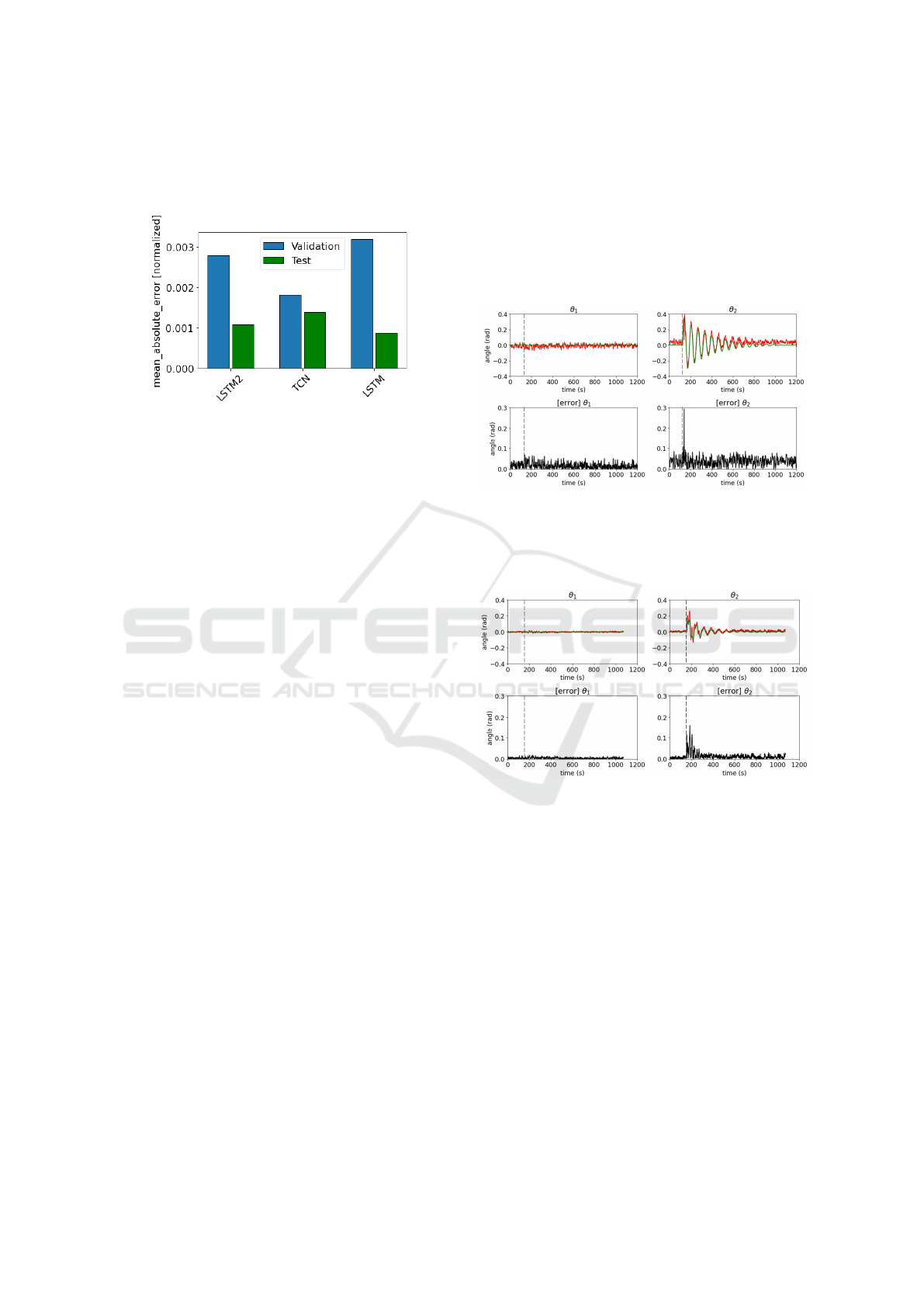
Figure 7: Mean absolute error of LSTM2, TCN, and LSTM
after being trained on the different datasets.
The better performance of TCN in Fig. 7 is notice-
able on the validation set, while LSTM is more accu-
rate on the test set. LSTM2 and even more LSTM has
thus a generalization capability. Both temporal con-
volution and recurrent networks result in the same or-
der of magnitude, thanks to temporal measurements.
The following section uses only LSTM to under-
stand what implies the change in payload mass on the
NN estimator.
3 APPLICATIONS
NN estimation takes a certain time to process. We
made an inference model of our network to accelerate
pose estimation during the experiments. We improved
the pose estimation processing from a mean response
time of 4.10
−2
s to an instant estimation of 10
−4
s
without losing accuracy.
3.1 Response to External Perturbations
Because the weight of the payload directly impacts
drone perturbation, and by implication the inertial
sensor measurements, we want to understand how the
weight impacts pose estimation of the end-effector.
To measure the accuracy of prediction, we have per-
turbed the load on the single x-axis with 40 N for the
200 g load (see Fig. 8) and with 100 N for the 800 g
load (see Fig. 9).
For both plots, with light-weight (see Fig. 8) and
heavy payload (Fig. 9), we notice that the estimation
follows the ground truth through time with a drop in
accuracy at the perturbation. Moreover, no perturba-
tion is measured on θ
1
, the non-perturbed axis, show-
ing the independence of each angle estimation.
Another critical point is the noise reduction in
payload state estimation with a heavier load. This
phenomenon should be explained for two reasons:
firstly, because the heavier load, with greater iner-
tia, have slower dynamics, which is easier to predict;
secondly, because the perturbation of the largest mass
has more effect on the system and disturbance can be
measured with higher intensity by the inertial unit.
Figure 8: Cable orientation estimation for a 200 g load and
40 N force excitation. The mean absolute error (MAE)
between ground-truth in green and estimated angle in red,
has been measured at 0.05326 rad. Perturbation is done at
t = 126 s.
Figure 9: Cable orientation estimation for a 800 g load and
100 N force excitation. The mean absolute error (MAE)
between ground-truth in green and estimated angle in red,
has been measured at 0.01772 rad. Perturbation is done at
t = 155 s.
3.2 Use Case Example
The proposed estimator was then applied in a pick-
and-place scenario. The idea is to understand the esti-
mation performance without training the network for
this specific application. The drone picks up a 600 g
package and transports it to a basket at the target lo-
cation. Figure 1 presents the environment in which
the system is used. The drone flies at a relatively slow
speed, keeping the near-hovering assumption.
Compared to the system subjected to simple dis-
turbances (see Figs. 8-9), we can notice a more sig-
nificant mean absolute error (MAE) during the entire
task in Fig. 10. The same comments as previously can
Neural-Network for Position Estimation of a Cable-Suspended Payload Using Inertial Quadrotor Sensing
85

Figure 10: Cable orientation estimation during a pick and
place task. The payload is grasped at t = 580 s, and released
at t = 1310 s. The mean absolute error (MAE) between
ground-truth in green and estimated angle in red, has been
measured at 0.08365 rad.
be made, on the influence of weight on estimation.
For θ
1
, MAE is more significant with the unloaded
end-effector, while precision increases with the pay-
load transported. An estimation bias has to be noticed
for θ
2
during the carriage. Likewise, the grasping ac-
tion being similar to a prompt perturbation, the same
result is observed as above, with a drop in accuracy.
In contrast to the grab, the release is smoother, and
the accuracy of the estimate changes from a lower to
a higher MAE.
4 CONCLUSION AND FUTURE
WORK
This preliminary study demonstrates that inertial
measurements are sufficient for estimating payload
position in cable-suspended drone systems, enabling
their integration into the controller. Moreover, in-
direct neural pose estimation has been proven ac-
curate in performing stable transportation tasks near
hovering. The hardware complexity has thus de-
creased. This estimator suits cable-suspended under-
water transport, free from sun reflection flickering on
water waves.
Future work will focus on transferring the NN
from simulation to reality thanks to domain random-
ization presented in this paper. The core idea is to test
the neural estimator in challenging-to-simulate envi-
ronments. On the other hand, we would like to take
advantage of this estimator to perform aggressive ma-
neuvers implementing model predictive control.
ACKNOWLEDGEMENTS
The research leading to these results has been sup-
ported by the AERIAL-CORE project (Horizon 2020
Grant Agreement No. 871479) and by the AERO-
TRAIN Project, European Union’s Horizon 2020
Research and Innovation Program under the Marie
Skłodowska-Curie Grant Agreement 953454. The au-
thors are solely responsible for its content.
REFERENCES
Anderson, K. and Gaston, K. J. (2013). Lightweight un-
manned aerial vehicles will revolutionize spatial ecol-
ogy. Frontiers in Ecology and the Environment,
11(3):138–146.
Bodie, K., Brunner, M., Pantic, M., Walser, S., Pfndler,
P., Angst, U., Siegwart, R., and Nieto, J. (2019).
An Omnidirectional Aerial Manipulation Platform for
Contact-Based Inspection. In Robotics: Science and
Systems XV. Robotics: Science and Systems Founda-
tion.
Chen, B., Zhang, H., Liu, X., and Lin, C. (2018). Neural
Observer and Adaptive Neural Control Design for a
Class of Nonlinear Systems. IEEE Transactions on
Neural Networks and Learning Systems, 29(9):4261–
4271.
Cioffi, G., Bauersfeld, L., Kaufmann, E., and Scara-
muzza, D. (2022). Learned Inertial Odometry for Au-
tonomous Drone Racing.
Faust, A., Palunko, I., Cruz, P., Fierro, R., and Tapia,
L. (2017). Automated aerial suspended cargo de-
livery through reinforcement learning. Artificial In-
telligence, 247:381–398. Special Issue on AI and
Robotics.
Goodarzi, F. A., Lee, D., and Lee, T. (2014). Geometric
stabilization of a quadrotor UAV with a payload con-
nected by flexible cable. In 2014 American Control
Conference, pages 4925–4930.
Guo, D. and Leang, K. K. (2020). Image-Based Estimation,
Planning, and Control of a Cable-Suspended Payload
for Package Delivery. IEEE Robotics and Automation
Letters, 5(2):2698–2705.
Habtom, R. and Litz, L. (1997). Estimation of unmea-
sured inputs using recurrent neural networks and the
extended Kalman filter. In Proceedings of Interna-
tional Conference on Neural Networks (ICNN’97),
volume 4, pages 2067–2071 vol.4.
Hochreiter, S. and Schmidhuber, J. (1997). Long Short-
Term Memory. Neural Comput., 9(8):1735–1780.
Jung, J., You, S., Kim, D., and Park, J. (2022). Vari-
able Stiffness Control via External Torque Estimation
Using LSTM. In 2022 International Conference on
Robotics and Automation (ICRA), pages 8325–8330.
Kaufmann, E., Loquercio, A., Ranftl, R., M
¨
uller, M.,
Koltun, V., and Scaramuzza, D. (2020). Deep Drone
Acrobatics.
ICINCO 2023 - 20th International Conference on Informatics in Control, Automation and Robotics
86

Kotaru, P., Wu, G., and Sreenath, K. (2017). Dynamics
and control of a quadrotor with a payload suspended
through an elastic cable. In 2017 American Control
Conference (ACC), pages 3906–3913.
Lanegger, C., Ruggia, M., Tognon, M., Ott, L., and Sieg-
wart, R. (2022-06). Aerial layouting: Design and con-
trol of a compliant and actuated end-effector for pre-
cise in-flight marking on ceilings. In Proceedings of
Robotics: Science and System XVIII, page p073, s.l.
Robotics Science & Systems Foundation.
Lee, J., Hwangbo, J., Wellhausen, L., Koltun, V., and Hut-
ter, M. (2020). Learning quadrupedal locomotion over
challenging terrain. Science Robotics, 5(47).
Lee, S. J. and Kim, H. J. (2017). Autonomous swing-angle
estimation for stable slung-load flight of multi-rotor
UAVs. In 2017 IEEE International Conference on
Robotics and Automation (ICRA), pages 4576–4581.
Lv, Z.-Y., Li, S., Wu, Y., and Wang, Q.-G. (2021). Adap-
tive Control for a Quadrotor Transporting a Cable-
Suspended Payload With Unknown Mass in the Pres-
ence of Rotor Downwash. IEEE Transactions on Ve-
hicular Technology, 70(9):8505–8518.
Ollero, A. and Siciliano, B. (2019). Aerial Robotic Manip-
ulation. Springer.
Outeiro, P., Cardeira, C., and Oliveira, P. (2023). Con-
trol architecture for a quadrotor transporting a cable-
suspended load of uncertain mass. Drones, 7(3).
Panetsos, F., Karras, G. C., Aspragkathos, S. N., and Kyri-
akopoulos, K. J. (2022). Precise Position Control of a
Multi-rotor UAV with a Cable-suspended Mechanism
During Water Sampling. In 2022 IEEE/RSJ Interna-
tional Conference on Intelligent Robots and Systems
(IROS), pages 1780–1786.
Peringal, A., Chehadeh, M., Azzam, R., Hamandi, M.,
Boiko, I., and Zweiri, Y. (2022). Design of Dynamics
Invariant LSTM for Touch Based Human–UAV Inter-
action Detection. IEEE Access, 10:116045–116058.
Prka
ˇ
cin, V., Palunko, I., and Petrovi
´
c, I. (2021). Ex-
tended Kalman filter for payload state estimation uti-
lizing aircraft inertial sensing. In 2021 Aerial Robotic
Systems Physically Interacting with the Environment
(AIRPHARO), pages 1–6.
Prka
ˇ
cin, V., Palunko, I., and Petrovi
´
c, I. (2020). State and
parameter estimation of suspended load using quadro-
tor onboard sensors. In 2020 International Conference
on Unmanned Aircraft Systems (ICUAS), pages 958–
967.
Rathinam, M., Murray, R. M., and Sluis, W. M. (1995). Dif-
ferential Flatness of Mechanical Control Systems: A
Catalog of Prototype Systems.
Smith, R. (2008). Open Dynamics Engine.
http://www.ode.org/.
Sreenath, K., Lee, T., and Kumar, V. (2013). Geometric
control and differential flatness of a quadrotor UAV
with a cable-suspended load. In 52nd IEEE Confer-
ence on Decision and Control, pages 2269–2274.
Suarez, A., Vega, V. M., Fernandez, M., Heredia, G.,
and Ollero, A. (2020). Benchmarks for Aerial Ma-
nipulation. IEEE Robotics and Automation Letters,
5(2):2650–2657.
Tang, S., W
¨
uest, V., and Kumar, V. (2018). Aggres-
sive Flight With Suspended Payloads Using Vision-
Based Control. IEEE Robotics and Automation Let-
ters, 3(2):1152–1159.
Wendel, J., Meister, O., Schlaile, C., and Trommer, G. F.
(2006). An integrated GPS/MEMS-IMU navigation
system for an autonomous helicopter. Aerospace Sci-
ence and Technology, 10(6):527–533.
Neural-Network for Position Estimation of a Cable-Suspended Payload Using Inertial Quadrotor Sensing
87
