
Low-Cost Synchronization Techniques for KUKA Robots and External
Axes in Low-Dynamic Processes
Patrick Kaufmann
a
, Holger Weber
b
and Michael Vistein
c
German Aerospace Center, Center for Lightweight Production Technology, Augsburg, Germany
Keywords:
Robots, Automation, Synchronization, Cost-Efficient, KUKA.
Abstract:
Many industries, including electronics, automotive, aviation, and food, are increasingly using industrial robots
to automate processes and improve quality, efficiency, and cost-effectiveness. High-volume industries like
electronics and automotive can automate complex tasks very cost-efficient, while industries with lower vol-
umes, such as aviation, require flexible and reliable automation solutions to remain competitive while keeping
a closer eye on the costs. One important task is the synchronization of robot movements with an external axis.
While there are very accurate synchronization options available, these can be very complex and costly. In par-
ticular in research or process development where requirements are changing frequently, more flexible and also
low-cost solutions are required. This paper analyzes several cost-effective alternatives for the synchronization
of a KUKA robot with an external axis.
1 INTRODUCTION
Industrial robots are in widespread use in many dif-
ferent industries nowadays. Particularly in industries
with large volumes such as automotive or electronics,
even highly complex tasks can be automated, often
with a combination of highly specialized production
machines and industrial robot. The initial cost for set-
ting up the system is very small compared to the run-
ning cost of the regular production.
In other industries which much lower volumes, for
example in aviation, the use of industrial robot may
not be that straight forward. Highly specialized pro-
duction cell would often be used sparingly due to the
low volume. Therefore, it is highly desirable to be
able to use the robots for the production of many dif-
ferent parts, which requires a very flexible system(Bi
et al., 2015).
In particular in the research area for automation
of novel production processes, fast changing require-
ments are common. Therefore, it can be desirable
to have low-cost and easy-to-implement solutions at
hand, even if these solutions provide an inferior per-
formance. A common task on designing a robotic
end-effector is the necessity to synchronize actions of
a
https://orcid.org/0000-0003-1181-7211
b
https://orcid.org/0009-0007-5666-2889
c
https://orcid.org/0000-0001-6998-0017
the end-effector with the motions of the robot. While
this is quite easy if only switch operations (such as
turning a welding gun on or off) are required, it be-
comes much more difficult if continuous motions e.g.
for feed need to be synchronous. One example would
be an end-effector that has been developed at the Ger-
man Aerospace Center (DLR), which deposits wide
textiles for the production of carbon fiber reinforced
plastics (CFRP)(Kaufmann et al., 2019). In this case,
the material is actively fed by the end-effector at a
speed that must match the robot’s velocity.
While it is possible to integrate the additional
drives into the main robot control and thus achieve
the best possible synchronization, this is usually nei-
ther easy to do, nor a very flexible solution if end-
effectors need to be switched regularly or adjusted to
new requirements.
In this paper, low-cost techniques that allow the
synchronization of end-effector drives controlled by
a Beckhoff TwinCAT PLC/NC with a KUKA robot
are investigated. The paper is organized as follows:
In section 2, the current state-of-the-art is explained.
Section 3 describes the various techniques that are
available on KUKA robots for retrieving either the
current position or velocity of the robot. Section 4
explains the experimental setup and introduced the
different synchronization approaches that have been
tested. The results for each approach are provided in
section 5 and finally discussed in section 6.
Kaufmann, P., Weber, H. and Vistein, M.
Low-Cost Synchronization Techniques for KUKA Robots and External Axes in Low-Dynamic Processes.
DOI: 10.5220/0012207900003543
In Proceedings of the 20th International Conference on Informatics in Control, Automation and Robotics (ICINCO 2023) - Volume 1, pages 711-718
ISBN: 978-989-758-670-5; ISSN: 2184-2809
Copyright © 2023 by SCITEPRESS – Science and Technology Publications, Lda. Under CC license (CC BY-NC-ND 4.0)
711

2 STATE OF THE ART
Complex production facilities often include robots in
addition to manufacturing machines, which require
synchronization of their movements. This synchro-
nization can be achieved in various ways and is de-
pendent on the robot and machine control, as well
as their synchronization capabilities. For tasks that
require a rather simple end-effector, it is common
practice to control the complete end-effector using
the built-in functionality of the robot controller. For
more complex cases, coordination can be performed
by the machine’s PLC up to the extend that the robot
is considered being an integral part of the machine
with no user access to the underlying robot controller
anymore. KUKA’s KR C4 robot control offers both
options.
The communication between the robot and PLCs
is done through real-time interfaces provided by
the manufacturer. KUKA offers software such as
KUKA.PLC mxAutomation, which sends elementary
motion commands from an PLC to the robot’s path
planning. An implementation of the robot into the
machine control is offered with KUKA’s KUKA.CNC
Sinumerik software, allowing the robot to be con-
trolled via Sinumerik functions. Communication be-
tween the robot and machine control is achieved using
the Profinet IRT (isochronous real-time) interface.
If the robot and machine control should remain
separate, synchronization must be implemented us-
ing the interfaces provided by both systems. An al-
ternative approach is to use general interfaces such as
TCP or UDP, which are offered by most manufactur-
ers. Ultimately, the ideal synchronization method de-
pends on the process to be executed and a cost-benefit
analysis.
Using communication protocols to synchronize an
external axis with a robots trajectory is rather un-
common, most applications are modifying the robot
motion. KUKA’s Robot Sensor Interface (RSI) is
used e.g. to switch position control to torque con-
trol (Winkler and Such
`
y, 2013) or the most common
use case, manipulating moving objects by synchro-
nizing the robot with a conveyor belts (Stogl et al.,
2017). In time critical applications precise timing
and accurate control are key. While costly solu-
tion like KUKA.PLC mxAutomation and KUKA.CNC
Sinumerik ensure real-time response there is research
for budget solution like controlling KUKA robots via
Kukavarproxy or RSI using ROS (Arbo et al., 2020).
Adapting to fast changing circumstances especially
for manufacturing in small lot sizes or research con-
text while open the need of low-budget methods. Syn-
chronizing external axes to assure process quality is
especially crucial in the aerospace sector producing
airplane parts (Kaufmann et al., 2019). Extending the
concept of manipulating external axis (Mindermann
et al., 2021) is the next step of cooperating robots
without the use of technologies e.g. KUKA.RoboTeam
(M
¨
ollensiep et al., 2021), (Kochoski et al., 2022).
Making technologies affordable elevates acceptance
especially for SME whilst acceleration degree of au-
tomation(Kaiser et al., 2022) using the robot as an ex-
ternal coordinator (Bilancia et al., 2023).
3 REAL-TIME ACCESS TO
ROBOT POSITION
A key requirement for the synchronization of a tool
axis with the robot is the availability of the robot’s
velocity in real-time. If the velocity is not available
directly, alternatively the current position can be used
to derive the velocity. However, this approach already
introduces a certain latency since at least two robot
positions with a precisely known time-difference are
required. In the following section, various methods
for accessing the position or velocity of a KUKA
robot using the KRC4 controller are explained.
3.1 Submit-Interpreter
The submit interpreter is a task running parallel to the
robot program on the robot controller. It is intended
for simple control tasks to spare an external PLC in
simple use cases. The submit interpreter can access
the system variables as well as inputs and outputs of
the robot control and therefore can read the current
robot speed. Using a field-bus such as Profinet or
EtherCAT, the values read by the submit interpreter
can be transmitted to an external controller. No ad-
ditional technology package is required for this ap-
proach and therefore no additional costs occur. As
the submit interpreter is executed in parallel to the
motion task with a lower priority, no hard real-time
guarantees for its execution can be given. The behav-
ior may not be strictly deterministic and depend on
the complexity of the motion planning tasks for the
main robot program.
3.2 Ethernet KRL
Ethernet KRL enables direct integration of data ex-
change into the robot’s control program using KUKA-
provided functions. Communication occurs via the
Ethernet KRL Interface (EKI), which can establish
and terminate connections, read and write data, and
ICINCO 2023 - 20th International Conference on Informatics in Control, Automation and Robotics
712

send and receive data telegrams. However, the time
behaviour of Ethernet KRL varies depending on the
programming of the robot program, and KUKA does
not guarantee deterministic behavior or recommend it
for real-time communication.
Additionally, adapting existing robot programs to
implement regular send instructions for cyclic com-
munication would require significant time and ef-
fort, which could also decrease program readability.
Overall, Ethernet KRL is more suited for irregular or
program-dependent data exchange, rather than for fast
and cyclical communication, such as in axis synchro-
nization.
3.3 OPC UA
OPC stands for Open Platform Communications and
is a platform-independent communication standard
used in industrial automation. OPC Classic includes
several specifications for data access, alarms and
events, and historical data. The OPC Foundation de-
veloped a new standard called OPC UA (Unified Ar-
chitecture), which is based on the server-client model
and includes the standards from OPC Classic. OPC
UA offers flexibility and platform-independent imple-
mentation and is a fundamental requirement for In-
dustry 4.0. However, being based on standard net-
work protocols, OPC UA does not by itself meet the
requirements of real-time applications and reaches its
limits in complex processes. (Kritsch, 2018) There-
fore, the OPC Foundation introduced OPC UA Pub-
Sub over TSN (Time Sensitive Networks) which en-
able real-time processes to be implemented.
KUKA offers an OPC Server package
KUKA.DeviceConnector that allows an OPC
client to read and write – among many other infor-
mation – the system and program variables of the
robot. It is based on the traditional OPC UA client
server model and does not (at this time) implement
PubSub and TSN. Variable access can be done either
using the subscription mechanism of OPC/UA or by
actively polling the OPC/UA server for new data.
Subscriptions are limited to a sampling rate of 40 ms
and for polling, no guarantees for the reply times can
be given, in particular for large numbers of variables.
Therefore, the current OPC/UA implementation is
not ideal for real-time synchronization purposes.
3.4 RSI
Robot Sensor Interface (RSI) is a technology pack-
age developed by KUKA for cyclic data exchange
between a robot controller and a sensor system. It
allows the robot program to be influenced based on
sensor signals. RSI is configured with a data-flow
graph containing pre-defined function blocks. Com-
munication with the sensor system can either be done
using the robot controller’s IO system or over Ether-
net using UDP packets. RSI has a fixed cycle time of
either 4 or 12 ms, which provides a deterministic be-
havior. A small selection of predefined data is avail-
able, amongst others the current position of the robot
in Cartesian and in joint space. The current veloc-
ity of the TCP however is not available directly but
must be calculated by using two robot positions and
the fixed time span between both. The sensor sys-
tem can either receive data only, or may influence the
trajectory of the robot by providing correction values
in real-time. For the application of axis synchroniza-
tion, a read-only connection is sufficient. While the
data aggregation and calculation within RSI is done
in hard real-time, the Ethernet interface does not pro-
vide any such guarantees. In general small Ethernet
segments however achieve latencies lower than 1 ms
with no package loss and therefore are sufficient for
the use of RSI.
3.5 FSD
The technology package Fast Send Driver (FSD) was
developed for non-destructive material testing to pro-
vide fast and accurate trigger signal for external de-
vices like e.g. cameras. The robot control commu-
nicates with an evaluation system, the Data Acqui-
sition System (DAS), via a real-time interface. The
main feature is a simulated encoder interface (provid-
ing, among others, A, B,
¯
A,
¯
B signals) which can trig-
ger the DAS either with fixed travel distances or fixed
time intervals. The encoder signals are generated us-
ing digital output terminals connected to the KUKA
Extension Bus using the EtherCAT protocol. Addi-
tionally, for each trigger pulse a UDP packet can be
transmitted to the DAS containing the position of the
robot at the time of the trigger pulse. While the trigger
pulses are available in hard real time, the UDP pack-
ages are sent over Ethernet which generally does not
guarantee deterministic behavior. A maximum fre-
quency of 1 kHz is achievable using FSD for trigger
pulses. While the structure of the transmitted UDP
packets can be configured, it is not possible to in-
clude the current Cartesian velocity of the robot. To
use FSD for synchronization issues, the transmitted
robot’s Cartesian position data must be differentiated
over the cycle time in order to calculate the robot
speed. The software package is quite expensive, but
FSD is the fastest communication method KUKA of-
fers without exchanging Hardware components.
Low-Cost Synchronization Techniques for KUKA Robots and External Axes in Low-Dynamic Processes
713

3.6 Further Options
Like mentioned in section 2, the software modules
KUKA.CNC Sinumerik and KUKA.PLC mxAutoma-
tion are aimed at controlling and positioning a robot
through the machine control system, achieving high
precision between the robot and end-effector through
real-time interfaces. Another option would be the use
of additional hardware to add external axes into the
KUKA robot controller. Either as KUKA Axis if the
movement of the external axis should be part of the
robot control path planning, or as MCFB Axis (Mo-
tion Control Function Block) which is used to syn-
chronize asynchronous external axes. These technol-
ogy packages are, in regards of synchronization tasks,
considered more to be the state of the art. But they are
also quite complex, very expensive and inflexible.
4 APPROACH
Considering our application example, there are some
limitations in regard of realizing a synchronization
as cost-effective as possible. The first one would be
the existing infrastructure, the KUKA robot control
system KR C4 and the Beckhoff IPC CX2040. The
considered process is comparatively slow and has no
highly dynamic movements. Therefore, the require-
ments for a synchronization are quite low.
4.1 Focus and Restrictions
If aiming at the best possible performance, the
software modules KUKA.CNC Sinumerik and
KUKA.PLC mxAutomation would be the way to go.
However, both methods are quite complex and cost
intensive to realize, which make them less suitable
for the current task. Using MCFB or using a KUKA
axis requires integration of the motor to the KUKA
control cabinet. In many cases this requires additional
hardware (e.g. KUKA servo amplifier).
The remaining options are not directly made for
synchronizing an external axis, but might be worth
further investigations. Ethernet KRL is not suited
for fast and cyclical communication (cf. section 3.2).
Neither is OPC UA without TSN. TSN would require
new hardware and is not available for the KUKA con-
trol system yet.
Therefore, we decided to take on further investi-
gations using RSI, FSD and the submit interpreter. A
short summary of the their main features are shown in
Table 1.
4.2 Experimental Setup
Figure 1 depicts the experimental setup utilized to in-
vestigate the distinct behaviors and limitations of the
Robot Sensor Interface (RSI), Fast Send Driver (FSD)
and submit interpreter. A test rack (1), equipped with
a vertical linear axis (4), was constructed for this pur-
pose. A laser distance sensor was affixed to the slide
of the linear axis (3), while a KUKA KR240 (2) with
an aluminum plate positioned on axis A6 (5) served as
the counterpart. The test rack and robot were aligned
such that the robot’s movement in the Z direction was
parallel to the vertical linear axis of the rack.
Figure 1: Experimental Setup.
Following the calibration of the laser sensor and
the generation of a robot program designed to move
with a consistent velocity in the Z direction, our mea-
surements commenced. To initiate this process, we
positioned the aluminum plate (5) at a distance of
50 mm beneath the laser sensor, which corresponds
to the center of its measurement range. Furthermore,
we initiated the robot’s movement and transmitted
the positional data to a Beckhoff IPC via one of the
aforementioned communication methods. Therein,
we leveraged Cartesian coordinates and the supplied
time stamp or cycle time to calculate the velocity of
the robot’s Tool Center Point (TCP). The stepper mo-
tor of the linear axis was regulated by the IPC via a
motor controller (EL7041). The latencies caused on
the drive side were neglected for these tests, since they
have no significant influence on the qualitative com-
parison of the transmission technologies. Both robot
and linear axis should move at the same speed. The
variance in acceleration, velocity, and response time
was indirectly measured via the laser distance sensor.
In order to evaluate the synchronization quality of the
various communication methods, we performed mul-
tiple measurements at differing robot speeds, repeat-
ing each measurement ten times.
ICINCO 2023 - 20th International Conference on Informatics in Control, Automation and Robotics
714
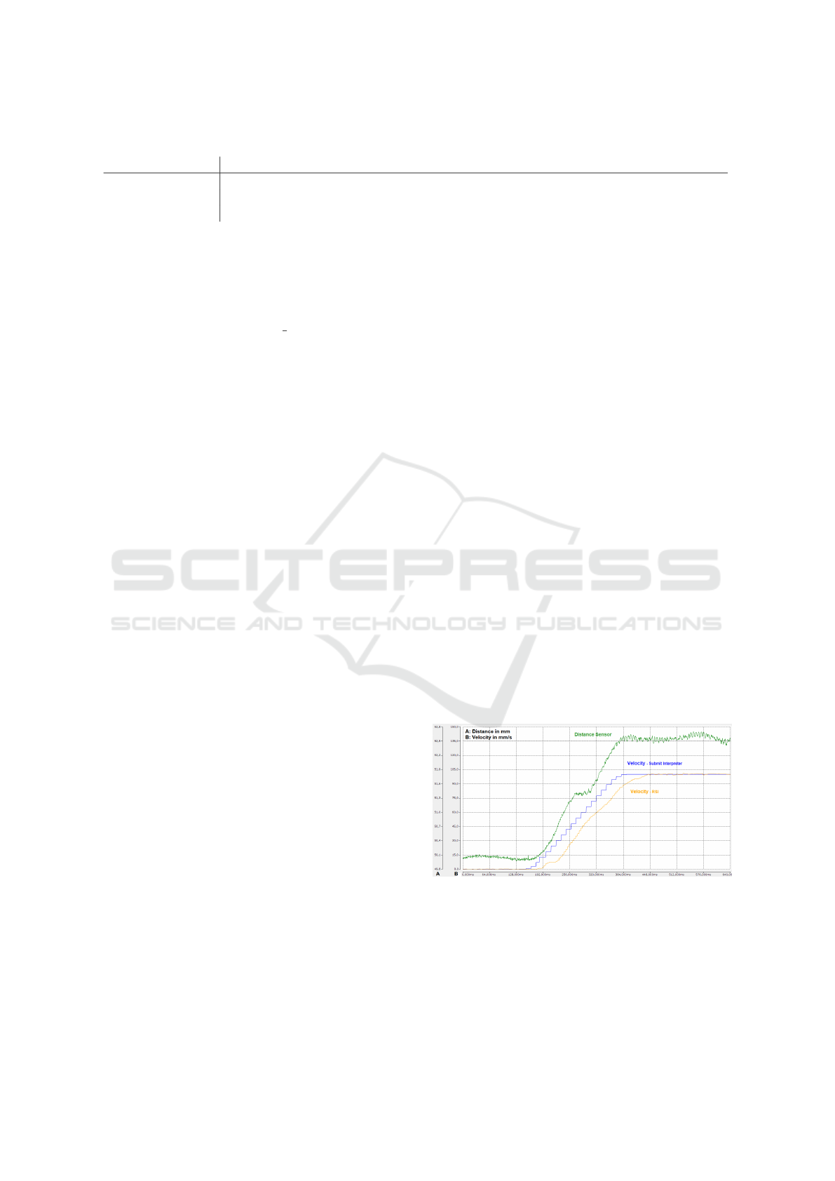
Table 1: technology overview.
Submit Interpreter RSI FSD
cycle time 12 ms 4 ms 1 ms
original purpose small cyclic tasks ext. trajectory correction triggering ext. measurments
timing behavior best effort mostly deterministic (mostly) deterministic
4.2.1 Submit Interpreter
To establish communication with the robot via the
submit interpreter, it is necessary to connect the IPC
to the robot controller using a field-bus. On the robot
side, the internal variable $ACT VEL, which contains
the speed of the TCP of the robot, is written on digital
outputs. Some care must be taken for the data format,
such as endianness or floating point number represen-
tation. The TCP speeds that have been tested were
100 mm s
−1
and 200 mm s
−1
.
4.2.2 RSI
In the case of RSI, the Beckhoff PLC is connected to
the KUKA Line Interface (KLI) on port X66 via Eth-
ernet. The communication details, such as the RSI
output format, connection properties, and XML struc-
ture for data transmission, are specified in a rsix file.
Since RSI does not provide direct access to velocity,
we choose the actual position as the output and inter-
polate the velocity. We establish unidirectional com-
munication, as only the robot needs to send data.
To implement synchronization in KRL code, the
RSI configuration must be loaded, along with the se-
lection of the corresponding coordinate system (TCP
- Tool Center Point) and signal processing mode (in
this case, a 4ms communication cycle). The PLC is
responsible for translating the robot’s trajectory into
linear axis motion. We tested speeds of 100 mm s
−1
and 200 mm s
−1
.
For reception, Beckhoff’s standard UDP module
is utilized. The received message is a XML string
with a predefined format (XML structure for data
transmission) and a timestamp known as IPOC (in-
terpolation counter).
4.2.3 FSD
To initiate the FSD protocol, a connection is estab-
lished between the PLC and the KUKA system bus
at port X47 via Ethernet UDP. For transmission and
receiving of byte-encoded UDP messages, an internal
Beckhoff UDP module is utilized.
The client needs to register with the Kuka Server
and initiate data exchange by sending a message with
the following parameters: transmission type (time-
based mode), format (position excluding orientation),
frame (TCP-frame), and time interval (1ms).
Since a message with the identifier (packet
counter) and position is sent every millisecond, it be-
comes possible to interpolate the velocity and adjust
the speed of the linear motors to follow the robot’s
trajectory. The packet counter is essential for identi-
fying sequential positions. The trajectory and speed
are defined in standard KRL code.
5 VALIDATION
This section shows the results of the measurements
and findings regarding the different communication
technologies.
5.1 Submit Interpreter
The initial measurements were conducted using the
submit interpreter. In figure 2, a section of the
recorded measurement is presented, displaying the ac-
celeration ramp. The green line represents the po-
sition data from the laser sensor, the blue line indi-
cates the velocity value transmitted via the submit in-
terpreter, and the orange line represents the velocity
calculated using the RSI position data as a reference.
One notable observation is that the data transmitted
via the submit interpreter appears to be ahead of the
data transmitted via RSI, despite RSI having a faster
transmission rate.
Figure 2: Measurement with SUB - 100 mms
−1
.
Another intriguing finding pertains to the dis-
tance measured by the laser sensor. Typically, one
would expect to observe a decrease in the distance be-
tween the robot’s aluminum plate and the laser sensor
mounted on the external axis. However, in this case,
an increase in distance is observed rather than a de-
Low-Cost Synchronization Techniques for KUKA Robots and External Axes in Low-Dynamic Processes
715

crease. This implies that the external axis is advanc-
ing ahead of the robot’s movement. The only plausi-
ble explanation for this phenomenon is that the veloc-
ity data transmitted via the submit interpreter repre-
sents the expected target speed rather than the current
speed of the robot’s TCP.
5.2 RSI
Subsequent measurements were performed using the
Robot Sensor Interface (RSI). In figure 3, a section of
the recorded measurement is presented, also display-
ing the acceleration ramp. The green line likewise
represents the position data from the laser sensor, the
orange line represents the velocity calculated using
the RSI position data, and the blue line indicates the
velocity value transmitted via the submit interpreter
as a reference. In this case, it is also noticeable that
the data transmitted via the submit interpreter appears
to be ahead of the data transmitted via RSI. However,
the distance measured by the laser sensor exhibits the
expected behavior.
Figure 3: Measurement with RSI - 100 mms
−1
.
During acceleration, the distance measured by the
laser sensor decreases (green line in figure 3), while
during deceleration, it increases. Additionally, it is
evident that the RSI transmission rate (orange) results
in a smoother signal compared to the submit inter-
preter (blue), highlighting the faster transmission rate
of RSI.
5.3 FSD
Unfortunately, we were unable to complete our mea-
surements with the FSD. During the initial test, we
observed a significant delay between the movement of
the robot and the response of the axes. This delay was
unexpected, as we had previously experienced much
lower delays in data transmission during our measure-
ments with the submit interpreter or RSI which have a
lower transmission rate. However, this time, the delay
was much more pronounced and varied depending on
the target speed. For instance, when the speed was set
at 100 mm s
−1
, we noticed a loss of 7.2 mm (as shown
by the green line in figure 4), which almost exceeds
the measurement range of ±10 mm. The delay be-
tween the robot and axis movements was so substan-
tial that we became concerned about the possibility
of a collision between the robot and the laser sensor.
Consequently, we decided to halt our series of tests.
Figure 4: Measurement with FSD - 100 mms
−1
.
Nevertheless, we were able to make some inter-
esting observations. Firstly, we noticed that the trans-
mission delay via FSD is significantly higher com-
pared to the delay via RSI. Secondly, despite the fact
that the FSD data (orange) in figure 4 appears to be
coming in at the intended rate of 1 ms, it frequently
lacks updates. In contrast, the data stream from the
submit interpreter (blue) shows a similar update rate,
with updates occurring every 12 ms. This suggests
that the update rate of the FSD Position Data is much
slower than the transmission rate of 1 ms. The combi-
nation of the considerable delay in data transmission
and the slow update rate can explain the poor perfor-
mance of FSD in this particular use case.
5.4 Submit Interpreter vs. RSI
When comparing these two methods, it is important
to note the difference in the received data. With the
Robot Sensor Interface (RSI), the current position
data of the robot is obtained, allowing for the calcu-
lation of the actual robot velocity. On the other hand,
the submit interpreter directly transmits the robot ve-
locity. However, it is essential to highlight that the
received data from the submit interpreter does not rep-
resent the actual velocity of the robot, but rather the
expected target velocity as mentioned in section 5.1.
Figure 5 shows an example of a complete mea-
surement. The Start position (1) and End position (2)
marked in red are the mean values of the sensor sig-
nal. The position data during the motion show an un-
expected drift. In order to evaluate the data, also the
mean value was determined marked with (3). This is
further discussed in (cf. section 6)
Table 2 displays the measured mean values ob-
ICINCO 2023 - 20th International Conference on Informatics in Control, Automation and Robotics
716

Figure 5: Measurement with RSI - 100 mms
−1
.
Table 2: Measurement with sensor data in [mm].
Mean value and standard deviation
Start Motion End
RSI 100 50.291 48.320 49.717
0.072 0.162 0.284
RSI 200 50.311 46.274 49.694
0.073 0.196 0.471
Sub 100 50.251 52.073 49.809
0.069 0.150 0.213
Sub 200 50.293 53.072 49.693
0.023 0.411 0.478
tained from the laser distance sensor. The second
value represents the standard deviation calculated for
each set of measurements. As can be observe, the
standard deviation is relatively low, indicating a valid
set of measurements. However, what stands out is the
increase in the standard deviation during motion. The
first value, labeled as ’start,’ refers to the distance at
the beginning of the respective test. The value labeled
as ’motion’ represents the distance during the robot
movement, and the last value, marked as ’end,’ sig-
nifies the distance at the end of the respective test.
Throughout this process, an increase in the standard
deviation can be observed. This deviation can be at-
tributed to the accuracy of our employed external lin-
ear axis and the use of a stepper motor. A similar
observation can be made in table 3. Here one can see
the mean values of the distance lost during the accel-
eration (∆ acc.) and deceleration (∆ dec.) as well
Table 3: Table of measurement with deltas in [mm].
Mean value and standard deviation
∆ acc. ∆ dec. ∆ motion
RSI 100 -1.971 1.397 0.574
0.217 0.185 0.333
RSI 200 -4.037 3.420 0.617
0.293 0.363 0.504
Sub 100 1.823 -2.264 0.441
0.197 0.168 0.244
Sub 200 2.779 -3.378 0.599
0.409 0.168 0.473
as between the start and the end of the robot move-
ment (∆ motion). At the last category, accuracies in
the range of 0.5 mm are noted, whereas an industrial
robot should typically achieve accuracies of 0.2 mm
or even 0.1 mm.
Comparing the mean values of our measurements
in table 3, two interesting observations can be made,
despite the reversal in algebraic sign (expected veloc-
ity vs. actual velocity). Firstly, the distance lost be-
tween the Robot and the laser sensor is quite similar
for both RSI and submit interpreter. This suggests that
in our use case with low speeds and dynamics, both
methods would be relatively equal in performance.
Secondly, when comparing the two different veloci-
ties, RSI 100 and 200, a doubling of the lost distance
is observed (−1.971 mm to −4.057 mm). This result
is expected, considering the doubling in robot speed.
Conversely, when comparing submit interpreter 100
and 200, less than a doubling is observed. This im-
plies that the robot, due to its higher dynamic and
torque compared to our external axis, is able to gain
ground during acceleration and deceleration.
To gain further insights into the comparison of
these methods, we propose conducting an additional
experiment. This experiment would involve a larger
and more capable external axis to determine the dy-
namics at which the submit interpreter or RSI would
experience a breakdown in accuracy. Furthermore, it
would be intriguing to examine the behavior when the
external axis possesses the ability to match the robot’s
torque and dynamics. In such a scenario, it may be
feasible to calculate acceleration delays for the robot
and external axis, thereby compensating for the for-
ward motion of the external axis. This compensation
could potentially enhance the accuracy of the submit
interpreter significantly.
6 DISCUSSION
The results obtained from the various communication
methods were quite similar, with the transmission via
submit interpreter surprisingly able to keep up with
the low speed values used. However, the experimental
setup which was presented are rather to be considered
as preliminary tests helping to create a better plan-
ning for our main experiment. Therefore, we want to
mention some major issues we want to improve be-
fore taking the next step.
Unfortunately, technical limitations associated
with the linear axis and the stepper motor prevented
testing at higher speeds. Which resulted in robot
speeds not sufficient enough to push either RSI or
the submit interpreter to their limits. Therefore, we
Low-Cost Synchronization Techniques for KUKA Robots and External Axes in Low-Dynamic Processes
717

want to use a much more capable linear axis and more
suited and powerful servo motor to achieve similar
speeds and accelerations like the industrial robot. To
take further investigations regarding some quality is-
sues with our data from the distance sensor, we will
use a servo motor with a build in motor encoder for
tracking slippage or the loss of motor steps. The rea-
son further improvements for the test setup are nec-
essary is a unexpected jump in the sensor data of the
distance sensor clearly visible in figure 2 and figure 3.
We were also able to measure a drift in the distance
data during the movement of the robot and the exter-
nal axis. While a lost in distance between the external
axis and the robot during acceleration and decelera-
tion was expected, it should not occur during a con-
stant motion. Possible reasons for this could be a loss
of motor steps or the alignment of the linear axis to
the robot coordinate system. Therefore, another quite
important improvement would be the use of two laser
trackers to get external measured position data of the
robot and external axis movement. This would give
us further insights of how good the synchronization
between robot and external axis really is.
Furthermore, it is important to improve the consis-
tency of our data transmission. While the data trans-
mission for RSI on the robot and PLC side is based
on real time the exchange happened through the win-
dows interface of the soft PLC which is not real time
capable. Therefore, we have to implement a real time
interface to ensure a clean data transmission.
Another surprising finding was the behavior of
the FSD technology package. As discussed in sec-
tion 5.3, FSD exhibited a much faster transmission
rate (1 ms) than RSI (4 ms). However, the transmitted
data was only updated every 12 ms, counteracting the
advantages of the fast transfer rate. Furthermore, FSD
demonstrated a significant delay time about 100 ms
between the start of the robot movement and the first
change of the internal position data. This topic needs
some further investigation to clarify if we are able to
find a working configuration for FSD or if it is really
not suitable for our use case.
REFERENCES
Arbo, M. H., Eriksen, I., Sanfilippo, F., and Gravdahl, J. T.
(2020). Comparison of KVP and RSI for control-
ling KUKA robots over ROS. IFAC-PapersOnLine,
53(2):9841–9846.
Bi, Z. M., Liu, Y., Baumgartner, B., Culver, E., Sorokin,
J., Peters, A., Cox, B., Hunnicutt, J., Yurek, J., and
O’Shaughnessey, S. (2015). Reusing industrial robots
to achieve sustainability in small and medium-sized
enterprises (smes). Industrial Robot: An International
Journal, 42(3):264–273.
Bilancia, P., Schmidt, J., Raffaeli, R., Peruzzini, M., and
Pellicciari, M. (2023). An overview of industrial
robots control and programming approaches. Applied
Sciences, 13(4):2582.
Kaiser, B., Wolf, M., and Verl, A. (2022). Modular control
architecture for reconfigurable fabrication systems for
prefabrication in construction. In ISR Europe 2022;
54th International Symposium on Robotics, pages 1–
7. VDE.
Kaufmann, P., Braun, G., Buchheim, A., and Malecha, M.
(2019). Automated draping of wide textiles on double
curved surfaces. In Proceedings of the 16th Interna-
tional Conference on Informatics in Control, Automa-
tion and Robotics - Volume 2: ICINCO, pages 50–58.
INSTICC, SciTePress.
Kochoski, F., Dukovski, V., Samak, S., Cvetkoska, D., and
Petkoska, B. (2022). Manufacturing thermoplastic
composites by laser automatic tape placement tool-
less technology with dual robot system. Interna-
tional Journal of Engineering Research & Technology
(IJERT), 11(4).
Kritsch, S. (2018). Konzeption, Entwicklung und Va-
lidierung von Methoden zur Synchronisation von
Roboterbewegung und externer Vorschubachse. Mas-
ter thesis, University of Applied Sciences Fulda.
Mindermann, P., Bodea, S., Menges, A., and Gresser, G. T.
(2021). Development of an impregnation end-effector
with fiber tension monitoring for robotic coreless fila-
ment winding. Processes, 9(5):806.
M
¨
ollensiep, D., Gorlas, T., Kulessa, P., and Kuhlenk
¨
otter,
B. (2021). Real-time stiffness compensation and force
control of cooperating robots in robot-based double
sided incremental sheet forming. Production Engi-
neering, 15:683–699.
Stogl, D., Zumkeller, D., Navarro, S. E., Heilig, A., and
Hein, B. (2017). Tracking, reconstruction and grasp-
ing of unknown rotationally symmetrical objects from
a conveyor belt. In 2017 22nd IEEE International
Conference on Emerging Technologies and Factory
Automation (ETFA), pages 1–8. IEEE.
Winkler, A. and Such
`
y, J. (2013). Robot force/torque con-
trol in assembly tasks. IFAC Proceedings Volumes,
46(9):796–801.
ICINCO 2023 - 20th International Conference on Informatics in Control, Automation and Robotics
718
