
Analysis of Powder Behavior Inside the Mortar During
Tableting Process
Yosuke Tachikawa
1
, Tetsu Kamiya
2
and Takanori Yamazaki
3
1
Graduate School of Science and Engineering, Graduate school of Tokyo Denki University,
Ishizaka, Hatoyama, Hiki, Saitama, 350-0394, Japan
2
Nagase&Co.Ltd., Tokiwabashi Tower, 2-6-4 Ote, Chiyoda, Tokyo, 100-8142, Japan
3
School of Science and Engineering, Tokyo Denki University, Ishizaka, Hatoyama, Hiki, Saitama, 350-0394, Japan
Keywords: Tableting, Powder Behavior, Wall Stress, Discrete Element Method.
Abstract: Tableting machines are used to make tablets from food, pharmaceutical, and other powders. It is well known
that the quality of tablets formed by tableting machines varies greatly depending on the compression
conditions, such as compression speed and compression force. Therefore, it is important to clarify the behavior
of powder inside the mortar during the compaction process. In this present research, we designed and
manufactured a thin-walled cylindrical mortar. A special strain gage was attached to the mortar to measure
the force acting on the mortar wall during tableting. Based on these results, a discrete element method (DEM)
simulation is performed, we compare and discuss the behavior of powder inside the mortar during the tableting
process.
1 INTRODUCTION
A tablet machine is a device that makes tablets from
powder by compression molding, and is widely used
in the pharmaceutical and food industries. The
advantage of using powder as tablets is the reduction
of transportation and storage costs due to the reduced
volume, which is expected to be applied not only in
the food industry but also in the materials industry
(Kamiya, 2022). Typical performance requirements
for compression molding of powders include high-
speed molding to improve productivity and high-
hardness molding to prevent tablets from
disintegrating easily (Danjo, 1998). However, the
dynamic behavior of the powder during the
compression process seems to be unclear. One of the
problems with the current product is that strength of
the top and bottom corners of the tablets are weak,
resulting in defective tablets during transportation.
In the manufacture of tablets for various kings of
pharmaceuticals, it is a major issue to optimize
tableting conditions according to the physical
properties of the various raw material powders, from
prototyping to mass production (Natsuyama, 2001).
Powder simulation is a useful solution to this issue,
and there are two major methods for this: the DSMC
and the DEM method. The DSMC method treats
particles as hard spheres. This method calculates the
time for the next collision across the system and uses
that time as a time step to translate and rotate the
particles. When particles collide, the direction of
velocity is reversed, and the velocity after repulsion
is calculated from the relative velocity before
collision and the coefficient of repulsion. The DEM
method represents a material as a collection of DEM
particles, and solve the equations of motion for the
translational and rotational motion considering the
contact force (repulsive force, frictional force),
gravity, and adhesive force (van der Waals force,
liquid bridge force) acting between particles. By
using this method, the dynamic behavior of powder
can be reproduced and predicted (Yamanoi, 2018).
The DEM method is recently gathering attention as a
simulation tool for treating with various technical
problems in the pharmaceutical, food, and lumber
processing industries using powder (Hassanpour
2010).
There are also two advantages to using the DEM
method. First, since particle collisions are considered
as soft potentials, large time steps are possible. As a
result, it can be applied to large-scale systems. The
second is applicable to high concentration systems. In
Tachikawa, Y., Kamiya, T. and Yamazaki, T.
Analysis of Powder Behavior Inside the Mortar During Tableting Process.
DOI: 10.5220/0012212000003543
In Proceedings of the 20th International Conference on Informatics in Control, Automation and Robotics (ICINCO 2023) - Volume 2, pages 297-301
ISBN: 978-989-758-670-5; ISSN: 2184-2809
Copyright © 2023 by SCITEPRESS – Science and Technology Publications, Lda. Under CC license (CC BY-NC-ND 4.0)
297
the case of compression molding, the particles are
always in contact, so the DSMC method, which treats
them as rigid spheres, is not realistic. For the above
reasons, this paper uses the DEM method.
In our previous studies, we found that the
hardness of compression-molded tablets varied
depending on the height position and confirmed that
the hardness was lower at the top and bottom of the
tablets. From these results, it was considered that the
force applied to the powder in the mortar was not
uniform. In this present research, we designed and
manufactured a thin-walled cylindrical mortar. A
special strain gage was attached to the mortar, by
using this, the force acting on the mortar wall during
tableting was measured. Furthermore, based on the
compressive forces measured in actual tableting, the
forces acting on the powder in the mortar were
calculated by simulation using the DEM method and
we discuss the behavior of powder inside the mortar
during the tableting process.
2 EXPERIMENTAL DEVICE
2.1 Tableting Machine
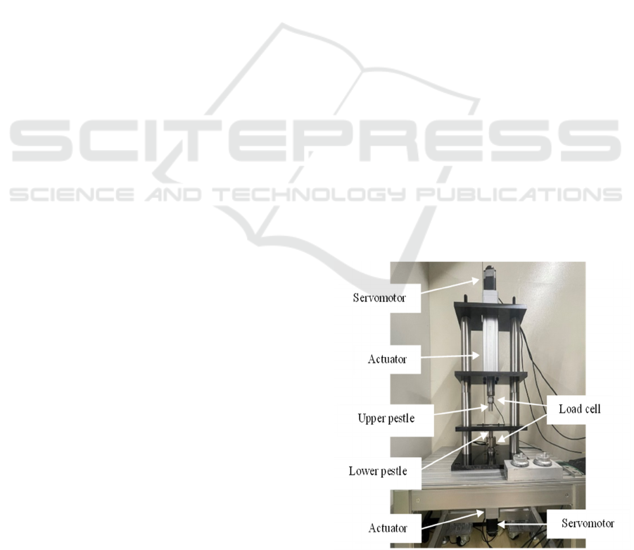
Figure 1 shows the overall structure of a tableting
machine. There are two types of tableting machines:
the single-shot type and the rotary type. In this
research, the single-shot type was adopted because
the purpose of tableting is prototyping and the
tableting conditions can be changed.
The tableting machine consists of a base plate and
three plates for installing each component on an
aluminum frame, insert a long bolt into each of the
left and right hollow shafts and fix them. the upper
and lower pestles are operated by an electric cylinder
consisting of a servo motor and a ball screw. The
pestle moves 5 mm per rotation of the motor. The
specifications of the upper and lower servo motors are
rated torque 1.15 N·m, rated current 2.8 A, and
voltage AC 200 V.
2.2 Tableting Experiment
Compression molding is performed by moving the
pestle by numerical control using a host device
(PMAC made by OMRON). In this case, the upper
pestle was used as a dynamic pestle.
The experimental procedure is, first, the sample
(powder) is weighed using an electronic balance with
an accuracy of 1.9995 g to 2.0004 g and the sample
throw inside a 20 mm-diameter mortar. Next, run the
numerical control program and form a tablet. First,
the initial position of the pestle is that the lower pestle
is 10 mm into the mortar, and the upper pestle is 50
mm from the top of the mortar. The compression
procedure is divided into two parts: the lowering and
rising motions of the upper pestle. The descending
motion performs acceleration, uniform motion, and
deceleration over a distance of 61.5 mm. The speed
of uniform motion is 1 mm/s. After the descent ends,
it begins an upward motion without stopping. The
rising motion also accelerates, moves at a constant
velocity, and decelerates over a distance of 61.5 mm.
The speed of uniform motion is 50 mm/s. This
completes one tableting motion.
After compression molding, the tablet height is
measured using a laser sensor, and the tablet mass is
measured using an electronic balance. The material of
mortar is aluminum (A5052). The shape of the mortar
is thin-walled cylindrical, a diameter of 20 mm and a
wall thickness of 1 mm. A special strain gauge was
attached the mortar to measure circumferential strain.
Figure 2 is a photo of the mortar attached to strain
gauge and their locations are shown in Figure 3. The
numbers in Figure 3 are in mm.
2.3 Experimental Results
In the tableting experiment, the compression force of
the upper pestle was 1467 N, the compression force
of the lower pestle was 803 N, and the diameter of the
upper pestle was 19.9 mm, so the upper pestle
pressure was 4.72 MPa. Although not shown in the
graph, these are the measurement results of the load
cell installed at the base of the upper and lower pestles.
These results are the average of the three experiments.
Figure 1: Tabletting machine.
ICINCO 2023 - 20th International Conference on Informatics in Control, Automation and Robotics
298

Figure 2: A mortar with a strain gauge.
Figure 3: Strain gauge position.
Figure 4 shows the measurement results of the
circumferential strain obtained in the experiment.
Using the following relational expression for a thin-
walled cylinder, The calculated internal pressure
acting on the inner wall of the mortise is shown in
Table 1. These results are the average of the three
experiments, where, 𝜎
:circumferential stress,𝑃
:
internal pressure, E : Young's modulus, 𝜀
:
circumferential strain, r:radius of the inside of the
mortar, t:wall thickness.
𝜎
𝐸𝜀
(1)
𝜎
𝑃
𝑟
𝑡
(2)
According to Table 1, the strain in the height direction
was the largest for C3 and the smallest for C1. When
the pressure acts uniformly in a pressure vessel, the
strain generated on the wall surface is considered to
be constant, but this experiment revealed that the
force acting on the inner wall of the mortar has
adistribution. We also found that even the highest C3
value is
lower
than
the
pressure
calculated
from the
Figure 4: Circumference strain.
Figure 5: Overall structure in simulation.
Table 1: Comparison of strain and internal pressure.
Determination
of position
Circumferential
strain
μS
Internal
pressure
MPa
C1 93.9 0.639
C2 166 1.12
C3 212 1.44
C4 205 1.39
C5 164 1.11
upper pestle compressive force. It was found that the
pressure applied to the wall of mortar was about
30.5% of the pressure of the upper pestle.
3 SIMULATION
3.1 Discrete Element Method
DEM is a numerical method for predicting
mechanical dynamics such as position, velocity and
motion of individual particles. The basic principles of
DEM are as follows. (a) Forces exerted by adjacent
particles or boundaries of each particle are computed
in a single time step using the contact model. (b)
Apply Newton's second law to calculate the particle
velocity. (c) Based on the same principle, the
C1
C2
C3
C4
C5
22
20
15
30
Analysis of Powder Behavior Inside the Mortar During Tableting Process
299

rotational momentum balance is solved to track the
rotational velocity of the particle. (d) New positions
of the particles are computed for the length of the time
step. This procedure is applied to each particle in a
single time step and repeated for each time step (Su,
2019).
3.2 DEM Simulation Condition
The conditions of the DEM simulation were as
follows. The tableting conditions were single stroke
tableting at 1 mm/s, the same as in the experiment.
The size of the mortar was set to 1/10 the diameter in
order to shorten the calculation time. In this analysis,
since we focused on equalizing the pressure applied
to the powder, although the actual compression
pressure was 4.72 MPa, the simulation compression
pressure was 3.85 MPa. As a result, both pressures are
almost equal at 4 MPa.
The particle size of the powder is assumed to be
200 μm. It should be noted that the average particle
size of the actual powder is about 200 μm, but which
is not so uniform. Figure 5 shows how the powder
was filled in the mortar used in the simulation.
3.3 DEM Simulation Result
Figure 6 shows the frictional forces on the upper
pestle, lower pestle, and wall calculated from the
tableting simulation. The force acting on the pestle
and wall is calculated as the sum of the forces acting
on the particles in contact with the pestle and wall.
Figure 6: Upper and lower pestle compression force, wall
friction force.
Basically, it can be found that the upper pestle
compressive force plus the wall friction force are
equal to the lower pestle compressive force.
The forces on the particle at the instant of
maximum compression are shown in Figure 7. Where,
the results are viewed from (a) top, (b) bottom, (c) 0
degree side, (d) 90 degree side, (e) 180 degree side,
and
(f) 270 degree side, respectively. First, from
(a) Top view (b) Bottom view
(c) View from 0° direction (d) View from 90° direction (e) View from 180° direction (f) View from 270° direction
Figure 7: Force on particles at maximum compression.
ICINCO 2023 - 20th International Conference on Informatics in Control, Automation and Robotics
300

Figure 7(a) and (b), it is clear that the force does not
reach the lower pestle in the case of upper pestle
compression, although there are variations. Therefore,
it is expected that the hardness of the upper part will
be higher. The results in Figures 7(c)-(f) also show
that there is variation in the state of the lateral surfaces.
Compared to the strain measured in the Figure 4, the
force at the upper end C5 is smaller, indicating that
the distribution is close to the condition shown in
Figure 7(c). In the future, it will be necessary to
improve the accuracy of the experiment, including the
position of strain measurement.
4 CONCLUSIONS
In this paper, the behavior of the powder inside the
mortar the tableting process is analyzed by
experiment and simulation.
In the experiment, we
measured the strain in the circumferential direction of
the mortar and found that the force acting on the
formed tablets varied in the height direction.
In the
simulation, there was validity between the analytical
results of the upper and lower pestle compressive
forces and the measured results. In the case of upper
pestle compression (upper pestle is driving pestle), it
was confirmed that the force acting on the upper part
of the tablet is large. It was confirmed that the force
from the upper punch was not fully transmitted to the
bottom of the tablet, and that not much force was
acting on it.
However, when looking at the side surface, the
force acting on the powder varied depending on the
angle. This was a new discovery. This suggests the
possibility that the hardness changes depending on
the direction in which the hardness test is performed.
In addition, we were able to confirm the
rearrangement of the powder, which was not seen in
the actual tableting process. It is necessary to pay
attention to the rearrangement of particles because it
greatly affects the quality of tablets (Furukawa, 2017).
In the future, we plan to conduct analysis using a
mortar that is more realistic, and to proceed with
verification by comparison with experiments.
REFERENCES
Kamiya, T., Hanyu, K. (2022). Hardening Mechanism of
Tablet Infant Formula -The Role that Synchrotron Light
Technology Carries Out-. in Japanese.
Danjo, K., Hiramatsu, A., Otsuka, A. (1998). Effect of
Pestle Velocity on the Compressibility and Stress
Relaxation of Particles and Granules. Powder
Engineering Journal. in Japanese.
Natsuyama, S. (2001). Particle Motion Analysis in Solid
Dosage Equipment by DEM Simulation and
Application to Equipment Development. in Japanese.
Yamanoi, M., Nakata, Y. (2018). Basics and application
examples of the Discrete Element Method. in Japanese.
Hassanpour, A., Tan, H., Bayly, A., Gopalrishnan, P., Ng,
B., Ghadiri, M., (2010). Analysis of particle motion in
a paddle mixer using Discrete Element Method (DEM).
Powder Technology.
Su B., Eun-Sol H., Min-Soo K., Seonf H., Sung-Joo H., Du
H. (2019). Application of the Discrete Element Method
for Manufacturing Process Simulation in the
Pharmaceutical Industry.
Furukawa, R., Kadota, K., Noguchi, T., Shimosaka, A.,
Shirakawa, Y. (2017). DEM Modelling of Granule
Rearrangement and Fracture Behaviours During a
Closed-Die Compaction. PharmSciTech.
Analysis of Powder Behavior Inside the Mortar During Tableting Process
301
