
Evaluation of Low-Cost 3D Scanner Hardware for Clothing Industry
Michael Danner
1 a
, Elena Alida Brake
1 b
, Christian Decker
1 c
, Matthias R
¨
atsch
1 d
,
Yordan Kyosev
2 e
and Katerina Rose
1 f
1
Reutlingen Research Institute, Reutlingen University, Alteburgstraße 150, Reutlingen, Germany
2
Institute of Textile Machinery and High-Performance Material Technology,
Chair of Development and Assembly of Textile Products, Technische Universit
¨
at Dresden, Dresden, Germany
{michael.danner, elena.brake, christian.decker, matthias.raetsch, katerina.rose}@reutlingen-university.de,
Keywords:
3D Body Scanner, 2D-3D Reconstruction, Textile Technology, Garment Fit, Mental Health.
Abstract:
In recent years, the demand for accurate and efficient 3D body scanning technologies has increased, driven
by the growing interest in personalised textile development and health care. This position paper presents
the implementation of a novel 3D body scanner that integrates multiple RGB cameras and image stitching
techniques to generate detailed point clouds and 3D mesh models. Our system significantly enhances the
scanning process, achieving higher resolution and fidelity while reducing the cost, time and effort required for
data acquisition and processing. Furthermore, we evaluate the potential use cases and applications of our 3D
body scanner, focusing on the textile technology and health sectors. In textile development, the 3D scanner
contributes to bespoke clothing production, allowing designers to construct made-to-measure garments, thus
minimising waste and enhancing customer satisfaction through fitting clothing. In mental health care, the 3D
body scanner can be employed as a tool for body image analysis, providing valuable insights into the psy-
chological and emotional aspects of self-perception. By exploring the synergy between the 3D body scanner
and these fields, we aim to foster interdisciplinary collaborations that drive advancements in personalisation,
sustainability, and well-being.
1 INTRODUCTION
3D body scanning technology has gained significant
attention in recent years, revolutionising various in-
dustries by providing a means for accurate, non-
invasive, and efficient body measurements. The abil-
ity to capture detailed, three-dimensional data of the
human body in mere seconds has paved the way for
countless applications, ranging from healthcare and
fitness to the textile industry and performance diag-
nostics in sports and entertainment (Schlich et al.,
2010).
Traditionally, measuring the human body has been
a time-consuming and error-prone process involv-
ing manual measurements and subjective evaluations.
The advent of 3D body scanning has not only stream-
a
https://orcid.org/0000-0002-8652-6905
b
https://orcid.org/0009-0004-7828-6501
c
https://orcid.org/0009-0003-6030-5498
d
https://orcid.org/0000-0002-8254-8293
e
https://orcid.org/0000-0003-3376-1423
f
https://orcid.org/0000-0003-4294-9700
lined this process but also enhanced the precision and
consistency of the data collected. By employing tech-
niques such as structured light, laser triangulation, or
photogrammetry, 3D body scanners can create accu-
rate digital representations of the human form, cap-
turing intricate contours and dimensions (Daanen and
Psikuta, 2018).
The versatility of 3D body scanning has allowed
for its implementation in various sectors. In health-
care, it can facilitate diagnoses, monitor progress, and
assist in rehabilitation. In fitness, it provides valuable
insights into body composition and tracking physical
changes, for example, in the analysis and diagnosis of
high-performance athletes. The textile industry bene-
fits from made-to-measure clothing pattern construc-
tion and improved sizing systems, while the entertain-
ment sector can utilise the technology for character
modelling, virtual reality, and motion capture anima-
tions capturing (Rozmus et al., 2021).
As we continue to explore the capabilities of 3D
body scanning technology, it is crucial to foster di-
alogue and collaboration among researchers, practi-
Danner, M., Brake, E., Decker, C., Rätsch, M., Kyosev, Y. and Rose, K.
Evaluation of Low-Cost 3D Scanner Hardware for Clothing Industry.
DOI: 10.5220/0012231800003543
In Proceedings of the 20th International Conference on Informatics in Control, Automation and Robotics (ICINCO 2023) - Volume 1, pages 727-735
ISBN: 978-989-758-670-5; ISSN: 2184-2809
Copyright © 2023 by SCITEPRESS – Science and Technology Publications, Lda. Under CC license (CC BY-NC-ND 4.0)
727

tioners, and industry stakeholders to address chal-
lenges, share advancements, and ultimately unlock
the full potential of this transformative technology.
This paper presents both the design and construction
of the built 3D scanner’s hard- and software as well
as the post-processing of the collected data to a 3D
avatar representation of the individual, termed as a
’scanatar’. It also includes validation of the scan-
ner’s output by comparison with existing 3D scans
and an evaluation of the scanner’s accuracy and pre-
cision against a defined list of requirements.
2 RELATED WORK
2.1 Low-Cost 3D Scanner
In the area of low-cost 3D scanning, (Iwayama, 2019)
presented a novel system that uses the Raspberry Pi
Zero W for full-body 3D scanning. Specifically de-
signed for the production of avatars in VRM format,
this system demonstrates the potential of affordable
hardware for creating detailed 3D models. Iwayama’s
approach offers valuable insights into our work, par-
ticularly in terms of cost-effective hardware usage.
Garsthagen presented a low-cost, open-source,
multi-camera, whole-body 3D scanner. It was used in
a wide range of applications and proved its versatility
and effectiveness (Garsthagen, 2014).
The research of Zeraatkar and Khalili (Zeraatkar
and Khalili, 2020) details the creation of a cost-
effective and speedy human 3D scanner, highlighting
its design, construction process, and potential appli-
cations in diverse fields, notably in areas where tradi-
tional high-cost technologies are less prevalent.
In the investigation of Kyosev and Siegmund
(Kyosev and Siegmund, 2019) the Asus RGB-D cam-
era was found to be accurate enough for the apparel
industry, with a mesh size of 3-4 mm for scanning a
human body. However, challenges were encountered
due to optical systems and body motion, resulting in
mesh discontinuities. An algorithm was developed to
evaluate gaps in the clothing based on the generated
meshes, but further research is required to overcome
limitations and achieve full automation in measuring
clothing gaps.
2.2 Scanner Operating Modes
The operational methodologies employed by low-cost
3D scanning devices can be classified into three pri-
mary techniques, namely Photogrammetry, Triangu-
lation, and Structured Light:
• Photogrammetry is a cost-effective 3D scanning
method that measures object distances using pho-
tos. It offers precise data and diverse uses. This
technique captures multiple photos from various
angles and employs software to reconstruct a 3D
model. (Journalists.org, 2020; Vedantu, 2023)
Photogrammetry is utilised in mapping, archi-
tecture, engineering, manufacturing, quality con-
trol, forensics, and law enforcement. Schenk’s
(Schenk, 2005) introduction covers photogram-
metry’s principles, applications, advancements,
challenges, limitations, and potential solutions.
• Triangulation is another technique used in 3D
scanning. It involves projecting a laser point or
line onto an object and then using a camera posi-
tioned at a known distance from the laser source to
capture the location of the laser on the object. The
distance to the object is then calculated using the
principles of triangulation(Franc¸a et al., 2005).
• Structured light projects a known pixel pattern
onto an object, allowing vision systems to cal-
culate depth and surface information. It is com-
monly used in applications like facial recognition
and body scanning. (Rocchini et al., 2001)
2.3 Areas of Application
The utilisation of 3D scanners is widespread, with
a multitude of forms and designs available, ranging
from mobile to stationary. The applications of 3D
scanners are equally diverse, with a broad range of ar-
eas in which they are employed. In various industries
and industrial manufacturing, 3D scanners are utilised
to measure, digitise, and analyse the forms and di-
mensions of construction parts, components, or other
objects.
In the realm of art and culture, 3D scans are em-
ployed to digitise art and cultural objects or recon-
struct them using the acquired data. This is done
for archiving and conservation purposes, as well as
to create virtual exhibitions or enable research with-
out the need for a physical object on site. However,
portable hand-held scanners are typically used for this
purpose, as a high level of accuracy is of utmost im-
portance (Akca et al., 2007).
In architecture and construction, the use of 3D
scanners is also common practice to create 3D mod-
els of the object and premises. This is mainly used for
precise and fast surveying for planning and visualisa-
tion in the building industry. In addition, in the field
of mapping and surveying, terrain, infrastructure and
environments can also be recorded to a certain extent
(Sepasgozar et al., 2016).
ICINCO 2023 - 20th International Conference on Informatics in Control, Automation and Robotics
728

In healthcare, 3D scanners are used for more pre-
cise detection of body parts or organs for the diag-
nosis and treatment of diseases for medical imaging
(Hitomi et al., 2015). Likewise in the medical field,
3D scanners are also used in forensics, where they can
be used to document crime scenes and capture exact
3D models of evidence (Haleem and Javaid, 2019).
In the application area of gaming and entertain-
ment, 3D scanning technology is used to create digi-
tal 3D models of real objects or people and integrate
them into virtual worlds or for motion capturing (Ya-
hav et al., 2007).
In the textile industry, 3D scanners are used in the
design and development of clothing as well as furni-
ture, accessories and seats in the automotive indus-
try. On the one hand, physical objects can be scanned
and digitised so that the dimensions and shapes can be
used in design and prototyping software, such as the
dimensions of a scanned human body. On the other
hand, objects such as car seats, furniture or even worn
clothing can be scanned so the 2D patterns can be flat-
tened from the 3D scans. (D’Apuzzo, 2007) Further-
more, body scanners can be used in this area of ap-
plication to record dynamic body dimensions, such as
the length of the back, which changes when a person
bends forward (Chi and Kennon, 2006). 3D scans are
also used to record the influence of clothing on the
body, such as changes in the shape of the human soft
tissue caused by compressive clothing or the lifting of
the breast by wearing a bra (Brake et al., 2022).
2.4 Textile Application
The use of 3D scanning technology extends to the ar-
eas of development and prototyping in clothing tech-
nology. By scanning a physical object, developers can
capture a digital model and use it in CAD systems,
which can be modified and optimised before produc-
tion. This approach not only saves time and resources
but also allows for greater creativity and experimenta-
tion in the design process. Besides scanning garments
to flatten a 2D pattern from the 3D object, 3D scan-
ners are mainly used to scan people and objects to be
measured. Capturing measurements and dimensions
via scanning allows for an error-free method and also
for fit checks in CAD to be done digitally on the avatar
or object (
ˇ
Spelic, 2020).
In addition, 3D scanners can serve as a valuable
tool for the restoration and conservation of historic
textiles and artefacts. By creating a digital replica
through scanning, experts can examine and analyse
the object without damaging the original. This tech-
nology also enables the production of replicas for ed-
ucational and exhibition purposes of historical textiles
(
˙
Zyła et al., 2021).
The use of 3D scanning technology in the textile
industry has led to significant improvements in qual-
ity control. This technology is able to detect even the
most minor flaws or inconsistencies in textile prod-
ucts, ensuring that the final product meets the highest
quality standards with a great fit. This benefits not
only the consumer but also the manufacturer, as less
waste is produced and the efficiency of the production
process is improved (Jhanji, 2018).
2.5 Contribution
Our goal is to democratise access to 3D scanning
for broad user groups who do not have financial re-
sources for a commercial system or who do not have
the know-how to design hardware and software for a
scanner device by themselves. This is achieved by
reducing the complexity, mainly through the use of
standards and adherence to best practices that work in
the environments of those user groups.
The full-body 3D scanner was built using com-
mercial off-the-shelf (COTS) cameras and computing
hardware. The software then allows different parts to
act like a single device. This paper presents the de-
sign and construction process and the performance of
the built 3D scanner but with only 48 cameras. It also
includes validation and evaluation of the scanner’s ac-
curacy and precision against a defined list of require-
ments. The main problem addressed in this study is
the need for a cost-effective yet accurate 3D scanner
that can be used in the field of apparel engineering by
researchers who are not software experts.
Figure 1 shows our installation of the 3D scan-
ner. It consists of 48 Raspberry Pi 4 model B (RPi,
2023a) computers mounted in a frame around a 2m x
2m ground plate. Each Raspberry Pi connects to an
8 Megapixel camera module v2.1 (RPi, 2023b). The
subject stands in the middle of the ground plate, and
all surrounding cameras capture pictures simultane-
ously. These pictures are downloaded by a user for
post-processing, stitching all single pictures together
to create a 3D image.
The scanning software project is open source and
available on Github
1
.
2.6 Definition of Requirements
From the previous definitions of the areas of applica-
tion and possible options for using the scanner, it is
important to precisely define the requirements to be
met by the scanner in order to use it in these specific
cases.
1
https://github.com/cdeck3r/3DScanner
Evaluation of Low-Cost 3D Scanner Hardware for Clothing Industry
729

Figure 1: 3D Scanner installation.
• Capturing body measurements: The scanner must
be able to capture precise measurements of body
dimensions such as lengths, girths and circumfer-
ences (Bartol et al., 2021). This is important to
construct and produce customised garments.
• Capture of body forms: The scanner should also
be able to capture the whole individual body
shapes and proportions of each scanned indi-
vidual, including special physical characteristics
such as asymmetries. This is important to ensure
a correct fit, taking into account individual physi-
cal conditions (Ashdown et al., 2004).
• Speed: The scanner should capture data as
quickly as possible in under 1 second and be effi-
cient to save time and optimise workflow.
• Accuracy: The scanner should be highly accu-
rate to ensure that the captured data is reliable
and allows for precise measurement of the body.
The maximum deviation of the scan from the real
dimensions of the body should be within 5mm
(
ˇ
Spelic, 2020).
• Compatibility: The scanner should be compatible
with various software and hardware systems to en-
sure smooth integration into existing workflows.
The above requirements were identified through an
analysis of the specific needs and challenges of the
apparel industry (Kyosev and Siegmund, 2019; Istook
and Hwang, 2001; Nayak et al., 2015). They serve
as the basis for the design and construction of a 3D
scanner for this application area. The following sec-
tion describes in detail the process of planning and
constructing the scanner in terms of hardware and the
developed software.
3 3D SCANNER SYSTEM DESIGN
While a similar hardware setup was found in a previ-
ous work (Iwayama, 2019), we aimed at a design to
significantly lower the entry bar to set up and oper-
ate such a scanner. This is achieved by reducing the
complexity, mainly through the use of standards and
adherence to best practices that work in the environ-
ments of our user groups. We present and discuss the
design of the 3D full-body scanner from three per-
spectives:
• Network, i.e., we describe the setup of the scan-
ner’s hardware components
• Structure, i.e., we report about the scanner’s soft-
ware components and protocols
• Behaviour, i.e., we illustrate how the cameras
work together to take synchronised pictures from
all angles around the subject
Finally, we briefly portray some relevant operational
aspects to complement the design description.
3.1 Network Setup
Our main objective was to develop an easy setup that
adheres to the best practices that work in the envi-
ronments of our user groups. Figure 2 illustrates the
network setup. All Raspberry Pi computers connect
scanner network
uplink network
Internet
Camera
«Raspberry Pi»
camnode
«Raspberry Pi»
centralnode
switch
router
firewall DHCP server Smartphone
GitHub.com Developer PC
User
Developer
1
1
1
0..*
1 0..*
VPN connection
Figure 2: Scanner network setup.
to a switch and form a scanner network, which is con-
nected to an uplink network via a router. The latter
provides network services such as IP address assign-
ment (via the DHCP server) to all Raspberry Pi com-
puters. The user connects the smartphone with the
uplink network, typically via WiFi, to access and con-
trol the scanner. A firewall shields the uplink network
from the Internet and restricts access. The Internet
hosts a code repository for software provision admin-
istered by a developer.
ICINCO 2023 - 20th International Conference on Informatics in Control, Automation and Robotics
730

The uplink network is an infrastructure network
with an Internet connection through a router. It is
already available in the user’s environment. Typical
uplink networks are in-house university networks or
even everybody’s home networks. In the latter, stan-
dard home routers given to the user by their ISP pro-
vide all the functionality of the uplink network from
our design. As a result, the only setup activity left
to the user is to connect all Raspberry Pi computers
to the switch and then plug it into the router of the
uplink network.
From a network perspective, the scanner does not
form a separate subnet but only consists of several
networked camera devices operating in the same IP
subnet as the uplink network. Therefore, from this
perspective, camera devices do not differ from the
user’s smartphone. In the same way, a user connects
a smartphone to the uplink network, and the user con-
nects the scanner’s camera devices. Consequently, ad-
ditional network management activities such as IP as-
signment and routing are not required.
This is different from previous works, such
as (Iwayama, 2019), where the camera devices are
organised in a separate IP subnet to form a logical
structure, which is then controlled by software. This
adds to the complexity we want to avoid. In the fol-
lowing section, we describe our approach to creating
a logical structure for networked devices.
3.2 Logical Structure
We must know all the networked cameras of the scan-
ner to control them in an organised manner. Thus,
we define a logical structure. First, we abstract the
concrete hardware by naming the Raspberry Pi com-
puters according to their functional roles. Thereby,
we distinguish between two roles: camnode and cen-
tralnode. The camnode is a Raspberry Pi connected
to a camera. The centralnode is a Raspberry Pi that
controls all camnodes and provides a web-based GUI
to the user via a web server. Figure 3 shows the
UML diagram of the structure. Both nodes con-
nect and exchange messages via the MQTT publish-
subscribe protocol (OASIS, 2019), a well-known de-
facto standard from the Internet of Things (IoT) do-
main. Central to this concept is a broker that col-
lects all messages and forwards them from publish-
ers to subscribers. The MQTT broker is part of the
centralnode. Each camnode connects to the broker
via an MQTT client. The number of camnodes is not
fixed. Zero to many camnodes could be connected to
the broker.
The MQTT broker utilises hierarchically organ-
ised message topics. The figure 4 shows an ex-
«Raspberry Pi»
centralnode
«Raspberry Pi»
camnode
webserver
MQTT broker MQTT client
GUI
camera
1
0..*
Figure 3: UML diagram of the abstract model for the scan-
ner’s system structure.
ample of a tree-like topic hierarchy. In this ex-
scanner/
scanner/button
scanner/camnode1/button
scanner/camnode1/image
scanner/camnode2/button
scanner/camnode2/image
...
Figure 4: Example of a MQTT topic hierarchy.
ample, the scanner topic serves as the root and
subsumes the camnodes as subtopics, for example,
scanner/camnode1. Below each camnode topic are
other topics, such as pushing the camera button or
providing the captured image. The scanner/button
topic represents the function of pushing all the camera
buttons simultaneously.
Topics can have two purposes: to publish a mes-
sage to a topic and to subscribe to a topic. The first
purpose corresponds to sending a message, and the
second is to receive a message. All message exchange
interactions run through the broker, maintaining the
current state of all the nodes. This tree-like struc-
ture serves in two ways: first, as an organisational
structure for collecting and naming all known scanner
hardware components, and second, as an interface to
communicate with the named components.
This approach enables loose coupling. It works
like a marketplace - whoever is on the place, that is,
connected to the broker, is part of the scanner and
provides services, for example, pushing a button or
providing an image. If a camnode fails, the scanner
still works as expected but takes one image less. This
makes the scanner resilient to camnode failure. If a
user installs more camnodes, the scanner seamlessly
integrates their services. No separate software up-
dates are required. This renders the scanner a web
of many interacting cameras, and the structural sys-
tem model enables them to behave like a single large
device.
Evaluation of Low-Cost 3D Scanner Hardware for Clothing Industry
731

3.3 Software Behavior
Using the above structure, the scanner’s behaviour is
determined by a sequence of message exchanges via
MQTT. The UML sequence diagram in Figure 5 il-
lustrates this, which shows the interaction between
a centralnode and all camnodes when capturing im-
ages. Initially, all camnodes subscribe to the topic
User
User
GUI
GUI
«centralnode»
MQTT broker
«centralnode»
MQTT broker
«camnode»
MQTT client
«camnode»
MQTT client
camera
camera
subscribe
scanner/button
hit bu tto n
publish
but t on to
scanner/button
but t on
take picture
png file
publish png to
scanner/camnode/image
store png
on filesystem
png file on
centralnode
download
png file
get png file
from filesystem
png file
Figure 5: UML sequence diagram for taking pictures.
scanner/button on the central node’s MQTT bro-
ker. In the web browser, the user hits the button on the
web-based UI to take images from all camnodes. This
command is published to the topic scanner/button.
Because all camnodes are subscribed to this topic,
they receive the button command synchronously.
Each camnode then takes an image and publishes it to
the broker under the topic scanner/camnode/image,
where the camnode subtopic is enumerated to distin-
guish the images from each other. The broker re-
ceives all images and stores them as files in its file
system. Finally, the user accesses all images via a
web browser for download.
3.4 Operation
We briefly portray some relevant operational aspects
to complement the design description.
3.4.1 Jitter
An important characteristic of a functional 3D scan-
ner is the jitter in the image creation time. The larger
the jitter, the longer the subject must stand still to
avoid blurring of the reconstructed 3D image. All
Raspberry Pi computers have synchronised system
clocks. This allows us to compare the image creation
times of all camnodes. We measured the jitter, that is,
the range across all creation times, in several runs and
found it always below 100ms.
3.4.2 Remote Maintenance and Update
Although the loosely coupled approach of the scan-
ner design makes it resilient and extendable, assis-
tance for maintenance or failure analysis by an ex-
ternal software expert may be required. In Figure 2,
a software developer can access the scanner’s Rasp-
berry Pi computers remotely from the Internet via
VPN and support these activities.
An important part of these activities is updating
the software on the Raspberry Pi computers. The code
was versioned in the Github repository, as shown in
Figure 2. When a code update is requested, the Rasp-
berry Pi reboots and updates its software from the
repository when booting. This allows all Raspberry
Pi computers to be updated simultaneously. Finally,
after the update, the camnode device must reconnect
to the central node MQTT broker to re-establish the
logical structure.
The code repository serves as a single source of
truth. This allows the system to automatically check
that all Raspberry Pi computers work with the same
and the most recent software version. This prohibits
intermittent behaviour in such a distributed system
design caused by deviating software versions.
3.4.3 Single Point of Failure
Both centralnode and camnode are Raspberry Pi com-
puters. The nodes’ roles are not mutually exclusive,
i.e., a Raspberry Pi may work in both roles, centraln-
ode and camnode, at the same time. However, if there
is only one Raspberry Pi with a centralnode role, it
represents a single point of failure. When this device
fails, the MQTT broker disappears and the scanner’s
logical structure dissolves. However, an MQTT bro-
ker can work in the failover mode, that is, if one bro-
ker fails, another redundant one on another Raspberry
Pi takes over. This mitigates the problem of a single
point of failure and does not require additional hard-
ware or software.
3.4.4 Security Considerations
The Raspberry Pi computers are part of the uplink net-
work and are therefore accessible to all devices in this
network, as well as from the Internet. Therefore, we
applied the following measures to secure them with-
out limiting the functionality of the scanner to the
user.
It is recommended and already often seen imple-
mented practice to shield the uplink network from the
ICINCO 2023 - 20th International Conference on Informatics in Control, Automation and Robotics
732
Internet using a firewall and restrict remote access us-
ing VPN. Even in home networks, firewalls are in-
stalled on the router provided by the user’s ISP. More-
over, all password-based logins to the Raspberry Pi
computers are disabled, and only cryptographic key-
based logins are allowed. This secures the scanner
from unintended and malicious access from the up-
link network and the Internet. However, physical ac-
cess to these devices may undermine these security
measures.
4 3D IMAGE RECONSTRUCTION
Once the images were captured and downloaded from
3D scanner’s centralnode, post-processing starts to re-
construct the 3D image.
4.1 Image Preprocessing
The preprocessing involves adjusting the images’
brightness, contrast, and colour temperature. This is
crucial to ensure that the images are neither too bright
nor too dark, have sufficient contrast to distinguish
between different objects and have a correct colour
temperature that accurately represents the colours in
the scene.
The second step involves adjusting the exposure of
the images. This is important to ensure that all parts
of the image are correctly exposed and that no areas
are overexposed or underexposed.
The final step in the preprocessing pipeline is
white balancing. This is necessary to ensure that
the colours in the images are represented accurately.
White balancing corrects the colours by removing any
colour casts caused by the lighting conditions under
which the images were taken.
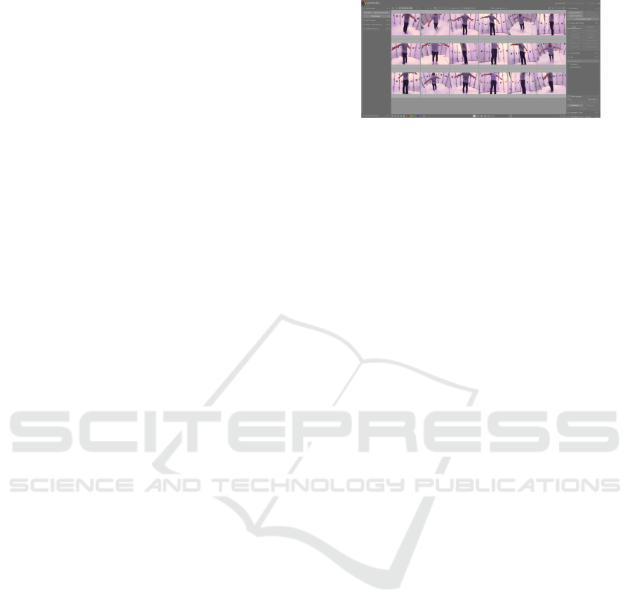
For our experiments and to test our hardware and
software architecture, we used in this attempt the free
software Darktable, see figure 6 to apply these adjust-
ments to multiple images. The preprocessing of im-
ages is a critical step in the photogrammetry work-
flow. By adjusting the brightness, contrast, colour
temperature, and exposure and performing white bal-
ancing, we can significantly improve the quality of the
input images and, consequently, the accuracy of the
photogrammetric analysis. Darktable provides a com-
prehensive and user-friendly interface for performing
these preprocessing steps.
4.2 Photogrammetry
This section outlines the post-processing steps and
practical application of RealityCapture (Capturing
Figure 6: Preprocessing in Darktable.
Reality, 2023) in photogrammetry. The process in-
volves the collection of 48 images, alignment of these
images using AprilTag markers, model calculation,
texture application and mesh colourisation. For this
procedure, MATHLAB can also be considered, there
are different solutions for stitching the images (Math-
Works, ided). For this specific project, a total of
48 images were collected. The quality of these im-
ages significantly impacts the accuracy of the final 3D
model, so it is essential to ensure that the images are
high-resolution and cover the object of interest from
multiple angles.
The next step is to align the images. This is done
using AprilTag markers, a type of fiducial marker sys-
tem. These markers are placed in the scene before im-
age collection, providing a common reference point
across multiple images. For this work, 16 AprilTag
markers were used to align the 48 images accurately.
After the images have been aligned, the next step
is calculating the 3D model. This involves calibrating
the cameras and markers in 3D space. The calculation
uses the aligned images and the known positions of
the AprilTag markers to calculate the 3D positions of
the cameras and to generate a 3D model of the scene.
The final step in the process is applying texture
to the 3D model and colourising the mesh. We use
the colour information from the original images to
generate a realistic texture for the 3D model and to
colourise the mesh. This results in a final 3D model
that accurately represents the colours and textures of
the original scene.
5 EVALUATION
For the investigation of the generated 3D scans and
their suitability for textile development, the scans of
3 different test persons were first visually examined
since artefacts and rough inaccuracies were already
visible at first glance.
As seen in Figure 7, especially in the area of the
legs, the inaccuracies are the largest, so the calves are
barely captured, and there are also erroneous connec-
tions between the legs.
Evaluation of Low-Cost 3D Scanner Hardware for Clothing Industry
733
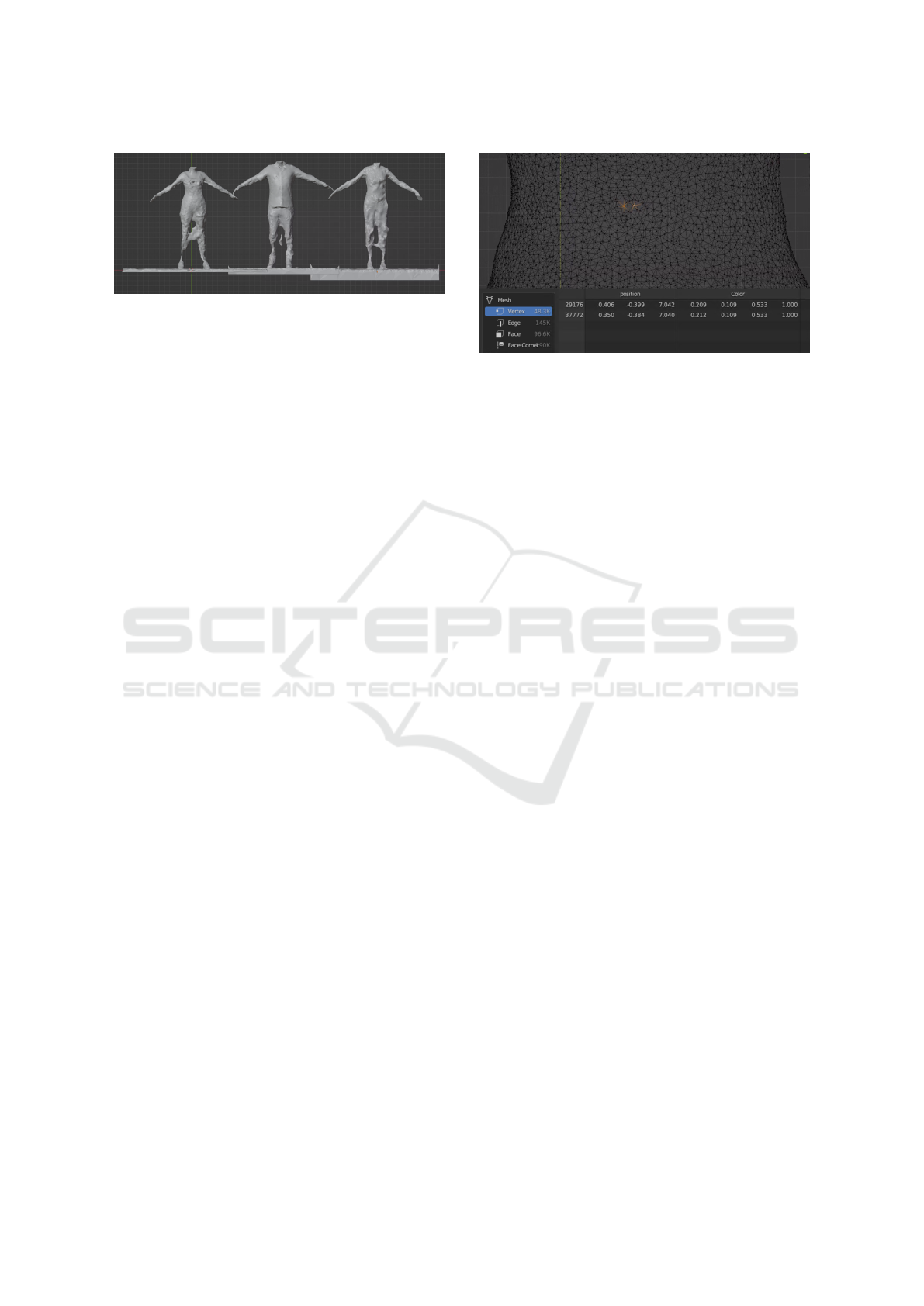
Figure 7: 3D Scans Evaluation.
The inaccuracies on the torso, on the other hand,
are moderate. Still, when the scan is observed visually
alone, it can already be seen that the accuracy and the
mesh do not meet the previously defined requirements
for 3D scans to be used for textile applications. There-
fore, the generated 3D scans are not yet sufficient for
measuring the body dimensions for comparison with
the actual dimensions of the test persons.
6 RESULTS
In this section, we delve into an analytical dis-
course concerning the outcomes derived from the
photogrammetric processes of our 3D scanner. Given
that these constitute our inaugural 3D scans, the re-
sults are beneficial and exhibit a promising trajectory
for future endeavours. For data security and privacy
protection, we truncated the head from the data set.
However, it is noteworthy to mention that, as
pointed out in the evaluation, minor complications
were encountered in the representation of the legs.
Potential resolutions for these issues could include
incorporating additional AprilTag markers, which
would provide more reference points for the align-
ment of images. Alternatively, an enhancement in the
camera resolution could also contribute to rectifying
these issues by capturing more detailed and higher-
quality images.
Looking at the mesh of the scans, we see a very
high amount of data. As shown in Figure 8, the mesh
of test person 1 consists of 48.3K vertices, and the
distance between them is about 0.5 cm.
7 CONCLUSION
In conclusion, this paper presents the design, opera-
tion, and validation of a low-cost 3D scanner system
that utilises Raspberry Pi computers and MQTT pro-
tocol for image capture and processing. The scan-
ner’s software behaviour is determined by a sequence
of message exchanges via MQTT, and the system is
Figure 8: 3D Scan Mesh Vertex distance.
designed to be resilient and extendable, with provi-
sions for remote maintenance and updates. The sys-
tem’s operation is characterised by low jitter in image
creation time, and the potential for a single point of
failure is mitigated by the failover mode of the MQTT
broker. The paper also discusses the post-processing
steps involved in 3D image reconstruction, including
image preprocessing and photogrammetry.
The paper provides a consideration of the scan-
ner’s accuracy and precision and discusses the results
derived from the photogrammetric processes. While
the results are promising, minor complications were
encountered in the representation of the legs, which
could potentially be resolved by incorporating addi-
tional AprilTag markers or enhancing the camera res-
olution.
The previously defined requirements for the scan-
ner used in the textile industry, such as speed and
compatibility, were already met in the first attempt.
The criteria that the scanner should capture body di-
mensions and shapes were also met, but not accu-
rately enough for the intended use. The artefacts and
inaccuracies already detected visually are too signifi-
cant for the scans to be used for the generation of mea-
surement tables or for the processing of patterns, but
by optimising the image quality to improve the scan
quality, the next step is to recheck the accuracy of the
scans for measurement and dimension accuracy.
In future work, the system will be further opti-
mised and expanded to improve its performance and
versatility. The scanner represents a valuable tool for
3D image capture and reconstruction, with potential
applications in a wide range of fields.
REFERENCES
Akca, D., Gruen, A., Breuckmann, B., and Lahanier, C.
(2007). High definition 3d-scanning of arts objects
and paintings. Optical 3-D measurement technqiues
VIII, 2:50–58.
ICINCO 2023 - 20th International Conference on Informatics in Control, Automation and Robotics
734

Ashdown, S. P., Loker, S., Schoenfelder, K., and Lyman-
Clarke, L. (2004). Using 3d scans for fit analysis.
Journal of Textile and Apparel, Technology and Man-
agement, 4(1):1–12.
Bartol, K., Bojani
´
c, D., Petkovi
´
c, T., and Pribani
´
c, T.
(2021). A review of body measurement using 3d scan-
ning. Ieee Access, 9:67281–67301.
Brake, E., Kyosev, Y., and Rose, K. (2022). 3d garment fit
on solid and soft digital avatars–preliminary results.
Communications in development and assembling of
textile products, 3(2):97–103.
Capturing Reality (2023). Realitycapture. https://www.
capturingreality.com/. Accessed: 2023-07-01.
Chi, L. and Kennon, R. (2006). Body scanning of dynamic
posture. International Journal of Clothing Science
and Technology, 18(3):166–178.
Daanen, H. A. and Psikuta, A. (2018). 3d body scanning.
In Automation in garment manufacturing, pages 237–
252. Elsevier.
D’Apuzzo, N. (2007). 3d body scanning technology for
fashion and apparel industry. In Videometrics IX, vol-
ume 6491, pages 203–214. SPIE.
Franc¸a, J. G. D., Gazziro, M. A., Ide, A. N., and Saito, J. H.
(2005). A 3d scanning system based on laser trian-
gulation and variable field of view. In IEEE Inter-
national Conference on Image Processing 2005, vol-
ume 1, pages I–425. IEEE.
Garsthagen, R. (2014). An open source, low-cost, multi
camera full-body 3d scanner. In Proc. of 5th Int. Conf.
on 3D Body Scanning Technologies, pages 174–183.
Haleem, A. and Javaid, M. (2019). 3d scanning applications
in medical field: a literature-based review. Clinical
Epidemiology and Global Health, 7(2):199–210.
Hitomi, E. E., Silva, J. V., and Ruppert, G. C. (2015). 3d
scanning using rgbd imaging devices: A survey. De-
velopments in Medical Image Processing and Compu-
tational Vision, pages 379–395.
Istook, C. L. and Hwang, S.-J. (2001). 3d body scanning
systems with application to the apparel industry. Jour-
nal of Fashion Marketing and Management: An Inter-
national Journal, 5(2):120–132.
Iwayama, Y. (2019). Real avatar production-raspberry pi
zero w based low-cost full body 3d scan system kit for
vrm format. In Proceedings of the 10th International
Conference and Exhibition on 3D Body Scanning and
Processing Technologies, Lugano, Switzerland, pages
22–23.
Jhanji, Y. (2018). Computer-aided design—garment de-
signing and patternmaking. In Automation in garment
manufacturing, pages 253–290. Elsevier.
Journalists.org (2020). A guide to photogrammetry photog-
raphy. Accessed: 2023-06-12.
Kyosev, Y. and Siegmund, J. (2019). Evaluation of the accu-
racy and suitability of low-cost rgb-d sensors for auto-
mated air gap measuring in the apparel industry. Pro-
ceedings of 3DBODY.TECH 2019.
MathWorks (Year not provided). triangulatemultiview func-
tion - matlab documentation.
Nayak, R., Padhye, R., Wang, L., Chatterjee, K., and Gupta,
S. (2015). The role of mass customisation in the ap-
parel industry. International Journal of Fashion De-
sign, Technology and Education, 8(2):162–172.
OASIS (2019). MQTT Version 5.0. https://mqtt.org/
mqtt-specification/. Accessed: June 27, 2023.
Rocchini, C., Cignoni, P., Montani, C., Pingi, P., and
Scopigno, R. (2001). A low cost 3d scanner based
on structured light. In computer graphics forum, vol-
ume 20, pages 299–308. Wiley Online Library.
Rozmus, M., Tokarczyk, J., Michalak, D., Dudek, M.,
Szewerda, K., Rotkegel, M., Lamot, A., and Ro
ˇ
ser,
J. (2021). Application of 3d scanning, computer sim-
ulations and virtual reality in the redesigning process
of selected areas of underground transportation routes
in coal mining industry. Energies, 14(9):2589.
RPi (2023a). Raspberry Pi 4 Model B by the Raspberry Pi
Foundation. https://www.raspberrypi.com/products/
raspberry-pi-4-model-b/. Accessed: June 27, 2023.
RPi (2023b). Raspberry Pi NoIR Camera V2 by the Rasp-
berry Pi Foundation. https://www.raspberrypi.com/
products/pi-noir-camera-v2/. Accessed: June 27,
2023.
Schenk, T. (2005). Introduction to photogrammetry. The
Ohio State University, Columbus, 106:2005.
Schlich, E., Schumm, M., and Schlich, M. (2010). 3d-body-
scan als anthropometrisches verfahren zur bestim-
mung der spezifischen k
¨
orperoberfl
¨
ache. Ern
¨
ahrungs
Umschau, 57(4):178–183.
Sepasgozar, S. M., Shirowzhan, S., et al. (2016). Challenges
and opportunities for implementation of laser scanners
in building construction. In ISARC. Proceedings of the
international symposium on automation and robotics
in construction, volume 33, page 1. IAARC Publica-
tions.
ˇ
Spelic, I. (2020). The current status on 3d scanning and
cad/cam applications in textile research. Interna-
tional Journal of Clothing Science and Technology,
32(6):891–907.
Vedantu (2023). Photogrammetry. Accessed: 2023-06-12.
Yahav, G., Iddan, G. J., and Mandelboum, D. (2007). 3d
imaging camera for gaming application. In 2007 Di-
gest of Technical Papers International Conference on
Consumer Electronics, pages 1–2. IEEE.
Zeraatkar, M. and Khalili, K. (2020). A fast and low-cost
human body 3d scanner using 100 cameras. Journal
of Imaging, 6(4):21.
˙
Zyła, K., Kesik, J., Santos, F., and House, G. (2021). Scan-
ning of historical clothes using 3d scanners: Compar-
ison of goals, tools, and methods. Applied Sciences,
11(12):5588.
Evaluation of Low-Cost 3D Scanner Hardware for Clothing Industry
735
