
A Methodology for Knowledge Integration and Acquisition in
Model-Based Systems Engineering
Luis Palacios Medinacelli
a
, Florian Noyrit
b
and Chokri Mraidha
c
Universit
´
e Paris-Saclay, CEA, List. Palaiseau, France
{luis.palacios, florian.noyrit, chokri.mraidha}@cea.fr
Keywords:
Domain-Specific Ontologies, Knowledge Integration, MBSE, Semantic Interoperability.
Abstract:
In Model-Based System Engineering (MBSE) systems are represented as models using a predefined meta-
language such as SysML that hides some of the complexity behind the specification of a system, and provides
experts with a rich syntax to define, share and constrain these models. Even though current MBSE design tools
are sophisticated and support expressive meta-languages, these tools have limited capabilities on the detection
of semantic errors, the integration of expert knowledge, or the ability to formalize the knowledge from the
expert’s design. Our work addresses these limitations by annotating the SysML models with domain-specific
ontologies. Enabling this interaction not only makes the ontology’s semantics available to the tooling envi-
ronment, but the UML model specified by the designer can be translated into Ontology Web Language format
(OWL), generating a system specification in terms of the ontology. These ”annotated models” are suitable for
reasoning tasks, like consistency check and instance checking. We particularly ensure the annotated model
is a consistent extension of the domain-specific ontology, thus formalizing the expert’s knowledge as a sub-
ontology. This extended ontology can be re-used and shared to evaluate and constrain further models, or be
itself evaluated by semantic-compatible tools. In this article we present our approach for an OWL-MBSE
integration, and show its feasibility via an implementation in the UAVs domain.
1 INTRODUCTION
Complex systems design, like Autonomous or Cyber-
Physical Systems, require specific design and engi-
neering techniques to ensure the resulting systems
comply with their specifications. Among these tech-
niques Model-Based System Engineering (MBSE)
provides good practices and formalized syntax that
make the engineering process systematic.
It notably helps in sharing the same interpretation
of the models among experts. Among the existing
modeling languages available for complex system de-
sign we consider SysML
1
, a UML
2
profile for system
engineering. These languages have a very rich ex-
pressiveness. The sophistication of current modeling
tools is correlated to this high expressiveness, thus re-
quiring high expertise in the tool’s specific represen-
tation language. Moreover, new modeling projects
have to be built from scratch, rebuilding structures
a
https://orcid.org/0000-0002-9413-4119
b
https://orcid.org/0000-0001-5947-7258
c
https://orcid.org/0000-0003-2993-5734
1
https://www.sysml.org/
2
https://www.uml.org/
and descriptions that are common to specific domains
(e.g. Autonomous Systems), where knowledge reuse
is available in a limited way (e.g. model libraries).
Despite the formal syntax of MBSE, its semantics are
expressed in natural language, which poses a limi-
tation for interpretation, sharing and reuse of these
models. Moreover, because different stakeholders and
different projects may define the same systems dif-
ferently, semantic interoperability and the construc-
tion of knowledge bases from these system models
remains challenging. The use of formal semantics is
essential for explicit, shareable, and reusable knowl-
edge representation (Yang et al., 2019).
There exists extensive research (Yang et al., 2019;
Atkinson and Kiko, 2005; Berardi et al., 2005; Par-
reiras, 2011) on the benefits and potential of the in-
teraction and integration of MBSE and ontologies.
These vary from providing reference concepts and
the definition of homogeneous terminologies, to al-
lowing for machine-readable axioms and integration,
exchange and reuse of knowledge, among others. It
is also noted in these works the challenges for a
successful integration, among which we find: the
(un)availability of the required ontologies along with
264
Medinacelli, L., Noyrit, F. and Mraidha, C.
A Methodology for Knowledge Integration and Acquisition in Model-Based Systems Engineering.
DOI: 10.5220/0012233900003598
In Proceedings of the 15th International Joint Conference on Knowledge Discovery, Knowledge Engineering and Knowledge Management (IC3K 2023) - Volume 2: KEOD, pages 264-271
ISBN: 978-989-758-671-2; ISSN: 2184-3228
Copyright © 2023 by SCITEPRESS – Science and Technology Publications, Lda. Under CC license (CC BY-NC-ND 4.0)

their documentation; the different levels of abstrac-
tion and viewpoints, where the domain and scope of
the ontology needs considerable effort to be aligned
to a new application domain; the different interpreta-
tions of a given language construct depending on the
viewpoint; and the gap between theoretically focused
approaches and real-world applications.
To enable the interaction between different view-
points and representations, and to enable the appli-
cation and reuse of ontological knowledge within
MBSE, in this article we present a formal approach
to integrate and extract knowledge, expressed as an
ontology, into/from MBSE tools.
Our approach emphasizes in the following chal-
lenges : 1) The integration of standardized and
domain-specific languages, 2) The definition of the
components a bidirectional mapping (OWL-UML)
should consider, guided by the expressivity of specific
description logic languages, 3) The ability to capture
complex system structures and describe them as com-
plex ontological definitions 4) the reuse of the cap-
tured knowledge.
In this paper we present the formalization of our
approach, to integrate standardized domain-specific
ontologies into MBSE tooling environments, and
show its feasibility via an implementation in the
UAVs (Unmanned Aerial Vehicles) domain.
The rest of this paper is organized as follows: in
section 2 we present the works related to ontologies
and MBSE. In section 3 we present our approach.
In section 4 we present an implementation of the ap-
proach, motivated by the UAVs use case. Finally, we
present our conclusions in section 5.
2 RELATED WORKS
In this section, we present some of the most relevant
works regarding ontologies, UML/SysML and MBSE
technologies. These works present the motivations,
state of the art, challenges, and envisaged benefits
from the interaction of the aforementioned technolo-
gies. A recurrent issue addressed by works combining
UML and ontologies is the problem of semantic het-
erogeneity in distributed and delocalized companies,
where problems of misunderstanding and information
exchange may arise, due to different viewpoints, for
which applications are developed (Parreiras, 2011;
Elasri and Sekkaki, 2013). There is also the risk of
loss of information when exchanging between hetero-
geneous systems. In these works, the use of ontolo-
gies as models is proposed to trace relevant and shared
information related to the knowledge domain in ques-
tion.
The work in (Atkinson and Kiko, 2005) evidences
that there is a lack of a complete mapping between the
constructs of the two languages. Although, within the
terminology of an ontology, there might be specific
concepts and relations that suit specific UML con-
structs, allowing for a more complete mapping.
The work in (Berardi et al., 2005) explores the
expressivity and reasoning complexity in UML di-
agrams, and the work in (Parreiras, 2011) aims to
provide an integrated approach for UML class-based
modeling and ontology modeling. There are sev-
eral areas of system engineering (SE) knowledge
where research between ontologies and SE has been
conducted (Yang et al., 2019): System Fundamen-
tals, System engineering Standards, Generic Life Cy-
cle Stages, Representing Systems with Models, En-
gineered System Contexts and System Engineering
Management. The works considered in (Yang et al.,
2019) summarize the causes for the difficulties in de-
veloping systems on budget and on time, and the con-
siderable resource waste dealing with the correction
of mistakes, into four reasons: 1) the implicit nature
of SE, 2) the limitations of best-practice standards and
meta-models, 3) the absence of a widely accepted and
consistent terminology, and 4) inefficient collabora-
tions due to the misunderstanding and misinterpreta-
tion.
Ontologies can improve system design, by fa-
cilitating communication among stakeholders hav-
ing different concerns when designing, for example,
a Cyber-Physical-System. Common, interdependent
properties can be harmonized and synchronized, to
manage inconsistencies (Vanherpen, 2016). Thus on-
tologies can ensure that multiple systems share a com-
mon terminology, which is the essence of knowledge
sharing and reuse. Formal definitions for the differ-
ent properties and processes of SE would be a sig-
nificant contribution towards improving accuracy and
precision in the implementation of SE (Mezhuyev,
2014). And, by using a predefined ontology, it is
possible to reduce the number of misinterpretations
within projects (Hallberg et al., 2014).
3 APPROACH
Let us first introduce some preliminary notions re-
quired to define our approach. In the following we
assume the reader is familiar with OWL
3
ontologies
and Description Logics DLs. DL is a family of FOL
languages. Thanks to a carefully bounded expressiv-
ity, some of them can provide tractable reasoning ser-
3
https://www.w3.org/TR/owl2-overview/
A Methodology for Knowledge Integration and Acquisition in Model-Based Systems Engineering
265

vices, such as consistency or instance checking.
In our work we consider the description logics
ALC H I
D
. The rationale behind this choice lies in
that we aimed to at least provide ALC
′
s expressivity,
plus enabling the extension of an ontology’s taxon-
omy, and the use of datatypes. Next, we need to recall
the corresponding syntax definitions of ALC H I
D
.
For further details the reader may refer to (Baader,
2003) and (Baader et al., 2017).
Let N
C
, N
R
, N
D
, and N
I
be pairwise disjoint
(nonempty) sets of concept names, object property
names, data property names, and individual names,
respectively. We denote by N
−
R
the set of inverses of
all r ∈ N
R
. A role is an element of N
R
∪ N
−
R
∪ N
D
.
Concepts are defined as follows: every φ ∈ N
C
is
a concept, if o
1
, o
2
, . . . o
n
∈ N
I
then {o
1
, o
2
, . . . o
n
}
is a concept. If φ, φ
1
and φ
2
are concepts, then
(φ
1
⊔φ
2
),(φ
1
⊓φ
2
), and (¬φ) are concepts (called con-
junction, disjunction, and negation, respectively). If
r ∈ N
R
∪ N
−
R
then ∃r.φ, ∀r.φ are concepts. If D is a
datatype and s ∈ N
D
, then ∃s.D, ∀s.D are concepts as
well. We write ⊤ and ⊥ to abbreviate the concepts
(φ ⊔ ¬φ) and (φ ⊓ ¬φ) , respectively. We eliminate
parentheses as usual.
Axioms. An axiom in A L C H I has one of the
following forms: 1) φ ⊑ ψ (called concept inclusion
axiom), where φ and ψ are concepts; (2) r ⊑ s (called
role inclusion axiom), where either r, s ∈ N
R
∪ N
−
R
or
r, s ∈ N
D
(3) φ(a) (called concept membership axiom),
where φ is a concept and a ∈ N
I
; (4) r(a, b) (resp.,
d(a, b)) (called role membership axiom), where r ∈
N
R
∪ N
−
R
(resp., d ∈ N
D
) and a, v ∈ N
I
(resp., a ∈ N
I
and v is a data value). A Knowledge Base L is a finite
set of axioms.
Terminological Axioms. A general concept in-
clusion (GCI) has the form C ⊑ D where C and D are
concepts. We write C ≡ D when C ⊑ D and D ⊑ C. A
T-Box is a finite set of GCIs.
Assertional Axioms. A concept assertion is a
statement of the form C(a) where a ∈ N
I
and C is a
concept. A role assertion is a statement of the form
r(a, b) where a, b ∈ N
I
and r is a role. An A-Box is a
finite set of assertional axioms.
A DL knowledge base (KB) is a pair (T , A) for T-
Box T and A-Box A. Since knowledge bases encode
ontologies, in the rest of this paper we refer to a DL
knowledge base and an ontology indistinctly.
To denote our concepts, roles and individuals,
we adhere to the notation in (Baader et al., 2003),
where predicates starting in uppercase, like Device or
SensorDevice, denote concepts; predicates starting in
lower case, like sensingPart, denote roles. Individu-
als are denoted by terms in lowercase, and possibly
carrying a subscript number. Individuals are asserted
as instances of a class, as parameters of unary predi-
cates, like Device(d
1
), or as taking part in a role, like
hasPart(d
1
, p
1
); inverse roles carry the superscript
”
−
”, as in hasPart
−
.
3.1 Approach Definitions
In the following let O
up
, O
d
be two ontologies, where
O
C
= {C
1
, C
2
..., C
n
} is the set of concepts names in
ontology O, and O
r
= {r
1
, r
2
..., r
m
} is the set of object
and data property names in O.
Definition 1 (Integration Specification). Given two
ontologies O
up
, O
d
, an Integration Specification of O
d
into O
up
is a pair, of sets of pairs, of the form:
O
d
→ O
up
= ⟨IC, IR⟩ where:
IC = {⟨C
d
1
, C
up
1
⟩, ⟨C
d
2
, C
up
2
⟩, . . . , ⟨C
d
n
, C
up
n
⟩}
IR = {⟨r
d
1
, r
up
1
⟩, ⟨r
d
2
, r
up
2
⟩, . . . , ⟨r
d
m
, r
up
m
⟩}
, for m, n ≥ 0 , and each C
d
i
∈ O
C
d
, r
d
i
∈ O
r
d
, C
up
i
∈ O
C
up
,
and r
up
i
∈ O
r
up
.
Example 1 (Upper and Domain-Specific Ontologies).
Let O
CORA
and O
Drone
be two ontologies, with
O
C
CORA
= {Device, ActuatorDevice}
O
r
CORA
= {part, robotPart, interactsWith}
O
C
Drone
= {SensorDevice,Camera, Motor,
Propeller}
O
r
Drone
= {hasPart, isConnectedTo}
An Integration Specification of O
Drone
into O
CORA
can
be defined as:
O
Drone
→ O
CORA
=
⟨{⟨SensorDevice, Device⟩, ⟨Motor, ActuatorDevice⟩},
{⟨hasPart, part
−
⟩, ⟨isConnectedTo, interactsWith⟩}⟩
Definition 2 (Union Ontology). Given two ontologies
O
d
, O
up
and an integration specification O
d
→ O
up
,
we define the union ontology as:
U
O
d
,O
up
= O
d
∪ O
up
∪ {
n
[
i=1
C
d
i
⊑ C
up
i
} ∪{
m
[
j=1
r
d
j
⊑ r
up
j
}
Where each ⟨C
d
i
, C
up
i
⟩ ∈ IC with n = |IC| and, each
⟨r
d
j
, r
up
j
⟩ ∈ IR with m = |IR|.
Example 2 (Union Ontology). Given the integration
specification O
Drone
→ O
CORA
defined in example 1,
the union ontology of O
CORA
and O
Drone
is:
U
O
Drone
,O
CORA
= O
Drone
∪ O
CORA
∪
{SensorDevice ⊑ Device,
Motor ⊑ ActuatorDevice}∪
{hasPart ⊑ part
−
,
isConnectedTo ⊑ interactsWith}
KEOD 2023 - 15th International Conference on Knowledge Engineering and Ontology Development
266

Definition 3 (Consistent Integration). Given two on-
tologies O
d
, O
up
, an integration specification O
d
→
O
up
and the union ontology U
O
d
,O
up
, we say that
O
d
→ O
up
is consistent if:
U
O
d
,O
up
|= ⊤
i.e. U
O
d
,O
up
is satisfiable.
The intended meaning of the concepts and rela-
tions from the ontology, have to be preserved through-
out the transformation into UML and back to OWL.
Because of the variety of the constructs in both for-
malisms, their correlation is not only not evident, but
case-dependent. Moreover, there are specific sets of
constructs and diagrams in UML for describing spe-
cific systems and entities. The UML specification
4
defines the UML meta-model. The root concepts
: Element and Relationship, provide the basis for
all other modeling concepts in UML. In the rest of
this article, we prefix elements of the UML language
with ”uml::” (like uml::Class or uml::Component)
and properties of those elements are separated by ”::”
as in uml::Element::ownedElement. For our work,
the elements in the UML language, are considered
as UML constructs, that can be specialized and/or
instantiated by the system’s designer to specify his
model. We target these constructs to define a map-
ping between OWL and UML.
Definition 4 (A mapping function µ
O→UML
). Let
σ
UML
= {U
1
, U
2
, . . . U
n
}
be the set of names of all constructs in the UML meta-
model (i.e. UML language), and let O be an ontology,
with the set of concept names O
C
, and the set of role
names O
r
.
We define the mapping:
µ
O→UML
= {µ
C
, µ
OP
, µ
DP
}
with:
µ
C
= {⟨C
1
, U
1
⟩, ⟨C
2
, U
2
⟩, . . . , ⟨C
m
, U
m
⟩}
µ
OP
= {⟨r
1
, U
1
⟩, ⟨r
2
, U
2
⟩, . . . , ⟨r
n
, U
n
⟩}
µ
DP
= {⟨r
1
, U
1
⟩, ⟨r
2
, U
2
⟩, . . . , ⟨r
p
, U
p
⟩}
where :
1)∀⟨x, y⟩ ∈ µ
C
| x ∈ O
C
, y ∈ σ
UML
, ⟨z, y⟩ ̸∈ {µ
OP
, µ
DP
}
2)∀⟨x, y⟩ ∈ µ
OP
| x ∈ O
r
, y ∈ σ
UML
, ⟨z, y⟩ ̸∈ {µ
C
, µ
DP
}
3)∀⟨x, y⟩ ∈ µ
DP
| x ∈ O
r
, y ∈ σ
UML
, ⟨z, y⟩ ̸∈ {µ
C
, µ
OP
}
Example 3 (Mapping µ
O→UML
). where:
µ
C
= {⟨Device, uml :: Class⟩,
⟨Device, uml :: Component⟩}
µ
OP
=
{⟨hasPart, uml :: Element :: ownedElement⟩,
⟨isConnectedTo, uml :: Association⟩}
µ
DP
= {}
4
https://www.omg.org/spec/UML/2.0/
We can also see that conditions 1), 2) and 3) from
definition 4 are satisfied.
Definition 4 allows single ontology concepts (and
relations), to be mapped to multiple UML constructs,
and vice-versa. Note that the mapping µ
O→UML
does
not map names in O to actual UML models elements,
but to its meta-language. The mapping µ
O→UML
al-
lows to select a relevant subset of names in O, and de-
fines the elements in a UML model that can be typed
by these names. This is achieved by creating UML
stereotypes for each entry in the mapping. Stereo-
types are a UML mechanism to extend its language,
that allows to specialize an element, and are defined
in a UML profile. Each stereotype can be applied to
a restricted set of elements. Thus, the mapping is
not applied to the UML model automatically. It is
the system designer who, in the end, defines which
ontology concepts correspond to (or generalise) ele-
ments in his model (i.e. by applying the stereotypes).
The annotated UML model might further specialize
the classes and relations from the ontology. It might
represent single concepts as composite structures or
as properties of classes. Thus an ”inverse” mapping,
from an annotated UML model to O, will indeed de-
pend on µ
O→UML
, but we can not simply ”inverse it”
to get a meaningful representation of the UML model.
To consider the multiple representations that a UML
model can have, the mapping from UML to OWL
needs to distinguish instances from concepts. It also
needs to take into account the specialization mecha-
nisms in UML, and it is desirable that complex struc-
tures and complex concept definitions are handled.
Definition 5 (A mapping function µ
UML→O
). Let M
be a UML model, and let
σ
M
= {M
1
, M
2
, . . . M
n
}
be the set of names of all elements in M . Then the
mapping from UML model M to ontology O is defined
by:
µ
UML→O
= {µ
′
⊑
, µ
′
≡
, µ
′
OP
, µ
′
DP
, µ
′
C(i)
, µ
′
r(a,b)
}
with:
µ
′
⊑
= {⟨M
1
, C
1
⟩, ⟨M
2
, C
2
⟩, . . . , ⟨M
i
, C
i
⟩}
µ
′
≡
= {⟨M
1
, C
1
⟩, ⟨M
2
, C
2
⟩, . . . , ⟨M
j
, C
j
⟩}
µ
′
OP
= {⟨M
1
, r
1
⟩, ⟨M
2
, r
2
⟩, . . . , ⟨M
k
, r
k
⟩}
µ
′
DP
= {⟨M
1
, r
1
⟩, ⟨M
2
, r
2
⟩, . . . , ⟨M
l
, r
l
⟩}
µ
′
C(i)
= {⟨M
1
, C(i)
1
⟩, ⟨M
2
, C(i)
2
⟩, . . . ,
⟨M
m
, C(i)
m
⟩}
µ
′
r(a,b)
= {⟨M
1
, r(a, b)
1
⟩, ⟨M
2
, r(a, b)
2
⟩,
. . . , ⟨M
n
, r(a, b)
n
⟩}
with i, j, k, l, m, n ≥ 0. Where each C
i
is a (possibly
complex) concept in ALC H I
D
, each r
i
is a role in
A Methodology for Knowledge Integration and Acquisition in Model-Based Systems Engineering
267

O, and where ⟨M
i
, x⟩ and ⟨M
i
, y⟩ can not occur, if
x ̸= y.
Definition 6 (The application of a mapping function
µ
UML→O
). Given an ontology O, a mapping µ
UML→O
and an UML model M, the application of µ
UML→O
to
M yields the set of axioms O
UML
, written as :
O
UML
= M
µ
UML→O
, recursively defined by:
∀⟨A, B⟩ ∈ µ
⊑
⇔ {A ⊑ B} ∈ O
UML
∀⟨A, B⟩ ∈ µ
≡
⇔ {A ≡ B} ∈ O
UML
∀⟨A, B⟩ ∈ µ
OP
⇔ {A ⊑ B} ∈ O
UML
∀⟨A, B⟩ ∈ µ
DP
⇔ {A ⊑ B} ∈ O
UML
∀⟨A, C(i)⟩ ∈ µ
C(i)
⇔ {C(i)} ∈ O
UML
∀⟨A, r(a, b)⟩ ∈ µ
r(a,b)
⇔ {r(a, b)} ∈ O
UML
Example 4 (Definition and Application of µ
UML→O
).
Consider a UML model M
′
, a simplified version of the
model in figure 1, containing the following elements:
σ
M
′
= {DroneSystem
1
, BatteryType
1
, MotorType
1
,
PropellerType
1
, D subSystem1, Camera1,
attachedTo, is
1
, s
1
.ownedElement.m
1
,
m
1
, p
1
, s
1
, s
1
.ownedElement. p
1
}
, we define the mapping µ
UML→O
as:
µ
⊑
= {⟨PropellerType1, Propeller⟩,
⟨MotorType1, Motor⟩,
⟨DroneSystem1, Device⟩}
µ
≡
= {⟨DroneSystem
1
, hasPart.PropellerType1
⊓hasPart.MotorType1⊓
hasPart.BatteryType1⟩}
µ
OP
= {⟨attachedTo, connectedTo⟩}
µ
DP
= {}
µ
C(i)
= {⟨m
1
, MotorType1(m
1
)⟩,
⟨p
1
, PropellerType1(p
1
)⟩,
⟨s
1
, DroneSystem1(s
1
)⟩}
µ
r(a,b)
= {⟨is
1
, attachedTo(m
1
, p
1
)⟩,
⟨s
1
:: ownedElement :: m
1
, hasPart(s
1
, m
1
)⟩,
⟨s
1
:: ownedElement :: p
1
, hasPart(s
1
, p
1
)⟩}
Then, the application of µ
UML→O
to model M
yields:
O
UML
= {
PropellerType1 ⊑ Propeller,
MotorType1 ⊑ Motor,
DroneSystem1 ⊑ Device,
DroneSystem1 ≡ hasPart.PropellerType1⊓
hasPart.MotorType1⊓
hasPart.BatteryType1,
attachedTo ⊑ connectedTo,
MotorType1(m
1
), PropellerType1(p
1
),
DroneSystem1(s
1
), attachedTo(m
1
, p
1
),
hasPart(s
1
, m
1
), hasPart(s
1
, p
1
)}
Definition 7 (A System Specification T-Box). Given
an UML model M and the mapping µ
UML→O
, the Sys-
tem Specification T-Box T
UML
is the result of applying
the restricted mapping:
µ
T
= {µ
⊑
, µ
≡
, µ
OP
, µ
DP
}
to M.
T
UML
= M
µ
T
Example 5 (System Specification T-Box). Given the
UML model M
′
and the mapping µ
T
, the application
of µ
T
to M yields:
T
UML
= {
PropellerType1 ⊑ Propeller,
MotorType1 ⊑ Motor,
DroneSystem1 ⊑ Device,
DroneSystem1 ≡ hasPart.PropellerType1⊓
hasPart.MotorType1⊓
hasPart.PropellerType1,
attachedTo ⊑ connectedTo}
Definition 8 (A UML System Instance). Given an
UML model M and the mapping µ
UML→O
, a system
instance A-Box A
UML
, is the result of applying the
restricted mapping:
µ
A
= {µ
C(i)
, µ
r(a,b)
}
to M.
A
UML
= M
µ
A
Example 6 (System Instance). Given the UML model
M and the mapping µ
A
, the application of µ
A
to M
yields:
A
UML
= {MotorType1(m
1
), PropellerType1(p
1
),
DroneSystem1(s
1
), attachedTo(m
1
, p
1
),
hasPart(s
1
, m
1
), hasPart(s
1
, p
1
)}
Definition 9 (Consistent System Specification).
Given an ontology O, an UML model M and a map-
ping µ
UML→O
, a consistent system specification is a
T-Box T
UML
s.t.
O ∪ T
UML
|= ⊤
Definition 10 (System Specification Model). Given
an ontology O, an UML model M, a mapping
µ
UML→O
, and a consistent system specification
T
UML
,a system specification model for the consistent
specification T
UML
is an A-Box A
UML
s.t.
O ∪ T
UML
∪ A
UML
|= ⊤
4 IMPLEMENTATION
The process of integration of ontologies and an UML
system model is illustrated in Figure 2. In the imple-
mentation we target Papyrus
5
(an open-source MBSE
5
https://www.eclipse.org/papyrus/index.php
KEOD 2023 - 15th International Conference on Knowledge Engineering and Ontology Development
268
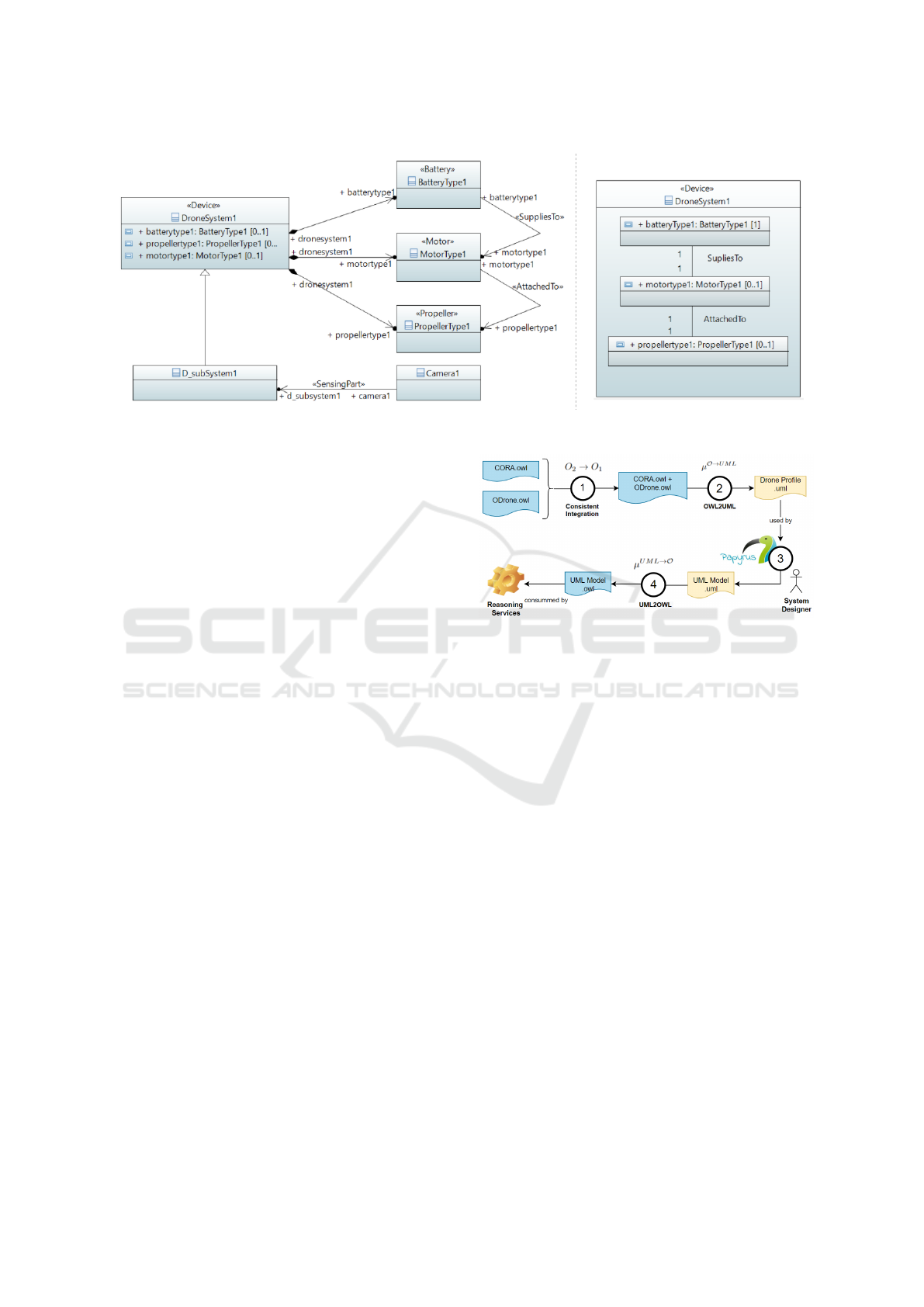
Figure 1: On the left, the UML Class Diagram for model M in example 4, on the right the Composite Structure Diagram for
DroneSystem1.
tool) and use UML Profiles to make the terminol-
ogy of the ontology available to the system’s designer.
The workflow is divided into four tasks, represented
by the circles in the diagram. The inputs and outputs
of these processes are depicted as color-coded files
with extension .oml (blue) or .uml (yellow). In the
following, we first explain the workflow and next, we
detail the construction of the mappings.
In Figure 2 on the top left we have two ontologies:
CORA.owl = O
1
and ODrone.owl = O
2
. ODrone.owl
is the Domain-Specific Ontology (Medinacelli et al.,
2022). This is the specific vocabulary used in the tar-
get domain of interest. Our implementation is en-
compassed within the autonomous systems domain,
and specifically the UAVs subdomain. The relevant
definitions in the domain-specific ontology need to
be mapped to UML. Specific ODrone concepts can
be asserted as specializations of UML classes, and
ODrone object and data properties can be asserted as
specializations of UML associations.
Task 1 outputs a consistent integration of O
2
into
O
1
, namely Union
O
2
,O
1
(see section 3). The union on-
tology Union
O
2
,O
1
consistently integrates the domain-
specific ontology ODrone into the upper and stan-
dardized ontology CORA. Thus providing a standard-
ized domain-specific ontology Union
O
2
,O
1
. Task 2
maps concepts and roles from Union
O
2
,O
1
to a UML
profile thanks to the mapping specification µ
O→UML
,
making the ontology semantics available to the sys-
tem designer in the MBSE tooling.
Indeed, the profile can now be used to model a sys-
tem in task 3. Thus it is the system designer who ap-
plies the mapping µ
O→UML
to a specific UML model
M. Once the annotated model is ready, the application
of the ”inverse” mapping µ
UML→O
takes place in task
4. This process yields O
UML
, an ODrone/OWL com-
pliant representation of the UML system, from where
Figure 2: The workflow and resources for the implementa-
tion of the approach.
a system specification T
UML
and a system instance
A
UML
can be obtained. The translated model O
UML
is suitable to be analyzed by reasoners. At this stage,
constraints expressed as queries (SPARQL), rules
(SWRL) or complex concept definitions (DL’s/OWL)
can be evaluated over the annotated UML model, in
the same manner as in (Medinacelli et al., 2022).
4.1 Mappings
To demonstrate the feasibility of the approach, we
have implemented a mapping between ODrone and
UML targeting: 1) Class Diagrams and 2) Composite
Structure Diagrams. In the literature (Mkhinini et al.,
2020), it is common to target Class Diagrams con-
structs due to its evident similarity with ontology con-
structs (e.g. classes, relations). Furthermore, Com-
posite Structure diagrams allow further specifying the
relations between the parts of a system. Using con-
structs in these two diagrams, the designer can de-
scribe the entities that play a role in his design, as
well as specific composite structures that carry inter-
connected parts.
In the ODrone implementation, we aim to de-
scribe the physical components of UAVs design,
that is, the parts of the system and how these are
A Methodology for Knowledge Integration and Acquisition in Model-Based Systems Engineering
269

interconnected. UML as well as ODrone, con-
sider a ”composition relation” named part. The
ODrone:hasPart object property’s meaning is analo-
gous to the uml::AggregationKind::composite prop-
erty. Both describe composition of complex struc-
tures by their parts. This correspondence between
ODrone and UML, is taken into account by algo-
rithm 1. It shows how to implement a mapping that
considers case-specific correspondences (between the
ontology and UML) and allows for the description of
complex composed UML structures using the ontol-
ogy concepts and relations. The output of algorithm 1,
is the restricted mapping µ
T
with which we can obtain
a system specification T
UML
. Whereas algorithm 2,
constructs the mapping µ
A
, which can be applied to
a UML model M to obtain a system instance A
UML
.
These two algorithms are presented next.
Recall:
µ
T
= {µ
⊑
, µ
≡
, µ
OP
, µ
DP
}
In algorithm 1 we first (1) initialize the sets
µ
⊑
, µ
≡
, µ
OP
, µ
DP
to be empty. Then for each
uml::Element in the model M (2) we verify if it is a (3)
uml::Class. Regardless of whether the uml::Class has
a stereotype (4), we add the pair ⟨uml :: Class, owl :
T hing⟩ to µ
⊑
, thus every uml::Class is mapped as
subclass of owl:Thing. Line (5) handles the case
of specialized classes, and in (9) we state that
each stereotyped class is subsumed by its stereo-
type. In line (11) we introduce the set CCD
E
=
{} (Complex Concept Description for E), this set
will be incrementally constructed to hold all stereo-
typed relations from the class (12-16), and all its
uml::CompositeAggregation (19-23) in the form of
a complex concept definitions. Note in line (22)
that each uml::CompositeAggregation is mapped to
odrone:hasPart. Thus relating a uml::Structure with
a domain-specific relation, existing only in ODrone.
Line (26) states that the pair ⟨E, CCD
E
⟩ belongs to
µ
≡
, effectively providing a complex concept defini-
tion for E, in terms of ODrone. Finally, in (29) a sub-
sumption relation is added to µ
OP
for each stereotyped
uml::Relationship. Note that this specific mapping al-
lows only for one stereotype per relation.
Let us now introduce the algorithm 2 to construct
the mapping µ
A
. Recall:
µ
A
= {µ
C(i)
, µ
r(a,b)
}
Algorithm 2 constructs the sets composing µ
A
, and
aggregates them into the output µ
A
. Algorithm 2 is
more straightforward, since we target only two UML
elements, both specializations of the same top ele-
ment uml::InstanceSpecification.
Input: M, µ
O→UML
Output: µ
T
1: µ
⊑
= µ
≡
= µ
OP
= µ
DP
= {}
2: for each uml::Element E ∈ M do
3: if E isA uml::Class then
4: ⟨E, owl : T hing⟩ ∈ µ
⊑
5: if E specializaionOf B ∈ M then
6: ⟨E, B⟩ ∈ µ
⊑
7: end if
8: for each E.AppliedStereotypes S ∈ M do
9: ⟨E, S⟩ ∈ µ
⊑
10: end for
11: CCD
E
= {}
12: for each E.getRelationships R ∈ M do
13: if R isA uml::Association and
R.AppliedStereotypes ̸=
/
0 then
14: b= R.target
15: S= R.AppliedStereotype
16: CCD
E
= CCD
E
⊓ {∃S.b}
17: end if
18: end for
19: for each E.getOwnedElements OE ∈ M do
20: if OE isA uml::CompositeAggregation
then
21: b= OE.getType
22: S= odrone:hasPart
23: CCD
E
= CCD
E
⊓ {∃S.b}
24: end if
25: end for
26: ⟨E, CCD
E
⟩ ∈ µ
≡
27: end if
28: end for
29: if E isA uml::Relationship and
|E.AppliedStereotypes|= 1 then
30: S= R.AppliedStereotype
31: ⟨E, S⟩ ∈ µ
OP
32: end if
33: return µ
T
= {µ
⊑
, µ
≡
, µ
OP
, {}}
Algorithm 1: Construction of µ
T
.
In algorithm 2 we first (1) initialize the sets
µ
C(i)
, µ
r(a,b)
to be empty. Then for each uml::Element
in the model M (2) we verify if it is a (3)
uml::InstanceSpecification. The way UML assigns a
class to an instance is through its classifiers. Lines (4-
7) state that for every classifier C of an instance E, the
pair ⟨E, C(E)⟩ belongs to the set µ
C(i)
. Note that this
process allows for multiple classifiers for the same in-
stance, which is intended in OWL. In the case where
an instance has no classifier (for example an anony-
mous individual which just participates in a relation)
line (9) assigns to instance E the most general concept
in CORA, i.e. cora : Entity. If it is the case the ele-
ment E is an instance specification of a relationship
KEOD 2023 - 15th International Conference on Knowledge Engineering and Ontology Development
270

Input: M, µ
O→UML
Output: µ
A
1: µ
C(i)
= µ
r(a,b)
= {}
2: for each uml::Element E ∈ M do
3: if E isA uml::InstanceSpecification then
4: if E.GetClassifiers ̸= {} then
5: for each E.GetClassifiers C ∈ M do
6: ⟨E, C(E)⟩ ∈ µ
C(i)
7: end for
8: else
9: ⟨E,cora:Entity(E)⟩ ∈ µ
C(i)
10: end if
11: if E isA uml::Relationship then
12: source= a
13: target= b
14: ⟨E, E(a, b)⟩ ∈ µ
r(a,b)
15: end if
16: end if
17: end for
18: return µ
A
= {µ
C(i)
, µ
r(a,b)
}
Algorithm 2: Construction of µ
A
.
(11), we obtain (12) the source a and (13) target b of
the relation, and state that ⟨E, E(a, b)⟩ ∈ µ
r(a,b)
. Note
that only stereotyped relations are captured. Once µ
A
and µ
T
are constructed, we can apply them to an UML
model M, to automatically obtain T
UML
and A
UML
.
These artifacts can be reused by new designs, or ex-
ploited by external tools and services that are com-
patible with ODrone and CORA, thus effectively al-
lowing the system designer to extend the ontology via
UML.
5 CONCLUSIONS
Our approach tackled two main problems: the avail-
ability and integration of domain-specific ontologies
into MBSE; and the capture and formalization of
knowledge from the expert’s design.
We have provided an end-to-end solution for the
integration of formal vocabularies into MBSE tool-
ing, effectively enabling the system designer to de-
scribe its system in terms of the ontology. This inte-
gration provides the context for other viewpoints and
stakeholders to interact. We have formally defined the
components a mapping from the terminology of an
ontology, to UML and back should consider (encoded
in OWL/UML format). This specification aims to en-
sure that the application of the mappings is consistent
w.r.t. the domain-specific ontology. Furthermore, by
clearly defining a system specification as a T-Box and
a system instance as an A-Box, we separate these two
aspects of system design, and we enable logic-based
techniques (like reasoning or SAT solving) to evaluate
and generate models for these artifacts.
As further work, we aim to enable the integration
of different ontologies, different system design tools
(e.g. safety, simulation, etc.), and to explore model
generation for the obtained specifications.
REFERENCES
Atkinson, C. and Kiko, K. (2005). A detailed comparison
of uml and owl. None.
Baader, F. (2003). Appendix: description logic terminology.
The Description logic handbook: Theory, implemen-
tation, and applications, pages 485–495.
Baader, F., Calvanese, D., McGuinness, D., Patel-
Schneider, P., Nardi, D., et al. (2003). The description
logic handbook: Theory, implementation and applica-
tions. Cambridge university press.
Baader, F., Horrocks, I., Lutz, C., and Sattler, U. (2017). In-
troduction to description logic. Cambridge University
Press.
Berardi, D., Calvanese, D., and De Giacomo, G. (2005).
Reasoning on uml class diagrams. Artificial intelli-
gence, 168(1-2):70–118.
Elasri, H. and Sekkaki, A. (2013). Semantic integration pro-
cess of business components to support information
system designers. arXiv preprint arXiv:1302.1393.
Hallberg, N., Jungert, E., and Pilemalm, S. (2014). Ontol-
ogy for systems development. International journal
of software engineering and knowledge engineering,
24(03):329–345.
Medinacelli, L. P., Noyrit, F., and Mraidha, C. (2022).
Augmenting model-based systems engineering with
knowledge. In Proceedings of the 25th International
Conference on Model Driven Engineering Languages
and Systems: Companion Proceedings, pages 351–
358.
Mezhuyev, V. (2014). Ontology based development of do-
main specific languages for systems engineering. In
2014 International Conference on Computer and In-
formation Sciences (ICCOINS), pages 1–6. IEEE.
Mkhinini, M. M., Labbani-Narsis, O., and Nicolle, C.
(2020). Combining uml and ontology: An exploratory
survey. Computer Science Review, 35:100223.
Parreiras, F. S. (2011). Marrying model-driven engineering
and ontology technologies: The twouse approach.
Vanherpen, K. e. a. (2016). Ontological reasoning for con-
sistency in the design of cyber-physical systems. In
2016 1st International Workshop on Cyber-Physical
Production Systems (CPPS), pages 1–8. IEEE.
Yang, L., Cormican, K., and Yu, M. (2019). Ontology-based
systems engineering: A state-of-the-art review. Com-
puters in Industry, 111:148–171.
A Methodology for Knowledge Integration and Acquisition in Model-Based Systems Engineering
271
