
Variable Trust Setting for Safe and Ethical Algorithms for
Navigation of Autonomous Vehicles (C-NAV) on a Highway
Joshua D’Souza, Jisun Kim and James E. Pickering
College of Engineering and Physical Science, Aston University, U.K.
Keywords: Control Engineering, Autonomous Vehicles, Model-Predictive Control (MPC), Navigation Algorithms,
Ethics, Vehicle Safety.
Abstract: This paper presents the use of an ethical model-to-decision approach for promoting safe manoeuvrability of
autonomous vehicles (AVs) on highways, when considering scenarios such as exiting a highway via a slip
road. In this research, a modelling and simulation approach is undertaken. The modelling involves the use of
an adaptive model-predictive control (MPC) algorithm with a dynamic bicycle model. The approach was
developed to incorporate a novel continuous evaluation of the distances between AVs (considering virtual
boundaries), logical sequences towards achieving safe lane change and slip road exit manoeuvres (driving
rules based on deontological ethics), and control logic towards accounting for acceleration, deceleration, and
constant velocity. Based on this, a novel continuous risk assessment algorithm has been developed based on
the product of collision probability and harm. This has been used to investigate the introduction of a novel
trust setting that gives the user ‘control’ of how the AV operates around other AVs. The results presented in
the paper highlight the effectiveness of the approach, i.e., the ability to undertake ethical and safe manoeuvres
in the event of difficult highway decision scenarios such as slip road exits.
1 INTRODUCTION
In recent years there have been significant
developments in the field of autonomous vehicles
(AVs). Recent improvements in communication
technology and computational power have meant that
AVs are now a possibility in the future to enhance
safety and improve efficiency of operation when
compared to human-driven vehicles (HDVs), see
(Bajpai, 2016) and (Taibat, et al., 2018). However,
the replacement of HDVs with AVs on the roads
introduces questions regarding how they should act in
given scenarios, e.g., performing a lane change to exit
at a junction. For example, should the AV perform
manoeuvres in a selfish manner to minimise journey
time? It is considered that such an approach would
increase the risk of a collision. Or should the AV
operate based on ‘if’ and ‘then’ commands in a
respectable manner to other road users? This
approach is typical of the behaviour of a human
operator of a vehicle, resulting in minimising the risk
of a collision. Such a scenario introduces questions of
just how an AV should be programmed. These
questions involve the investigation of safety and
ethical considerations, thus ensuring that AV
navigation planning decisions are justifiable and
reasonable. With the transition from HDVs to
autonomous driving, safety validation of the intended
functionality now becomes a key challenge due to the
uncertainty of the diving environment, see (Pettersson
and Karlsson, 2015). Simulations can be used to
explore novel navigation algorithms as they are safer
and less expensive, see (Koopman and Wayner, 2016)
and (Kalra and Paddock, 2016). Determining how an
AV will perform in simulation is an important step as
it enables different navigation algorithms to be
explored and any potential defects to be highlighted
and considered at the design stage.
In this paper, simulation tools will be used to
investigate the deontological ethical principles of
Immanuel Kant for AV navigation on a highway, with
the initial approach being developed by the authors,
see (Pickering et al., 2018), (Gilbert et al., 2021)
(D’Sousa, Burnham and Pickering, 2022) and
(Pickering and D’Souza, 2023). In this paper, further
considerations will be given to developing a novel
continuous evaluation risk tool for highway driving.
This is based on estimating the collision probability
and harm, in a similar manner to the approach
developed in (Geisslinger, Poszler and Lienkamp,
88
D’Souza, J., Kim, J. and Pickering, J.
Variable Trust Setting for Safe and Ethical Algorithms for Navigation of Autonomous Vehicles (C-NAV) on a Highway.
DOI: 10.5220/0012235900003543
In Proceedings of the 20th International Conference on Informatics in Control, Automation and Robotics (ICINCO 2023) - Volume 1, pages 88-96
ISBN: 978-989-758-670-5; ISSN: 2184-2809
Copyright © 2023 by SCITEPRESS – Science and Technology Publications, Lda. Under CC license (CC BY-NC-ND 4.0)

2023). In the paper by Geisslinger et al., 2023, the
authors developed novel trajectory planning
algorithms based on the EU commission expert
groups ‘20 recommendations’, with the aim of the
research being to fairly distribute risk amongst the
road users in the immediate vicinity. As part of this,
the authors developed a risk evaluation tool for
driving scenarios (note that the highway scenario was
not considered in their research). In (Németh, B.,
2023), the author has developed a coordinated control
approach using model predictive control (MPC) for
ethical manoeuvres of AVs – a similar approach is
used in this research.
The research in this paper is based on work
undertaken on the Safe and Ethical Algorithms for
Navigation of Autonomous Vehicles (C-NAV)
project and aims to support the Research Strategy
(published 19 August 2022) by the UK Government,
(Responsible Innovation in Self-Driving Vehicles,
2022).
2 BASELINE MODEL
A dynamic bicycle model is incorporated to represent
an AVs motion within the constructed coordinate
framework, see Figure 1. The two vectors denoted 𝑉
and 𝑉
represent the longitudinal and lateral
velocities, respectively. The path followed by the AV
depends on a reference trajectory denoted 𝑌
. The
reference trajectory is generated by setting the input
as the steering angle, denoted 𝛿. The two variables,
lateral position, denoted 𝑌
and yaw angle
reference, denoted 𝜑
are determined with respect
to the horizontal axis, denoted 𝑋 − axis , 𝜓 denotes
the yaw angle, 𝑙
denotes the longitudinal distance
from the center of gravity to the front tyres and 𝑙
denotes the longitudinal distance from the centre of
gravity to the rear tyres.
Figure 1: Reference trajectory control of a dynamic bicycle
mode.
2.1 Adaptive Model Predictive Control
An adaptive MPC algorithm is used, see Figure 2. For
brevity, details of the adaptive MPC and the model
parameters are not given in this paper. However, full
details can be found in (Melda, 2023). For the
adaptive MPC, a dynamic state-space bicycle model
adopted from (Rajamani, 2011) is given by the
following form:
𝑑
𝑑𝑡
𝑦
𝜓
𝜓
𝑌
=𝐴
𝑦
𝜓
𝜓
𝑌
+
⎣
⎢
⎢
⎢
⎢
⎡
2𝐶
𝑚
0
2𝑙
𝐶
𝐼
0
⎦
⎥
⎥
⎥
⎥
⎤
𝛿 (1)
where,
𝐴=
⎣
⎢
⎢
⎢
⎢
⎡
−
0−𝑉
−
0
00 1 0
0−
0
1𝑉
00
⎦
⎥
⎥
⎥
⎥
⎤
Figure 2: Adaptive model predictive control (MPC).
Considering the input to the system to be the steering
angle, the objective of adaptive MPC is to minimise
the deviation of the lateral displacement and the yaw
angle of the AV. Considering vehicle performance
and passenger comfort, the maximum steering angle
and steering rate are capped at 30 degrees and 15
degrees per second, respectively.
2.2 Highway Scenario
In this section, a two-axis coordinate system is used
for the highway, see Figure 3. The AVs on the
highway are denoted 𝐴𝑉
and 𝐴𝑉
, with these located
in Lanes 1 and 2, respectively, 𝑉
and 𝑉
denote the
respective resultant velocities, (𝑥
, 𝑦
) and (𝑥
, 𝑦
)
denote the lateral and longitudinal positions measured
from origin 0 (0, 0), respectively.
In this paper, the highway scenario is given in
Figure 4, with the corresponding way points for 𝐴𝑉
Variable Trust Setting for Safe and Ethical Algorithms for Navigation of Autonomous Vehicles (C-NAV) on a Highway
89

and 𝐴𝑉
(further details regarding the simulation are
given in later sections), where 𝐴𝑉
remains in Lane 1
and 𝐴𝑉
performs an overtake manoeuvre on 𝐴𝑉
to
enable exit at the slip road.
Figure 3: Two-dimensional coordinate system of the
highway setup.
Figure 4: Highway scenario with each of the autonomous
vehicle’s (AV’s) way points.
3 RISK ASSESSMENT
In this Section, a collision risk assessment model is
developed to quantify the risk associated with the
interaction between the two AVs. The risk assessment
is given by Equation (2):
𝑅
=𝑃
(
𝑐
)
𝐻
(2)
where 𝑅
denotes the risk assessment, which is
continuously updated during the simulation, 𝑃(𝑐)
denotes the probability of a collision and 𝐻
denotes
the harm index. Further details regarding Equation (2)
are given in the following sections. The risk
assessment is set-up such that a value of 0
corresponds to a risk-free situation and a value of 1
corresponds to a high-risk situation, i.e., high
likelihood of a collision event.
3.1 Virtual Boundaries
To ensure safe manoeuvrability of the AVs, use is
made of ‘barrier’ and ‘buffer’ virtual boundaries. The
barrier zone is denoted 𝐵
and the buffer zone is
denoted 𝐵
, see Figure 5. The barrier of each AV
must not be entered by another AV. However, the
buffer of each AV can be entered but it must be left
as soon as possible. The boundaries are set up on each
AV from their centre of gravity (CG) such that the
barrier length, denoted 𝑙
, spans out from 𝑙
and
𝑙
from the fore (front) and aft (rear) directions of
the AVs heading, respectively, and between 𝑙
and
𝑙
from the left to the right of the AV, respectively.
The following values are used for the barrier: 𝑙
=
10𝑚, 𝑙
=10m 𝑙
=1𝑚 and 𝑙
=1𝑚. The
buffer length, denoted 𝑙
similarly spans out at
distances of 𝑙
, 𝑙
, 𝑙
and 𝑙
from the centre
of gravity for the fore, aft, left and right of the AV’s
heading, respectively. The following values are used
for the buffer: 𝑙
=20𝑚, 𝑙
=20m 𝑙
=2𝑚
and 𝑙
=2𝑚.
Figure 5: Virtual boundary of an autonomous vehicle (AV).
3.2 Collision Probability
For two AVs in motion, the probability of a collision,
denoted 𝑃(𝑐), is dependent on the longitudinal
Buffer (𝐵
)
Barrier (𝐵
)
𝐴
𝑉
𝐴
𝑉
ICINCO 2023 - 20th International Conference on Informatics in Control, Automation and Robotics
90

separation distance, denoted ∆𝑦
, and lateral
separation distance, denoted ∆𝑥
between the two
vehicles, i.e.,
𝑃
(
𝑐
)
=
𝑓
(∆𝑥
,∆𝑦
)
(3)
If the virtual boundaries are respected (i.e., no overlap
of their respective barriers), the probability of a
collision is 0. To this extent, the initial values for the
barrier virtual boundaries are set up for the risk
assessment model for each AV that are considered to
be safe, i.e., ∆𝑥
=4𝑚 (considering the sides of
the two AVs) and ∆𝑦
=40𝑚 (considering the
front and rear of each AV), where ∆𝑥
and ∆𝑦
denote safety benchmark values for lateral and
longitudinal separation between two AVs,
respectively.
On this basis, the probability of a collision can be
derived to be proportional to the ratio of the measured
separation distances to their respective benchmark
values. Hence, the following equation can be derived
as the collision probability calculation for the
developed risk assessment model:
𝑃
(
𝑐
)
=1 −
∆𝑥
∆𝑥
1 −
∆𝑦
∆𝑦
(4)
3.3 Collision Harm Index
In addition to calculating collision probabilities,
another important factor that defines the severity of a
potential collision involves mapping the potential
harm that is associated with a given action. In this
section, harm is quantified by the collision energy in
each scenario. This is modelled by considering the
law of conservation of momentum and energy for a
two-vehicle inelastic collision, with these being given
by:
𝑚
𝑣
+ 𝑚
𝑣
=𝑚
𝑣
(5)
where 𝑚
and 𝑚
denote the masses of 𝐴𝑉
and
𝐴𝑉
, respectively, 𝑣
and 𝑣
denote the collision
velocities of 𝐴𝑉
and 𝐴𝑉
, respectively. Considering
the post-collision AV properties, 𝑚
denotes the
combined AV masses and 𝑣
denotes the final
velocity of the combined AVs. Based on Equation
(5), the conservation of energy for an inelastic two-
vehicle collision is given by:
1
2
𝑚
𝑣
+
1
2
𝑚
𝑣
=
1
2
𝑚
+ 𝑚
𝑣
+ ∆𝐸
(6)
where ∆𝐸 denotes the collision energy between the
two AVs. Based on Equation (6), the Harm Index is
derived, and is given by:
𝐻
=
∆𝐸
(𝑡)
∆𝐸
(7)
where ∆𝐸
denotes the actual collision energy
between the two AVs and ∆𝐸
denotes the
maximum possible collision energy between the two
AVs. The Harm Index is dimensionless where the
values vary between 0 and 1, where 0 corresponds to
a collision that would cause the least harm under the
given circumstance, i.e., the least possible collision
energy. A value of 1 corresponds to the collision that
would result in the greatest amount of harm, i.e., the
highest possible collision energy. In this case, since
the mass of the AVs are constant, ∆𝐸
depends on
the maximum possible velocity at which the
overtaking vehicle can travel at on the highway, i.e.,
70 𝑚𝑝ℎ (or alternatively 31.29 𝑚/𝑠).
4 SIMULATION SET-UP
This section details the mathematical considerations
required to achieve the desired driving manoeuvres
whilst incorporating the safe and ethical conditions.
4.1 Lane Change
In this case, 𝐴𝑉
is considering a lane changing
manoeuvre to position itself in front of 𝐴𝑉
.
Considering the driving rules and the virtual
boundaries, a lane change is a direct result of always
maintaining respect of the boundary zones, see
(Pickering and D’Souza, 2023). This requires a
continuous evaluation of both AVs. To
mathematically capture such requirements, the
following equations describe the longitudinal, lateral,
and resultant separation distances:
𝑦
=𝑦
− 𝑦
(8)
𝑥
=𝑥
− 𝑥
(9)
𝑅
=
(𝑦
+ 𝑥
)
(10)
where 𝑦
denotes the longitudinal separation between
the two AVs, 𝑥
denotes the lateral separation between
the two AVs and 𝑅
denotes the resultant separation.
Maintaining the same objective of respecting the
boundaries, it is therefore desired that there are no
overlaps between the boundaries of the two AVs. This
is achieved with consideration of the following:
Variable Trust Setting for Safe and Ethical Algorithms for Navigation of Autonomous Vehicles (C-NAV) on a Highway
91

𝑦
(
𝑡+ ∆𝑡
)
=𝑦
(
𝑡+ ∆𝑡
)
+𝑙
+𝑙
(11)
𝑦
𝑙
+𝑙
(12)
where 𝑡 denotes the time, ∆𝑡 denotes the time
required to complete a lane change, 𝑙
denotes
the front portion of 𝐴𝑉
barrier and 𝑙
denotes
the aft (rear) portion of 𝐴𝑉
barrier. Equation (11) is
derived such that 𝐴𝑉
clears the barrier of 𝐴𝑉
after
the lane change is achieved, whilst maintaining the
respect of the boundaries longitudinally; with this
forming the lane change Constraint 1. Equation (12)
is adopted to ensure that the boundaries are not
violated laterally at the start and during the phase of
the lane changing manoeuvres. Hence, 𝐴𝑉
is
constrained to initiating the manoeuvre only when a
longitudinal separation of the sum of the front portion
of 𝐴𝑉
’s barrier and the rear portion of 𝐴𝑉
barrier,
with this forming the second constraint for a ‘safe’
lane change.
4.2 Slip Road Entry
This section will detail the constraints in place for the
slip road exit. Considering the driving rules and the
virtual boundaries, the first slip road entry (i.e.,
exiting the highway) constraint involves 𝐴𝑉
longitudinal displacement of 700 𝑚. To further
enhance the safety aspects, it is important to ensure
that 𝐴𝑉
does not undertake any dangerous actions,
i.e., suddenly changing directions without
considering the virtual boundaries.
4.3 Adaptive Velocity Control
For 𝐴𝑉
to be able to perform the overtaking move
into Lane 1 ahead of 𝐴𝑉
, the velocities of the two AVs
will need to be altered, i.e., 𝐴𝑉 accelerating or
decelerating to increase or decrease velocity. This
section details the modelling required to capture the
𝐴𝑉’s acceleration and deceleration properties. A
logical sequence is required to be implemented to
establish when the AV needs to accelerate, decelerate,
or maintain a constant velocity. MATLAB Stateflow
logic is used for this, see Figure 6. The inputs to the
logic are the lateral position of 𝐴𝑉
, individual
longitudinal displacements of both 𝐴𝑉𝑠, and the
longitudinal separation between the two AVs. The
Stateflow chart is defined for 𝐴𝑉
to initially accelerate
to 31.29 𝑚/𝑠 (70𝑚𝑝ℎ) from its starting velocity. This
is then maintained until a safe lane change has occurred
alongside a safe slip road entry, with the AV then
decelerating to the initial velocity. This results in a 4-
stage velocity control process involving: acceleration,
constant velocity, deceleration, and constant velocity.
Figure 6: Flowchart illustrating control logic of an adaptive
velocity control.
4.4 Simulation Logic
Figure 7 illustrates a flowchart containing the AVs
decision making logic/algorithm. The logic is set up
to comprise of 6 major stages, with these being:
i. Stage 1 involves the incorporation of
longitudinal and lateral displacements of the
two AVs, involving continuous evaluation
of the two-vehicles relative displacement.
ii. Stage 2 is setup to test the validity of the first
lane change constraint, determining whether
virtual boundaries would be respected after
the lane change manoeuvre. If obeyed, this
builds onto Stage 3.
iii. Stage 3 tests the validity of lane change
Constraint 2. A negative result from Stage 3
deems this to be an ‘unsafe’ lane change
manoeuvre.
iv. Conversely, achieving the constraint set in
Stage 3 results in ensuring that a safe lane
changing manoeuvre can be undertaken,
leading to the input of the lane change
reference trajectory in Stage 4, placing 𝐴𝑉
in lane 1, i.e., Constraint 2 for a safe slip road
entry.
v. Stage 5 undertakes a comparison study,
determining whether a longitudinal
displacement of 700 𝑚 is achieved, i.e.,
longitudinal location of the slip road. If the
comparison study is positive, a slip road
entry is deemed to be safe, which results in
the slip road entry reference trajectory input.
vi. Procedure successful.
ICINCO 2023 - 20th International Conference on Informatics in Control, Automation and Robotics
92

Figure 7: Flowchart illustrating the simulation logic.
5 RESULTS
A scenario is detailed in this section to highlight the
operation of the developed algorithms.
5.1 Deontological Ethics Example
The scenario in the results section is set such that both
AVs (i.e., 𝐴𝑉
and 𝐴𝑉
) are of equal masses and start
off at the same longitudinal displacement and initial
velocity, as detailed in Table I. Table I also details the
initial lateral displacement, initial lane position and
the desired lane position.
Table 1: Input parameters for scenario 1.
𝑨𝑽
𝒂
𝑨𝑽
𝒃
Mass [kg] 1575 1575
Initial velocity
[m
p
h]
60 60
Initial longitudinal
dis
p
lacement [m]
0 0
Initial longitudinal
displacement [m]
-4 0
Initial lane
p
osition Lane 1 Lane 2
Desired lane
p
osition
Lane Lane 1 and slip
road entr
y
The adaptive MPC algorithm presented in Section 2.2
is now simulated with the properties given in Table I.
The initial results of this section are also given in an
earlier paper published by the authors, see (Pickering,
D’Souza, 2023). Initially two AVs are simulated
using way points given in Figure 4. For the
simulation, 𝐴𝑉
in the left-hand lane will travel at a
constant velocity of 60 𝑚𝑝ℎ (26.82 𝑚/𝑠). The
velocity of the overtaking AV (i.e., 𝐴𝑉
) will alter
based on obeying the driving ethical rules are obeyed,
such that 𝐴𝑉
does not enter the ‘barrier’ virtual
boundary of 𝐴𝑉
. Figure 4 also illustrates the highway
simulation scenario of the two AVs, with the way
points and the 10 corresponding iterations of the
simulation, i.e., from 0 seconds to 28.8 seconds.
5.2 Risk Assessment Example
A simulation is now given using the scenario detailed
in Section 5.1 involving the risk assessment.
However, in this example the reference trajectory
input (i.e., way points) for the adaptive MPC for a
lane change manoeuvre (i.e., for 𝐴𝑉
) is applied. This
change is applied to demonstrate a scenario whereby
the risk assessment is used. For the example given in
Section 5.1, this resulted in a peak risk assessment
value of 0.23, i.e., both AVs are at low risk of a
collision.
Figures 8 and 9 illustrate the lateral separation
versus time and longitudinal separation versus time
between the between AVs, respectively for the
scenario given in Figure 4.
Figure 8: Deontological ethics initial results: lateral
separation versus time for the two autonomous vehicles.
Figure 9: Deontological ethics initial results: longitudinal
separation versus time for the two autonomous vehicles.
Considering the result obtained in Figure 4 (and the
zoomed in area), 𝐴𝑉
performs a lane changing
manoeuvre that results in the overlap of the virtual
boundaries of the two AVs during that phase, i.e., the
buffer zone. However, the barrier for each of the AVs
Variable Trust Setting for Safe and Ethical Algorithms for Navigation of Autonomous Vehicles (C-NAV) on a Highway
93
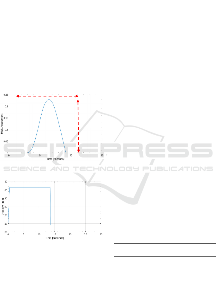
is respected. The result of the risk assessment for this
scenario is given in Figure 10. In Figure 10, the
journey initial starts off as a risk-free journey.
However, based on the logic applied in the
simulation, 𝐴𝑉
begins to perform the lane changing
manoeuvre once the barrier zone is passed. However,
this results in the AVs entering into one another’s
buffer zones. In Figure 10, the peak risk assessment
(PRA) and duration of risk imposed (DRI) values are
labelled, where values of 0.23 and 6.38 seconds are
captured, respectively. The risk assessment does not
last for a long duration due to the adaptive velocity
control of 𝐴𝑉
, with this resulting in 𝐴𝑉
travelling at
a velocity of 70𝑚𝑝ℎ when overtaking 𝐴𝑉
, and then
returning to the initial velocity of 60𝑚𝑝ℎ once passed
𝐴𝑉
, see Figure 11.
Figure 10: Graphical output illustrating the risk versus time
generated.
Figure 11: Adaptive velocity control output.
5.3 Variable Trust Setting
Trust is an important element for occupants of AVs
due to the likelihood of entering into vulnerable
situations whereby the occupant entrusts in the
system (Körber, Baseler and Bengler, 2018). Trust
can have an impact on the occupant’s decision to use
the automation (Lee and Moray, 1994). Trust is
defined as the “willingness of a party to be vulnerable
to the actions of another party based on the
expectation that the other will perform a particular
action important to the trustor, irrespective of the
ability to monitor and control that other party”
(Mayer, Davis, and Schoorman, 1995). For there to
be trust in the automation, the multifaceted construct
that embraces performance, process, purpose, and
foundation must be established. Performance is
related to consistency, stability and desirability of
automation. Process indicates operators’ knowledge
of the underlying algorithms that govern behaviour of
the system. Purpose represents the producers’
intention in creating the system (Lee and Moray,
1992).
Considering the risk assessment example in
Section 5.2, this is now used in the development of a
variable trust setting. A setting of 0% implies no trust
in the AV technology and 100% implies complete
trust in the AV technology, with this setting based on
the user preference. Varying the level of trust of the
AV will result in varying the distance of the barrier
element of the virtual boundaries, with the values
used in this paper given in Table II. Recall from
Section 3.0 that another AV should not enter into
another AVs barrier (an overtake will take place once
the barrier has been passed).
The model is now used to investigate the effect of
the variable trust settings given in Table II. Figure 12
illustrates the risk assessment results for a range of
variable trust settings, where the PRA and DRI values
are labelled. The key findings from Figure 12 relating
to the PRA and DRI are given in Table III. Based on
the findings, these are as expected, i.e., when the
barrier length reduces the risk assessment (i.e., risk
exposed to the occupants) increases.
Table 2: Variable trust setting in percentage and linguistic
terms relating to the virtual boundaries.
Variable
Trust Setting
[0 – 100%]
Linguistic
terms
Virtual Boundaries
𝒎
Barrier Buffer
0 No trust 12 20
25 Little trust 11 20
50 Medium
trust
10 20
75 Medium
to high
trust
9 20
100 Complete
trust
8 20
PRA
DRI
ICINCO 2023 - 20th International Conference on Informatics in Control, Automation and Robotics
94

Figure 12: Longitudinal displacement versus time of the
autonomous vehicle compared to the reference.
Table 3: Variable trust setting in percentage and the
corresponding results for peak risk assessment (PRA) and
duration of risk imposed (DRI).
Variable Trust
Setting [0 –
100%]
Peak Risk
Assessment
(PRA)
Duration of
Risk Imposed
(DRI) [Seconds]
0 0.19 5.88
25 0.21 6.18
50 0.23 6.38
75 0.25 6.58
100 0.26 6.78
6 CONCLUSIONS AND
FURTHER WORK
This paper has presented a novel approach towards
enhancing safe and ethical manoeuvrability of
autonomous vehicles (AVs) on highways. Regarding
the safe and ethical decision-making strategies, the
paper has considered driving rules with Maxims
based on deontological ethics and coupled with the
application of AV virtual boundaries. An adaptive
model predictive control (MPC) algorithm alongside
the incorporation of a dynamic bicycle model is used
to model each AV and achieve the desired
trajectories. The paper also proposes a novel
methodology for a continuous risk evaluation
algorithm that is based on collision probabilities
between the two AVs. It has been demonstrated how
a risk assessment can be used as part of a novel
variable trust setting onboard an AV, with the
following observations/findings. Increasing the
variable trust setting from 0 to 100% (with this
reducing the barrier of the virtual boundaries) results
in an increased peak risk assessment (PRA) value and
an increased duration of risk imposed (DRI). Based
on this initial finding, it is believed the variable trust
setting would allow users of an AV to feel more in
control (via the variable trust setting knob), allowing
the user to explore the technology more (thus, helping
to build confidence and better acceptance of the
technology), thus allowing for a more comfortable
ride through perceived increased safety of AVs
Whist promising results were obtained, there is
scope for much further work. Further work would
involve considering a dynamically changing
environment to further enhance a realistic approach to
the modelling. The use of a high-fidelity propriety
tool such as CarMaker would also be beneficial as it
would enable implementing the developed algorithms
in real time.
REFERENCES
Bajpai, J.N. Emerging vehicle technologies & the search for
urban mobility solutions, Urban, Planning and
Transport Research, vol. 4, no. 1, pp. 83–100, 2016.
D’Souza, J., Burnham, K. J., Pickering, J. E. (2022).
Modelling and Simulation of an Autonomous Vehicle
Ethical Steering Control System (ESCS). International
Conference on Methods and Models in Automation and
Robotics (MMAR). Miedzyzdroje: Institute of
Electrical and Electronics Engineers (IEEE).
Geisslinger, M., Poszler, F. and Lienkamp, M., 2023. An
ethical trajectory planning algorithm for autonomous
vehicles. Nature Machine Intelligence, pp.1-8.
Gilbert, Alex, Dobrila Petrovic, James E. Pickering, and
Kevin Warwick. "Multi-attribute decision making on
mitigating a collision of an autonomous vehicle on
motorways." Expert Systems with Applications 171
(2021): 114581.
Lee, J. and Moray, N., 1992. Trust, control strategies and
allocation of function in human-machine systems.
Ergonomics, 35(10), pp.1243-1270.
Lee, J.D. and Moray, N., 1994. Trust, self-confidence, and
operators' adaptation to automation. International
journal of human-computer studies, 40(1), pp.153-184.
Mayer, R.C., Davis, J.H. & Schoorman, F.D. 1995, "An
integrative model of organizational trust", Academy of
management review, vol. 20, no. 3, pp. 709-734.
Melda Ulusoy (2023). Designing an MPC controller with
Simulink (https://www.mathworks.com/matlabcentral/
fileexchange/68992-designing-an-mpc-controller-with
-simulink), MATLAB Central File Exchange.
Retrieved February 28, 2023.
Németh, B., 2023. Coordinated Control Design for Ethical
Maneuvering of Autonomous Vehicles. Energies,
16(10), p.4254.
Kalra., N and Paddock, S. M. Driving to safety: How many
miles of driving would it take to demonstrate
autonomous vehicle reliability? Transportation
PRA
DRI
Variable Trust Setting for Safe and Ethical Algorithms for Navigation of Autonomous Vehicles (C-NAV) on a Highway
95

Research Part A: Policy and Practice, vol. 94, pp. 182–
193, 2016.
Körber, M., Baseler, E. and Bengler, K., 2018. Introduction
matters: Manipulating trust in automation and reliance
in automated driving. Applied ergonomics, 66, pp.18-
31.
Koopman, P., and Wagner, M. Challenges in autonomous
vehicle testing and validation, SAE International
Journal of Transportation Safety, vol. 4, no. 1, pp. 15–
24, 2016.
Pettersson, I. and Karlsson, I.M. (2015), Setting the stage
for autonomous cars: a pilot study of future autonomous
driving experiences. IET Intell. Transp. Syst., 9: 694-
701. https://doi.org/10.1049/iet-its.2014.0168
Pickering, J. E., and D’Souza, J., 2023. Deontological
Ethics for Safe and Ethical Algorithms for Navigation
of Autonomous Vehicles (C-NAV) on a Highway. 9TH
International Conference on Control, Decision and
Information Technologies, July 03 - 06 2023, Rome,
Italy.
Pickering, J.E., Ashman, P., Gilbert, A., Petrovic, D.,
Warwick, K. and Burnham, K.J., 2018, September.
Model-to-decision approach for autonomous vehicle
convoy collision ethics. In 2018 UKACC 12th
International Conference on Control (CONTROL) (pp.
301-308). IEEE.
Rajamani, R., 2011. Vehicle dynamics and control.
Springer Science Business Media
Responsible Innovation in Self-Driving Vehicles, 2022.
Centre for Data Ethics and Innovation, UK.
Taiebat, M., and Brown, H. R. Safford, Qu, S., and Xu, M.
A review on energy, environmental, and sustainability
implications of connected and automated vehicles,
Environmental science & technology, vol. 52, no. 20,
pp. 11 449–11 465, 2018.
ICINCO 2023 - 20th International Conference on Informatics in Control, Automation and Robotics
96
