
2D LiDAR-Based Human Pose Tracking for a Mobile Robot
Zhenyu Gao
a
, Ze Wang, Ludovic Saint-Bauzel
b
and Fa
¨
ız Ben Amar
c
Sorbonne University, CNRS, UMR 7222, Institut des Systemes Intelligents et Robotique - ISIR, France
Keywords:
Human Detection and Tracking, Human Orientation Estimation, Service Robotics.
Abstract:
Human pose tracking is a practical feature for service robots, which allows the robot to predict the user’s
trajectory and behavior and thus provide appropriate assistance for them. In this paper, we propose a human
pose tracking method based on a knee-high 2D LiDAR mounted on the mobile robot. Inspired by human gait,
a motion intention zoning, and a walking gait model are proposed to adapt to various motion patterns and
achieve accurate orientation estimation. We propose a Kalman Filter-based human pose tracker that considers
the leg occlusion problem and the data association of legs. We evaluate the proposed method’s performance
in various complex scenarios and demonstrate robustness to leg occlusion. We released our implementation as
open-source code
∗
.
1 INTRODUCTION
Mobile robots have become more prevalent in every
corner of our lives: shopping malls, hospitals, lo-
gistics warehouses, factories, homes, and many oth-
ers. Many tasks in these applications are still shared
between robots and human operators, either because
human expertise or agility is required or because the
robot can assist the person. In this paper, we are in-
terested in the interaction between a mobile robot and
a human, particularly in the automatic pose tracking
of the person by the mobile robot. In previous studies,
common human tracking approaches obtain the user’s
position or pose through sensors with distance infor-
mation such as RGB-D cameras and/or 2D LiDAR
(Jung et al., 2012)(Ho et al., 2012)(Hu et al., 2013).
Among them, 2D LiDAR is more widely used for hu-
man tracking due to the larger field of view (FOV), ro-
bust light adaptability, and excellent accuracy. Some
2D LiDAR-based methods for extracting human posi-
tion from the 2D raw point clouds have already been
proposed. Usually, the point cloud is first segmented
by clustering, e.g., density-based spatial clustering
(DBSCAN) (Hasan et al., 2021), heuristic clustering
(Zhao and Shibasaki, 2005)(Chung et al., 2011), and
simple distance segmentation (Leigh et al., 2015)(Lee
a
https://orcid.org/0000-0002-6141-806X
b
https://orcid.org/0000-0003-4372-4917
c
https://orcid.org/0000-0002-4590-3452
∗
The code is available at https://github.com/SyRoCo-
ISIR/Frontal human following
et al., 2006). Clusters are then identified as humans or
other objects according to their different contours in
the point cloud. Some classifiers such as Bayesian
classifier (Tamas et al., 2010), Support Vector Data
Description (SVDD) (Chung et al., 2011)(Jung et al.,
2013) and Adaptive boosting (Adaboost) (Arras et al.,
2008)(Mozos et al., 2010) have been implemented to
label clusters by their geometric features, spatial fea-
tures, etc. Besides, a Convolutional Neural Network
(CNN) has been adapted instead of clustering and
classifiers, input with 2D (Guerrero-Higueras et al.,
2019) or 3D (Br
ˇ
s
ˇ
ci
´
c et al., 2020) raw point clouds and
output the target labels and positions.
Besides human identification and position track-
ing, research on human orientation is increasingly
in demand. Some specific services require mobile
robots to come in front of users. For example, as-
sistive robots act like guide dogs to provide naviga-
tion aid to the visually impaired (Xiao et al., 2021),
and smart walkers provide walking assistance to peo-
ple with mobility impairments (Lee et al., 2013)(Page
et al., 2015). Some studies have shown that people
prefer to see the robots in their field of vision and
may feel uncomfortable and unsafe when the robots
appear behind them (Jung et al., 2012). For some so-
cial robots, being in front of the user will facilitate
communication with him/her. Human orientation es-
timation has been widely studied for frontal human
following, where the most common method is based
on human velocity direction. (Ho et al., 2012) de-
fined the velocity direction as the sagittal axis and im-
Gao, Z., Wang, Z., Saint-Bauzel, L. and Ben Amar, F.
2D LiDAR-Based Human Pose Tracking for a Mobile Robot.
DOI: 10.5220/0012255600003543
In Proceedings of the 20th International Conference on Informatics in Control, Automation and Robotics (ICINCO 2023) - Volume 1, pages 511-519
ISBN: 978-989-758-670-5; ISSN: 2184-2809
Copyright © 2023 by SCITEPRESS – Science and Technology Publications, Lda. Under CC license (CC BY-NC-ND 4.0)
511

plemented an Unscented Kalman Filter (UKF) with a
non-holonomic human movement model to improve
human pose estimation. A spin turn observer was ap-
plied to deal with spin turns. Based on the human
pose, the controller kept the robot in front of the hu-
man and aligned it to the same orientation as the hu-
man. (Nikdel et al., 2018) also assumed the human
velocity direction as the sagittal axis. They set up an
Infinite Impulse Response (IIR) filter to smooth hu-
man velocity and orientation changes. A new human
motion model based on the surrounding environment
was proposed to improve human following perfor-
mance. Their recent study implemented Reinforce-
ment Learning (RL) (Nikdel et al., 2021) to output
short-time navigation goals and employed a Timed
Elastic Band (TEB) local planner to keep the robot
in front. However, humans are redundant and have a
lot of possible mobilities. Some specific human mo-
tion patterns, such as turn-in-place, lateral movement,
etc., are difficult to track by their method. Volunteers
performed simple and regular walking in the experi-
ment, but complex walking patterns were not verified.
In addition to velocity direction-based methods,
(Cifuentes and Frizera, 2016) proposed a method to
estimate human orientation using an Inertial Measure-
ment Unit (IMU) mounted on the pelvis. The human
position was obtained with a 2D LiDAR mounted at
knee height. They applied the gait cycle to improve
human pose tracking accuracy. Yet, the extra sensor
could cause inconvenience to the user. Certain meth-
ods employed the body shape in a 2D point cloud
to estimate the human orientation. (Shimizu et al.,
2016) took 2D LiDAR data at 36 viewpoints with 10
deg intervals to create the dataset. The human ori-
entation was calculated by comparing the point cloud
data observed in real time with the dataset collected.
A UKF tracker-based human motion information was
integrated to improve the estimation accuracy, called
the shape-motion integration approach. The mean ab-
solute error (MAE) of their method in human orienta-
tion estimation is 6
◦
−12
◦
when the robot was station-
ary, and the human performed simple motion. Simi-
larly, (Glas et al., 2009) assumed that the body shape
in the point cloud is a geometric shape consisting of
three circles to estimate human orientation. But these
methods are too influenced by body shape and cloth-
ing, etc. (Shorter et al., 2017) found that humans usu-
ally chose the metabolically optimal step width when
walking straight normally through experiments. The
swinging leg is almost in a straight line because the
circumduction requires much effort. Based on their
research, (Yorozu and Takahashi, 2020) hypothesized
that the sagittal axis is parallel to the velocity direc-
tion of the swing leg. A human walking model was
d
e
f
g
a
b
c
Figure 1: System Setup: (a) Target user to track, (b)
SUMMIT-XL with mecanum wheels, (c) Hokuyo URG-04-
LX-UG01 Laser Rangefinder, (d) Motion capture system,
(e) Reflective beads on the square structure, (f) Reflective
beads on the mobile robot, (g) Ground markings.
applied to determine the swing leg to track the human
orientation during normal walking. Their experiments
proved that their method is suitable for normal walk-
ing, such as going straight, turning, and U-turns. The
results showed an MAE of 6
◦
−14
◦
in human orienta-
tion. However, when the robot was in motion, the drift
of the robot’s pose would affect the human orientation
estimation. Noteworthy is that almost all of the above
methods do not consider human lateral movement.
In this article, we propose a human pose track-
ing method based on 2D LiDAR for mobile robots.
Our contribution includes three items. First, we im-
plement step-width-adapted human intention zoning
allowing various human motion patterns (including
lateral movement). Second, we integrate a simple
gait model to predict the relative position between the
legs. Finally, we propose a Kalman filter-based hu-
man pose tracker that addresses the problem of short-
time leg occlusion and data association of legs. Our
article is organized as follows: The section II presents
our platform and the four sub-modules of our system,
the section III shows the experimental results, and fi-
nally ends with a discussion and conclusion.
2 MATERIALS AND METHODS
2.1 Platform and System Overview
We use a high-mobility mobile robot developed by
Robotnik, Summit-XL (as shown in Fig. 1). It is
equipped with mecanum wheels for omnidirectional
movement on flat indoor floors and can reach a speed
of 3 m/s. Two 2D LiDARs (Hokuyo URG-04-LX-
UG01 Laser Rangefinder) with FOV of 180
◦
each are
ICINCO 2023 - 20th International Conference on Informatics in Control, Automation and Robotics
512

LiDAR
Leg detection
Orientation
estimation
Gait parameters
identification
Frontal human
following
Robot base
controller &
Odometry
+
-
Human tracking (10 Hz)
Human following (50 Hz)
Human orientation
Gait parameters
Point cloud
Legs' position
Velocity command
Robot pose
Relative position
Pose tracking
Human pose
Figure 2: System Overview Flowchart.
installed on the robot, about 40 cm above the ground.
One faces backward to detect the target user and the
environment behind, and the other faces forward to
detect obstacles ahead. SUMMIT-XL has an inte-
grated PC, enabling the communication between the
modules through the Robot Operating System (ROS)
(Quigley et al., 2009) architecture. The development
focuses on the human pose tracking, so an open en-
vironment with low complexity and few obstacles is
assumed. In addition, a frontal following function is
developed for the SUMMIT-XL, making it strive to
come in front of the user and always face the user.
The robot deals with obstacles through a safety func-
tion that stops the robot when it is close to an obstacle.
As shown in Fig. 2, the human tracking module con-
tains leg detection, human orientation estimation, gait
parameters identification and a pose tracker. It oper-
ates at 10 Hz depending on the sampling frequency of
the LiDAR. Then, the human following module plans
the robot’s motion, which is not the main focus of this
paper. The tasks of the human tracking module are
explained below.
Invisible right l
Robot 𝑆
Visible left leg
𝐿
W
0
𝑥
𝑦
𝑂
Invisible right leg
𝑅
Invisible
right l
𝑅
𝑜
Figure 3: Leg detection in a 2D point cloud: one user has
both legs visible and the other has one leg occluded.
2.2 Leg Detection
Leg detection is one of the most common methods
(Hasan et al., 2021)(Chung et al., 2011)(Leigh et al.,
2015)(Cifuentes and Frizera, 2016)(Yorozu and Taka-
hashi, 2020) in human tracking. Compared with body
detection, it contains rich gait information. The 2D
LiDAR mounted at the height of human lower limbs
publishes the 2D raw point cloud (Red scattered dots
in Fig. 3). The module then segments the point cloud
into several clusters by distance thresholding and ig-
nores the clusters with less than three total points to
avoid the effect of outliers. Since the contour of the
legs in the point cloud is two adjacent semicircles, the
module adopts nonlinear optimization to detect cir-
cles in these clusters. Three variables that determine
a circle need to be optimized: the circle center coor-
dinates (x,y) and the circle radius r. (x
i
,y
i
) represent
the position of each point in the cluster; there are a
total of n points. Given that the radius of a human leg
is around 0.05 m, the optimization problem adds a ra-
dius limit. The nonlinear optimization is solved with
the NLopt library (Johnson et al., 2014), to be precise,
the NLOPT LD MMA algorithm (Svanberg, 2002).
f
l
(x,y, r) =
n
∑
i=1
((x
i
− x)
2
+ (y
i
− y)
2
− r
2
)
2
min
x,y,r
f
l
(x,y, r)
s.t. 0.03 < r < 0.07
(1)
The leg detection module excludes some non-
circular clusters and obtains leg candidates. The mod-
ule initializes the pair of candidate legs most proxi-
mate to the robot as the target user. At the next mo-
ment, the search space is determined in the vicinity of
the target user to reduce unnecessary computation.
2D LiDAR-Based Human Pose Tracking for a Mobile Robot
513

𝑥
𝑦
𝜃
𝑚,𝑘
ℎ
𝑥
𝑚,𝑘
𝑙
, 𝑦
𝑚,𝑘
𝑙
𝑥
𝑚,𝑘
𝑟
, 𝑦
𝑚,𝑘
𝑟
𝑥
𝑚,𝑘
𝑟
, 𝑦
𝑚,𝑘
𝑟
𝜃
𝑘−1|𝑘−1
ℎ
𝜃
𝑚,𝑘
ℎ
𝜃
𝑚,𝑘
ℎ
𝜃
𝑚,𝑘
ℎ
𝜃
𝑚,𝑘
ℎ
𝑥
𝑚,𝑘
𝑟
, 𝑦
𝑚,𝑘
𝑟
𝑥
𝑚,𝑘
𝑟
, 𝑦
𝑚,𝑘
𝑟
𝑥
𝑚,𝑘
𝑟
, 𝑦
𝑚,𝑘
𝑟
𝑂
Move-sideways
Go-straight
Turn-in-place
Go-straight-slight-turn
Figure 4: Geometric human orientation estimation in motion intention zones : (Left) Stand still, (Middle) go-straight and
move-sideways, (Right) go-straight-slight-turn and turn-in-place.
2.3 Human Orientation Estimation
We propose a human motion intention zoning to esti-
mate the human orientation with the current legs’ po-
sition (x
l
m,k
,y
l
m,k
), (x
r
m,k
,y
r
m,k
), where k is the current
moment, m represents the measurement, and r and l
denote the left and right legs, respectively. The pre-
vious human orientation
ˆ
θ
h
k−1|k−1
is used as the base-
line, where h represents the body. As shown in Fig. 4,
the two-foot symbol icon represents legs and W indi-
cates the step width which is calculated by the pro-
jection of the vector between the legs on the human
frontal plane.
Based on the research of (Shorter et al., 2017), an
expanded hypothesis is proposed that the step width
(W = W
0
) remains almost constant when humans usu-
ally walk. However, the swinging leg is not entirely
in a plane parallel to the human sagittal plane during
walking, nor is the support leg. A specific interval of
step width is then allowed when going straight, which
forms the go-straight zone. The human orientation
estimation keeps constant in the go-straight zone, the
green area in Fig. 4 (Middle). However, when walk-
ing normally, humans often make slight turns while
maintaining the state of going straight. Slight turns
that do not require great human effort form the go-
straight-slight-turn zone (blue area). Fig. 4 (Right)
explains the geometric human orientation estimation
method in the go-straight-slight-turn zone. Based on
the assumption of constant human step width, we can
define two parallel lines separated by the constant step
width W
0
, passing through the two legs. The direction
of these two parallel lines is assumed to determine the
human orientation. In our zoning, the human moves
laterally when the leg swings perpendicular to the hu-
man sagittal plane. Like the go-straight zone, the zon-
ing introduces a move-sideways zone (the light red
area in Fig. 4) where the human orientation estima-
tion remains constant. The final yellow area is the
turn-in-place zone. As shown in Fig. 4 (Right), the
human sagittal plane is assumed to be perpendicu-
lar to the vector of the legs. The human orientation
increment in different zones is calculated geometri-
cally, which rotates the intention zoning. The current
pseudo human orientation θ
h
m,k
(the arrow between
legs) is then estimated as the measurement for the fol-
lowing Kalman Filter (KF).
The human motion intention zoning adapts to
users of various body sizes with different step widths.
The leg detection module automatically collects the
average distance between legs over a few seconds as
the default step width W
0
for the user when initializ-
ing the target user. Then, the corresponding human
motion intention zoning is auto-generated according
to the default step width. In addition, the move-
sideways and turn-in-place zone are considered not
usual for human motion, where the step width is vari-
able. Thus, the four zones are subdivided into usual
human motion with solid go-straight intention and un-
usual human motion with weak go-straight intention.
This will be employed for the prediction of leg posi-
tion in the human pose tracking.
ICINCO 2023 - 20th International Conference on Informatics in Control, Automation and Robotics
514

2.4 Gait Parameters Identification
The left and right legs swing periodically in the usual
human motion zones (green and blue areas). We as-
sume that the projection of the vector between the legs
on the human sagittal plane is a cosine function over
time. Equation (2) introduces the simple gait model
containing four gait parameters, which is sufficient for
predicting the relative position between the legs.
L
p
= L
0
cos(2π f t + ϕ) + b
(2)
L
p
denotes the projection of the vector between
the legs on the human sagittal plane, and L
0
is the
step length (or amplitude of the projection). Ca-
dence f is the rhythm of the human gait, i.e., the fre-
quency with which the legs cross one after the other.
Phase ϕ represents the current state in the gait cy-
cle. Offset b is around zero during the usual walk-
ing. When b suddenly increases or decreases, the hu-
man is out of the gait cycle. Thanks to the NLopt
library (Johnson et al., 2014) and, to be precise, the
NLOPT LN COBYLA algorithm (Powell, 1994), the
module obtains the real-time gait parameters by fitting
the historical data. The objective function is shown in
equation (3).
f
g
(L
0
, f ,ϕ,b) =
N
∑
j=1
w
j
(L
0
cos(2π f t
j
+ ϕ) + b − l
j
)
2
min
L
0
, f ,ϕ,b
f
g
(L
0
, f ,ϕ,b)
s.t. 0.1 < L
0
< 0.5
0.5 < f < 1.5
0 < ϕ < 2π
0 < b < 0.5
where w
j
= 1/ j
2
(3)
N represents the number of historical data frames
used. The optimization uses one gait cycle period,
about 2 seconds, i.e., 20 frames. j represents the
frame number, which is in reverse chronological or-
der. l
j
and t
j
denote the actual measurement of the
projection and the actual time at frame j, respectively.
w
j
is an inverse quadratic function defined as the
weighting between different moments. The older the
time, the lower the weight. This function gives bet-
ter results than using consistent weights and is more
delay-free for parameter identification, but any de-
clining function should work.
2.5 Human Pose Tracking
The pose tracking module is based on a Kalman Fil-
ter with a constant acceleration model. The state vec-
tor P includes the human pose H =
X
h
Y
h
θ
h
T
,
and his first and second-order derivatives. The state-
transition equation (4) is shown below.
P
k
=F
k
P
k−1
+ w
k
(4)
where
• State vector P
k
=
H
T
˙
H
T
¨
H
T
T
k
• State-transition model
F
k
=
I
3
∆tI
3
∆t
2
2
I
3
0
3,3
I
3
∆tI
3
0
3,3
0
3,3
I
3
,
Sampling time ∆t = 100ms,
3×3 Identity matrix I
3
, 3×3 Zero matrix 0
3,3
• Process noise w
k
∼ N (0, Q
k
)
We employed a discrete process noise model in
which (X
h
,Y
h
,θ
h
) are considered to be independent
of each other so that most of the terms in the matrix
Q
k
are zero. We assume that the white noise of the
acceleration (
¨
X
h
,
¨
Y
h
,
¨
θ
h
) is zero mean with variance
(σ
2
ax
,σ
2
ay
,σ
2
aθ
). In the experiments, the variance pa-
rameters were set as (10
2
,10
2
,π
2
).
For the measurements, the human position
(X
h
m,k
,Y
h
m,k
) is calculated by averaging the positions of
both legs detected by the leg detection module. The
human orientation θ
h
m,k
is obtained by the orientation
estimation algorithm f
o
in section 2.3. The measure-
ment equation (5) is shown below.
z
k
=M
k
P
k
+ v
k
(5)
where
• Measurements
z
k
=
h
x
l
m,k
+x
r
m,k
2
y
l
m,k
+y
r
m,k
2
f
o
i
T
• Measurement model M
k
=
I
3
0
3,3
0
3,3
• Measurement noise v
k
∼ N (0, C
k
)
Similarly, the measurements are considered in-
dependent. Hence, the measurement noise ma-
trix C
k
is diagonal, where (σ
2
X
,σ
2
Y
,σ
2
θ
) is equal to
(0.03
2
,0.03
2
,(π/15)
2
), respectively.
Since leg detection does not label each leg mea-
sured, the data association problem exists when track-
ing the human, i.e., matching the legs’ measurements
of the next moment (x
l
m,k+1
,y
l
m,k+1
),(x
r
m,k+1
,y
r
m,k+1
)
with the predictions of the current moment
(x
l
k+1|k
,y
l
k+1|k
),(x
r
k+1|k
,y
r
k+1|k
). The linear model
KF can only predict the human pose and cannot
determine the position of the legs. The human motion
intention zoning, which contains the legs’ spatial
relationship, is adopted for further legs’ predictions.
In zones where humans usually walk with solid
go-straight intention (green and blue areas), the
2D LiDAR-Based Human Pose Tracking for a Mobile Robot
515

gait model is applied to predict the relative position
between legs (∆x
k+1|k
,∆y
k+1|k
). For unusual motion
with weak go-straight intention (light red and yellow
areas), the legs’ predictions are supposed to be
symmetrical concerning the human sagittal plane.
Combining the human pose predicted by KF
ˆ
P
k+1|k
,
the position of both legs at the next moment is
estimated. The Nearest Neighbor (NN) approach is
used to match the two arriving measurements of legs
and to distinguish between the left and right legs.
One leg obstructing the other is a common oc-
clusion problem during human following. The oc-
cluded leg is spatially constrained behind the visible
leg. Since the two legs cannot be far apart, the pos-
sible area of the occluded leg is heuristically defined
as the hidden area behind the visible leg. The green
trapezoidal area, as shown in Fig. 3, is the hidden area
of the right leg. The center of this area R
o
= (x
r
o
,y
r
o
)
was defined at one step width W
0
outside the exten-
sion of the robot S = (X
s
m,k+1
,Y
s
m,k+1
) and the visible
left leg L = (x
l
m,k+1
,y
l
m,k+1
).
⃗
OR
o
=
⃗
OS +
⃗
SR
o
=
⃗
OS + (
W
0
∥
⃗
SL∥
+ 1)
⃗
SL
(6)
The right leg prediction R
k+1|k
= ( ˆx
r
k+1|k
, ˆy
r
k+1|k
) is
attracted by the center of hidden area R
o
. The longer
the occlusion duration T
o
, the more distorted the pre-
diction is and the more confidence from spatial con-
straints. Consequently, the attraction grows with the
rise of occlusion duration. For implementation details
refer to equation (5).
⃗
OR
k+1|k+1
= α
⃗
OR
k+1|k
+ (1 − α)
⃗
OR
o
where α =
1
e
T
o
(7)
The confidence of model prediction α gradually
converges to 0 as the occlusion duration T
o
increases.
In the absence of one measurement, the improved
prediction is used as the system’s measurement input
while increasing the input’s variance.
3 EXPERIMENT AND RESULTS
Twelve volunteers (nine men and three women) par-
ticipated in the experiment. In order to be respectful
of the Helsinki Declaration, they were fully informed
of the data collection and its purpose. They were also
informed that they could leave the experience any-
time. They were also informed that they could ask
for access, modification, and deletion of the collected
data anytime. They were having an emergency stop
in the hand in order to avoid any hazard. The exper-
iments were carried out in a room equipped with the
Motion Capture system for ground truth, as shown in
Fig. 1. We had considered mounting reflective beads
on the body, but since there were only four cameras in
the room, the beads were easily occluded, and mea-
surements were lost. To avoid occlusion of the beads
for the MoCap system, volunteers hold a sufficiently
wide square structure flat against their chests during
experiments. The reflective beads were installed on
the structure and mobile robot to capture their trajec-
tories (ground truth) in an inertial frame. Considering
the degree of the waist, the orientation of the upper
body and lower body can be different, such as facing
towards the left front but going forward. Therefore,
during the experiments, we asked the volunteers con-
trol their waist immobility to keep the same upper and
lower body orientation. Each naive volunteer had 30
minutes preparation period to get used to the robot’s
following function and to understand how the robot
works. The volunteers then had another 30 minutes to
try four scenarios:
• Scenario 1: Go straight forward, make a 55
◦
right
turn, and then back up
• Scenario 2: Move sideways to the right, make a
180
◦
turn, and then move sideways to the left
• Scenario 3: Make a 90
◦
right turn and then go
straight forward immediately
• Scenario 4: Perform a random movement
To show the experimental results in detail, the first
volunteer is taken as an example. Fig. 5 presents a
comparison of his orientation estimation and ground
truth in the four scenarios. Table 1 contains his orien-
tation tracking MAE in both cases with and without
occlusion processing, and position tracking MAE on
both frontal and sagittal axes in the case with occlu-
sion processing.
In Scenario 1, the first volunteer kept his upper
body facing forward and advanced naturally two me-
ters, but a slight rotation of the pelvis was unavoid-
able while walking. Likewise, his orientation oscil-
lated periodically in small amplitudes (≈ 8
◦
) under
MoCap. Our tracking module detected this small am-
plitude oscillation, and the estimated orientation was
somewhat more stable than the actual value due to the
step width interval. The volunteer then turned to the
right (≈ 55
◦
), where the estimation was slightly de-
layed (≈ 0.4 s). However, the overall trend of the
orientation was tracked by our system. Finally, the
volunteer moved backward two meters, similarly, ori-
entation oscillation was observed here as well. In
general, our tracking module maintained good track-
ing, showing an MAE of about 2.3
◦
. Distinguished
ICINCO 2023 - 20th International Conference on Informatics in Control, Automation and Robotics
516
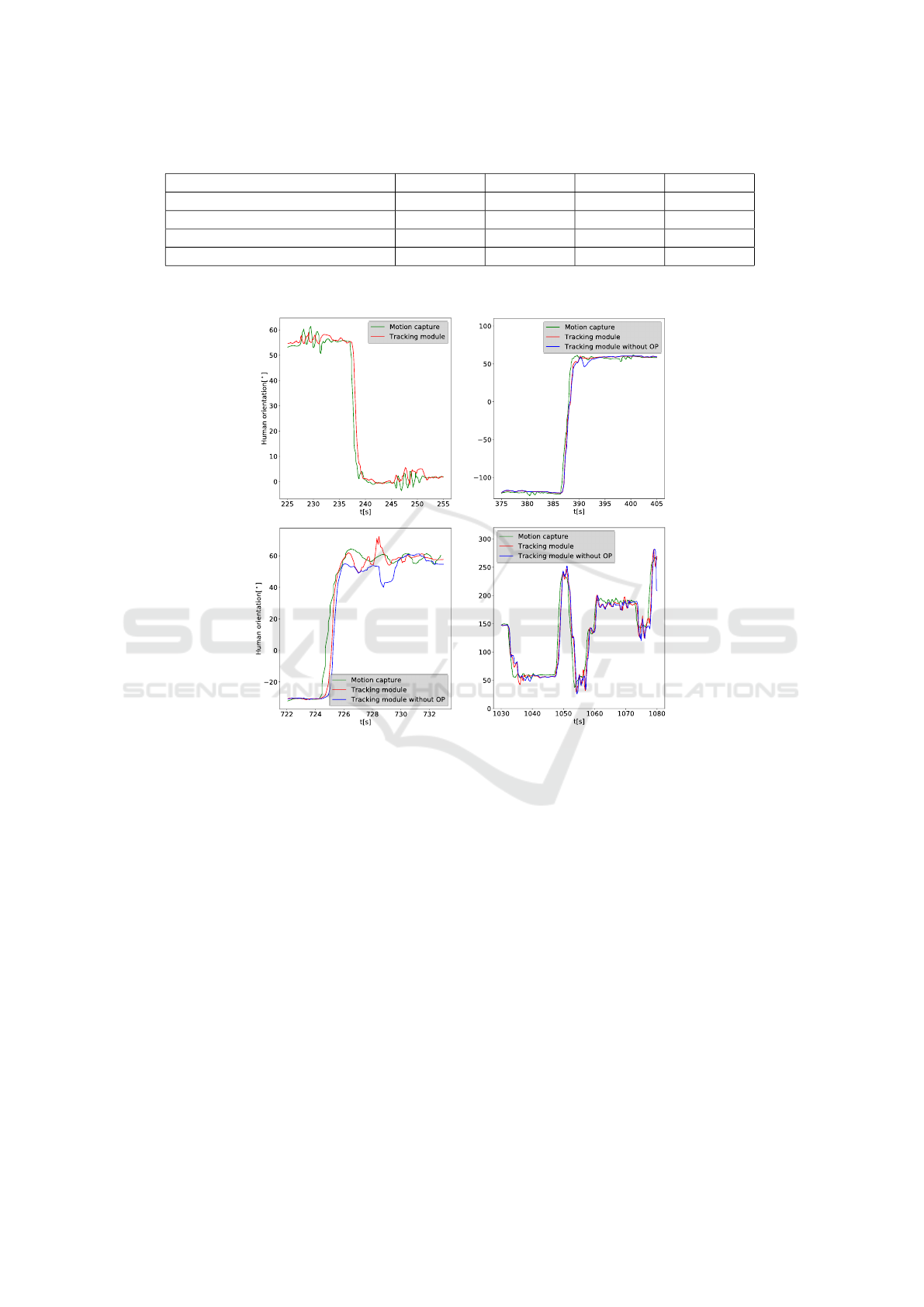
Table 1: Tracking MAE for the first volunteer.
Tracking MAE Scenario 1 Scenario 2 Scenario 3 Scenario 4
In orientation (
◦
)
∗
2.3 ± 3.9 4.1 ± 6.8 7.0 ± 9.7 14.0 ± 17.5
In orientation (
◦
) 2.3 ± 3.9 3.2 ± 6.3 4.1 ± 6.7 11.5 ± 13.6
In position on the frontal axis (m) 0.15 ± 0.14 0.26 ± 0.30 0.29 ± 0.23 0.40 ± 0.37
In position on the sagittal axis (m) 0.38 ± 0.59 0.1 ± 0.08 0.27 ± 0.23 0.45 ± 0.42
∗
Only this row corresponds to the tracking module without occlusion processing
Scenario 1
Scenario 2
Scenario 3 Scenario 4
Figure 5: Human tracking performance for the first volunteer; Four figures show the comparison of human orientation under
motion capture and under human tracking module with/without Occlusion Processing (OP).
by motion patterns, the MAE was about 2
◦
in the for-
ward and backward phases and about 7
◦
in the turning
phase.
For Scenario 2, the volunteer held the upper body
forward and shifted one meter to the right, and then he
turned 180
◦
in place in about 2 s. The tracking module
did a delay during the turning phase but kept tracking
and did not reverse the human’s frontal plane (i.e., the
left and right legs were incorrectly correlated). Addi-
tionally, there was a case where one leg was occluded
by the other during the turning phase. For compari-
son, we activated two sets of human tracking modules
at the same time: one without occlusion processing
(blue curve in Fig. 5) and the other with occlusion
processing (red curve). This processing improved the
tracking performance and decreased the overall track-
ing MAE by 0.9
◦
(see Table 1). The tracking pre-
sented an MAE of about 3.2
◦
in scenario 2, about 2
◦
during lateral moves, and about 10
◦
during significant
turning.
In Scenario 3, the volunteer turned quickly 90
◦
to
the right and went straight ahead; the tracking mod-
ule showed a slight delay during the turning phase but
the occlusion processing reduced the delay. In the for-
ward phase, the robot was to the side of the user, so
the right leg was often occluded by the left leg. The
occlusion processing significantly reduced the overall
tracking MAE by 2.9
◦
.
Scenario 4 is challenging, with volunteers mov-
ing randomly in an open room. The tracking module
kept tracking him, but not as well as in the previous
scenarios, with an MAE of about 11.5
◦
. This sce-
nario illustrates the robustness of our system, which
can adapt to most human motion patterns, as well as
random combinations of different patterns.
In general, the experiment with all 12 volunteers
2D LiDAR-Based Human Pose Tracking for a Mobile Robot
517

proceeded satisfactorily, with MAEs ranging in 2
◦
−
12
◦
for the four scenarios. This also proves that our
system adapted to the users’ step widths.
4 DISCUSSION
The experimental results show that our system ac-
complishes the pose tracking for twelve volunteers.
A slight delay (< 0.6 s) in orientation tracking is no-
ticed when humans make a turn. We think this delay
may be due to human turning habits, where humans
usually turn the upper body before the lower body.
Therefore, the orientation ground truth from the chest
would be a little earlier than our tracking module from
the legs. Although the volunteers were told to keep
the upper and lower body synchronized during the ex-
periment, there was a slight error in the ground truth.
Furthermore, the delay may come from go-straight
and move-sideways intervals. The interval setting
avoids over-sensitivity of the human orientation to
leg position changes and introduces delay simultane-
ously. By adapting to the step width, our system ini-
tially accommodates the differences due to body size
and walking habits. For better tracking performance,
our system requires users not to wear robes, not to
jump above the detection plane, not to stand with legs
crossed, not to run at high speed, etc. Compared to
current state-of-the-art methods (Cifuentes and Friz-
era, 2016)(Nikdel et al., 2021)(Yorozu and Takahashi,
2020), our tracker considers human lateral movement
as well as the occlusion of one leg during walking.
This brings us the advantage of pose tracking accu-
racy. Compared with (Yorozu and Takahashi, 2020),
we estimate orientation using the relative position be-
tween the legs, independent of robot pose drift, which
is especially suitable for highly mobile robots. In
terms of experimental design, unlike most studies that
adopted simple scenarios, we designed complex sce-
narios that encompassed most motion patterns. No-
tably, challenging and adapting to the random walk is
also our distinct advantage.
5 CONCLUSION
In this paper, we developed a robust step-width-
adapted human pose tracker based on 2D LiDAR. We
have dealt with diverse walking patterns, the prob-
lem of self occlusion of legs, and data association
when tracking. We performed a quantitative analysis
of the system’s performance using experimental data
and identified some existing limitations. The track-
ing function functioned robustly in all scenarios, even
when the user moved randomly.
We will attempt a data-driven method to estimate
human pose in addition to this gait-inspired method.
We expect to expand on the human pose tracker with
new contactless human-robot interaction possibilities,
such as frontal human following, navigation for the
visually impaired, logistics in automated warehouses,
and social robots in shopping malls. Furthermore, im-
proving physical human-robot interaction by utilizing
human pose is also a direction we will work on.
ACKNOWLEDGEMENTS
This work has been partially supported by ROBOTEX
2.0, the French Infrastructure in Robotics under the
grants ROBOTEX (EQUIPEX ANR-10-EQPX-44-
01) and TIRREX (EQUIPEX+ grant ANR-21-ESRE-
0015). Zhenyu Gao was sponsored by the China
Scholarship Council.
REFERENCES
Arras, K. O., Grzonka, S., Luber, M., and Burgard, W.
(2008). Efficient people tracking in laser range data
using a multi-hypothesis leg-tracker with adaptive oc-
clusion probabilities. In 2008 IEEE International
Conference on Robotics and Automation, pages 1710–
1715. IEEE.
Br
ˇ
s
ˇ
ci
´
c, D., Evans, R. W., Rehm, M., and Kanda, T. (2020).
Using a rotating 3d lidar on a mobile robot for esti-
mation of person’s body angle and gender. Sensors,
20(14):3964.
Chung, W., Kim, H., Yoo, Y., Moon, C.-B., and Park, J.
(2011). The detection and following of human legs
through inductive approaches for a mobile robot with
a single laser range finder. IEEE transactions on in-
dustrial electronics, 59(8):3156–3166.
Cifuentes, C. A. and Frizera, A. (2016). Human-robot inter-
action strategies for walker-assisted locomotion, vol-
ume 115. Springer.
Glas, D. F., Miyashita, T., Ishiguro, H., and Hagita, N.
(2009). Laser-based tracking of human position and
orientation using parametric shape modeling. Ad-
vanced robotics, 23(4):405–428.
Guerrero-Higueras,
´
A. M.,
´
Alvarez-Aparicio, C.,
Calvo Olivera, M. C., Rodr
´
ıguez-Lera, F. J.,
Fern
´
andez-Llamas, C., Rico, F. M., and Matell
´
an, V.
(2019). Tracking people in a mobile robot from 2d
lidar scans using full convolutional neural networks
for security in cluttered environments. Frontiers in
neurorobotics, 12:85.
Hasan, M., Hanawa, J., Goto, R., Fukuda, H., Kuno, Y., and
Kobayashi, Y. (2021). Person tracking using ankle-
level lidar based on enhanced dbscan and optics. IEEJ
ICINCO 2023 - 20th International Conference on Informatics in Control, Automation and Robotics
518

transactions on electrical and electronic engineering,
16(5):778–786.
Ho, D. M., Hu, J.-S., and Wang, J.-J. (2012). Behavior
control of the mobile robot for accompanying in front
of a human. In 2012 IEEE/ASME International Con-
ference on Advanced Intelligent Mechatronics (AIM),
pages 377–382. IEEE.
Hu, J.-S., Wang, J.-J., and Ho, D. M. (2013). Design of
sensing system and anticipative behavior for human
following of mobile robots. IEEE Transactions on In-
dustrial Electronics, 61(4):1916–1927.
Johnson, S. G. et al. (2014). The nlopt nonlinear-
optimization package.
Jung, E.-J., Lee, J. H., Yi, B.-J., Park, J., Noh, S.-T.,
et al. (2013). Development of a laser-range-finder-
based human tracking and control algorithm for a
marathoner service robot. IEEE/ASME transactions
on mechatronics, 19(6):1963–1976.
Jung, E.-J., Yi, B.-J., et al. (2012). Control algorithms
for a mobile robot tracking a human in front. In
2012 IEEE/RSJ International Conference on Intelli-
gent Robots and Systems, pages 2411–2416. IEEE.
Lee, G., Ohnuma, T., Chong, N. Y., and Lee, S.-G. (2013).
Walking intent-based movement control for jaist ac-
tive robotic walker. IEEE Transactions on Systems,
Man, and Cybernetics: Systems, 44(5):665–672.
Lee, J. H., Tsubouchi, T., Yamamoto, K., and Egawa, S.
(2006). People tracking using a robot in motion with
laser range finder. In 2006 IEEE/RSJ International
Conference on Intelligent Robots and Systems, pages
2936–2942. Ieee.
Leigh, A., Pineau, J., Olmedo, N., and Zhang, H. (2015).
Person tracking and following with 2d laser scanners.
In 2015 IEEE international conference on robotics
and automation (ICRA), pages 726–733. IEEE.
Mozos, O. M., Kurazume, R., and Hasegawa, T. (2010).
Multi-part people detection using 2d range data. In-
ternational JOURNAL of social robotics, 2:31–40.
Nikdel, P., Shrestha, R., and Vaughan, R. (2018). The
hands-free push-cart: Autonomous following in front
by predicting user trajectory around obstacles. In 2018
IEEE International Conference on Robotics and Au-
tomation (ICRA), pages 4548–4554. IEEE.
Nikdel, P., Vaughan, R., and Chen, M. (2021). Lbgp: Learn-
ing based goal planning for autonomous following
in front. In 2021 IEEE International Conference on
Robotics and Automation (ICRA), pages 3140–3146.
IEEE.
Page, S., Martins, M. M., Saint-Bauzel, L., Santos, C. P.,
and Pasqui, V. (2015). Fast embedded feet pose esti-
mation based on a depth camera for smart walker. In
2015 IEEE International Conference on Robotics and
Automation (ICRA), pages 4224–4229. IEEE.
Powell, M. J. (1994). A direct search optimization method
that models the objective and constraint functions by
linear interpolation. Springer.
Quigley, M., Conley, K., Gerkey, B., Faust, J., Foote, T.,
Leibs, J., Wheeler, R., Ng, A. Y., et al. (2009). Ros: an
open-source robot operating system. In ICRA work-
shop on open source software, volume 3, page 5.
Kobe, Japan.
Shimizu, M., Koide, K., Ardiyanto, I., Miura, J., and
Oishi, S. (2016). Lidar-based body orientation esti-
mation by integrating shape and motion information.
In 2016 IEEE International Conference on Robotics
and Biomimetics (ROBIO), pages 1948–1953. IEEE.
Shorter, K. A., Wu, A., and Kuo, A. D. (2017). The high
cost of swing leg circumduction during human walk-
ing. Gait & posture, 54:265–270.
Svanberg, K. (2002). A class of globally convergent opti-
mization methods based on conservative convex sepa-
rable approximations. SIAM JOURNAL on optimiza-
tion, 12(2):555–573.
Tamas, L., Popa, M., Lazea, G., Szoke, I., and Majdik, A.
(2010). Lidar and vision based people detection and
tracking. JOURNAL of Control Engineering and Ap-
plied Informatics, 12(2):30–35.
Xiao, A., Tong, W., Yang, L., Zeng, J., Li, Z., and Sreenath,
K. (2021). Robotic guide dog: Leading a human
with leash-guided hybrid physical interaction. In 2021
IEEE International Conference on Robotics and Au-
tomation (ICRA), pages 11470–11476. IEEE.
Yorozu, A. and Takahashi, M. (2020). Estimation of body
direction based on gait for service robot applications.
Robotics and Autonomous Systems, 132:103603.
Zhao, H. and Shibasaki, R. (2005). A novel system
for tracking pedestrians using multiple single-row
laser-range scanners. IEEE Transactions on systems,
man, and cybernetics-Part A: systems and humans,
35(2):283–291.
2D LiDAR-Based Human Pose Tracking for a Mobile Robot
519
