
Longitudinal Motion Control of Underactuated Cruising AUVs for
Acoustic Bottom Survey
Kangsoo Kim
a
National Maritime Research Institute, National Institute of Maritime, Port and Aviation Technology,
6-38-1 Shinkawa, Mitaka, Tokyo 181-0004, Japan
Keywords: Longitudinal Motion Control, Acoustic Bottom Survey, Cruising AUV, Underactuated, Depth Control,
Bottom Following.
Abstract: Longitudinal motion control approaches for underactuated cruising AUVs primarily tasked with acoustic
bottom surveys are addressed. For controlling the longitudinal motion of a cruising AUV, we implemented
waypoint-based depth control and terrain following approaches during simulated acoustic bottom survey
missions. Simulation results revealed that the distinct motion control approaches significantly influence the
pitch motion of the vehicle, thereby directly impacting the quality of the acoustic bottom survey results. The
safety issue of a cruising AUV, particularly regarding the occurrence of bottom collisions during its near-
bottom survey missions is also investigated in this research. Concerning the safety issue, we found that while
traversing the same trackline, the likelihood of an AUV encountering a bottom collision varies considerably,
based on the specific motion control approach being utilized.
1 INTRODUCTION
Conducting high-definition bottom surveys is a
pivotal task encompassing a diverse range of ocean
development endeavours, with particular significance
in the exploration of submerged natural resources like
marine minerals, offshore oil, and gas. Preceding the
essential bottom samplings in the conclusive phase of
surveys targeting these resources, a high-definition
bottom mapping or imaging is imperative. In the
realm of underwater exploration of such purposes, the
Autonomous Underwater Vehicle (AUV) assumes a
vital role. It facilitates the acquisition of bottom
survey data with considerably higher definition
compared to what can be obtained through surface
vessels (Honsho et al., 2015; 2016). In regard to
acoustic bottom surveys, nowadays, bottom mapping
sonars like Multi-Beam Echo Sounder (MBES) or
Interferometry Sonar (IFS) have achieved widespread
utilization in AUV-based high-definition seabed
surveys (Ferrini et al., 2007; Kim et al., 2023). In the
context of acoustic bottom mapping, it is widely
recognized that the angular motion of a mapping
sonar typically has a significant impact on the
accuracy of mapping results. More specifically, it is
a
https://orcid.org/0000-0003-1496-4145
well known that excessive pitch or roll motion
significantly degrades the quality of acoustic bottom
mapping (Cobra et al., 1992; Kim et al., 2023).
Based on their behavioural characteristics, AUVs
are typically categorized into two groups: cruising or
flight-class AUVs, and hovering AUVs (Lea et al.,
1999; Houts et al., 2012). While a hovering AUV has
the capability to remain stationary and manoeuvre
around a specific operational point, the majority of
cruising AUVs lack this ability. This arises from the
fact that the majority of cruising AUVs are
underactuated, which means they possess fewer
actuators than the degrees of freedom (DOF) they
need to control (Spong, 1998; Tedrake, 2009).
Underactuation results in certain degrees of freedom
becoming uncontrollable, thereby limiting the path-
following capability of underactuated systems.
Hence, it is easy to envision that a cruising AUV
inherently faces challenges when it comes to evading
imminent collisions with nearby obstacles (Pedbody,
2008; Kim et al. 2023). In terms of the vehicle
dynamics, the underactuation presents itself as the
coupled vehicle motion. Within the framework of the
longitudinal dynamics of a cruising AUV, for
example, heave and pitch motions are strongly
754
Kim, K.
Longitudinal Motion Control of Underactuated Cruising AUVs for Acoustic Bottom Survey.
DOI: 10.5220/0012257200003543
In Proceedings of the 20th International Conference on Informatics in Control, Automation and Robotics (ICINCO 2023) - Volume 1, pages 754-762
ISBN: 978-989-758-670-5; ISSN: 2184-2809
Copyright © 2023 by SCITEPRESS – Science and Technology Publications, Lda. Under CC license (CC BY-NC-ND 4.0)
coupled. Consequently, whenever a cruising AUV
alters its vertical position, a concurrent pitch motion
invariably accompanies. In case a cruising AUV flies
over a flat and uniform seafloor without a specific
objective, it does not need to alter its vertical position
with respect to the surface, that is, its depth. In
general, however, similar to terrestrial landscapes,
there are various complex bathymetric features
consisting of submarine valleys and mountains on the
seafloor as well. This implies that a cruising AUV
engaged in its bottom survey mission must
consistently adjust its vertical position, leading to
continuous changes in its pitch motion. It is readily
foreseeable that as an output of a closed-loop control
system, the pitch motion response of a cruising AUV
is directly influenced by the approach taken to control
the longitudinal motion of it. And in general, it can be
asserted that the most suitable longitudinal motion
control for AUV-based acoustic bottom survey is
achieved by minimal alterations in pitch motion. On
the flip side, the longitudinal motion control of an
AUV significantly influences vehicle safety, as it
shapes the vertical flight trajectory that directly
impacts the likelihood of the AUV encountering a
bottom collision. Therefore, it is apparent that
determining an approach for the longitudinal motion
control of a cruising AUV during an acoustic bottom
survey has to take into account both safety concerns
and the minimization of pitch motion. In this
research, we conducted a simulation-based
investigation to analyse the characteristics of some
waypoint-based longitudinal motion control
approaches. Based on the investigation results, we
found that the probability of an AUV encountering a
bottom collision varies significantly while traversing
the same trackline, depending on the particular
motion control approach being employed.
2 LONGITUDINAL MOTION
CONTROL
The longitudinal motion control of a cruising AUV
involves motion adjustments within the vertical
plane, in order to ensure precise vertical motion of it.
In the majority of cases, the controlled variable for the
longitudinal motion control of an AUV is either the
depth beneath the surface or the altitude above the
seabed (Caccia et al., 2003). It is noted that the motion
control of an AUV achieved through seabed-based
altitude control using a fixed reference is referred to
as terrain following (Hérissé et. al, 2010; McPhail et.
al, 2010) or bottom following (Bennet et al., 1995;
Caccia et. al, 1999). Therefore, while conducting a
terrain-following flight, an underwater vehicle is
managed to consistently maintain a specific altitude
above the along-track bottom surface. On the other
hand, depth control uses the depth beneath the surface
as a reference for position control within the vertical
plane.
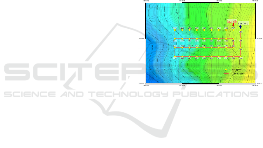
2.1 Waypoint-Based Navigation
The navigation systems employed in the majority of
present-day AUVs for commercial, civilian, and
military applications predominantly depend on
predetermined nominal tracklines, which are
composed of waypoints defined within the earth-
fixed frame (Figure 1).
Figure 1: Waypoints and corresponding nominal tracklines
established for an AUV mission.
In Figure 1, each waypoint is labelled with a number
that corresponds to the assigned reference depth. That
is, during the mission as depicted in Figure 1, the
longitudinal motion of an AUV is controlled to track
the reference depths in a sequential manner. It is
noted here that, in the context of waypoint-based
navigation, when a vehicle approaches the vicinity of
the current target waypoint within a predefined
acceptable range, the target waypoint is updated to the
subsequent one (Medagoda and Gibbens, 2010).
Therefore, in our waypoint-based AUV navigation
implemented by depth control, no sooner has the
vehicle reached (n-1)-th waypoint, i.e., wp_
n-1
, then
the reference depth of (n)-th waypoint is activated,
deactivating that of current (n-1)-th waypoint
simultaneously (Figure 2a). This waypoint activation
rule is also extended to the longitudinal motion
control of other control outputs. In case of altitude
control, a reference altitude is assigned to a waypoint,
making an AUV engage in terrain-following flight
until it reaches that waypoint. In Figure 2b, a terrain-
Longitudinal Motion Control of Underactuated Cruising AUVs for Acoustic Bottom Survey
755

following flight of an AUV implemented on the basis
of the waypoint-based navigation is depicted.
Figure 2a: Waypoint-based AUV navigation implemented
by depth control.
Figure 2b: Waypoint-based AUV navigation implemented
by altitude control.
In Figure 2a, d
r_n
represents the reference depth
assigned to the (n)-th waypoint, while in Figure 2b, h
r
represents the reference altitude assigned to all
waypoints for the terrain-following flight of an AUV.
Altitude control operates by utilizing the altitude
error, which is defined as the disparity between a
vehicle's current altitude and the designated reference
altitude.
It is worth noting that by substituting the altitude
error with its corresponding depth error, a depth
controller can effectively facilitate altitude control as
well (McPhail et al., 2010; Kim and Ura, 2015). In
such cases, we see that within the along-track interval
spanning from the (n-1)-th to the (n)-th waypoint,
altitude control is executed through the use of the
depth error, as shown in (1).
e
d
= -e
h
= h - h
r
(1)
In (1), e
d
and e
h
respectively denote the depth error
and altitude error, while h denotes the current vehicle
altitude.
2.2 Underactuation and Pitch Motion
As previously mentioned, cruising AUVs inherently
exhibit underactuation. Owing to the emphasis on
highly efficient cruising performance, cruising AUVs
feature a slender body shape. Like turning and pull-
ups, cruising AUVs alter their course by changing
their orientation, effectively changing their direction
of movement through manoeuvrers. This appears in
the form of the coupling in vehicle motion, that is, the
surge-heave-pitch coupling in longitudinal dynamics,
and sway-roll-yaw coupling in lateral dynamics of the
vehicle motion. It is well known that within the
framework of the longitudinal dynamics of a cruising
AUV, heave-pitch coupling is particularly strong
(McRuer et al., 1973; Kim and Ura, 2010). Hence, as
depicted in Figure 2, whenever an underactuated
vehicle adjusts its vertical position, corresponding
changes in its pitch attitude invariably occur. Here
comes the importance of selecting longitudinal
motion control in acoustic bottom survey mission
using a cruising AUV. As previously stated, the pitch
motion directly influences the quality of the acoustic
bottom survey.
2.3 Disruption in Acoustic Bottom
Survey
As previously noted, contemporary AUV-based
acoustic bottom surveys extensively utilize advanced
bottom mapping sonars like MBES or IFS. Using a
wide acoustic fan-shaped pulse, a bottom mapping
sonar necessitates precise tracking of its angular
movement to ascertain the transmission and reception
angles for each individual beam. Hence, the absence
of the proper attitude compensation for the platform
carrying the sonar prevents accurate echo sounding
through a bottom mapping system. In contemporary
bottom mapping sonar systems, real-time attitude
data sourced from navigation devices like an Inertial
Navigation System (INS) or an Attitude Heading
Reference System (AHRS) are commonly employed
for this purpose. However, there exists a limitation on
the attitude that can be compensated for in echo
ICINCO 2023 - 20th International Conference on Informatics in Control, Automation and Robotics
756

sounding. Figure 3 shows a result of acoustic bottom
mapping obtained by a near-bottom survey using a
cruising AUV. For the bottom mapping, a MBES
system working at 400 kHz was used.
Figure 3: A result of acoustic bottom mapping with
highlighted excessive along-track pitch rates.
As seen in the figure, the resulting bottom bathymetry
exhibits pronounced undulations in the along-track
direction, which are scarcely representative of real-
world bathymetric features. In Figure 3, along-track
pitch rates exceeding ±4 deg., a magnitude too
substantial to be adequately compensated for by a
typical bottom mapping sonar (Teledyne Reason,
2012), are overlaid onto the bottom bathymetry map.
As seen in the figure, the pronounced undulations
exhibit a strong correlation with the highlighted
along-track points, showing the prominent impact of
excessive pitch rates on the bottom mapping.
3 HARDWARE SYSTEM AND
GNC ARCHITECTURE
3.1 Hardware System
While the AUV navigation strategy outlined in this
paper holds a general-purpose nature, its initial
implementation was conducted on the hardware
system of our cruising AUV, referred to as NMRI C-
AUV#04. As the latest model of our cruising AUVs,
NMRI C-AUV#04 was designed and developed by
National Maritime Research Institute (NMRI) of
Japan. With the aim of achieving a highly-efficient
near-bottom survey over challenging steep terrains,
the NMRI C-AUV#04 prioritized the core features
encompassing exceptional high-manoeuvrability and
high-speed capability. As a result, accompanied by an
adjustable pitch range of ±80 deg., the NMRI C-
AUV#04 attains the maximum velocity of 3.3 m/s.
Figure 4 depicts the overall layout of the NMRI C-
AUV#04. And in Table 1, principal dimensions and
main specifications of the vehicle are listed.
Figure 4: Overall layout of NMRI C-AUV#04.
Table 1: Principal dimensions and vehicle specifications of
NMRI C-AUV#04.
Principal dimensions
Length overall 3.9 m
Diameter 0.65 m
Main specifications
Mass 545 kg
Speed (designed / max.) 1.8 / 3.3 m/s
Depth rating 2000 m
Controllable pitch
±80 deg.
Endurance 19 hrs. @ 1.8 m/s
3.2 GNC Architecture
Within our vehicle system, it is worth noting that we
utilize a Guidance, Navigation, and Control (GNC)
architecture that rests upon a hierarchical control
structure encompassing two distinct control levels.
Namely, this encompasses high-level control for
guidance and navigation, alongside low-level control
dedicated solely to tracking, as illustrated in Figure 5.
Figure 5: GNC architecture composed of two-level
hierarchical control.
Longitudinal Motion Control of Underactuated Cruising AUVs for Acoustic Bottom Survey
757
Generally, in the longitudinal dynamics of a cruising
AUV, akin to aircraft, the primary outputs encompass
surge, heave, and pitch. On the lateral axis, the
counterparts consist of sway, roll, and yaw (McRuer
et al., 1973). Following the prevalent model of
bifurcated vehicle dynamics commonly applied in
flight control, our GNC system incorporates two
distinct feedback controls at the lower level: one for
depth (altitude) to manage longitudinal dynamics, and
the other for heading to govern lateral dynamics.
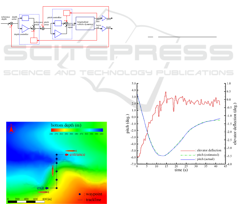
Figure 6 shows the schematic of the depth control
implemented in our vehicle system (Kim and Ura,
2009). As depicted in the figure, our depth control
consists of dual feedback loops. While the outer loop
governs depth control, it utilizes the depth error to
derive a proportional pitch reference, within which
the nested pitch-to-elevator control operates. Hence,
throughout our depth control process, the pitch
control operates implicitly and continuously.
Figure 6: Schematic of the depth (altitude) control
architecture of a cruising AUV.
4 SIMULATIONS
4.1 Conditions for Simulations
Figure 7 shows a 2D top view of the waypoints and
trackline superimposed onto the bathymetric map,
employed in our simulations.
Figure 7: Top view of the terrain, waypoints, and trackline
employed in simulations.
The digital bathymetric map data has been
sourced from the bottom bathymetry database
situated in Suruga Bay, located in Shizuoka
Prefecture, Japan. Running southward, the trackline
crosses the site's steepest terrain, where the maximum
along-track slope angle exceeds 40 degrees.
In this research, we have affirmed the suitability
of longitudinal motion control approaches for
acoustic bottom surveys by conducting simulations
utilizing the mathematical model of the GNC system,
in conjunction with the previously mentioned terrain
data, waypoints, and trackline. The GNC system
model comprises waypoint-based guidance, a low-
level motion controller implemented through
Proportional-Integral-Derivative (PID)
compensation, and the vehicle dynamic model, as
illustrated in Figure 6. Among these components, the
dynamic model of NMRI C-AUV#04 has been
derived through a system identification (SI) approach
(Kim et al., 2023). In the array of models used to
depict motion responses to actuator inputs, the pitch
to elevator deflection transfer function is shown in
(2).
0.0480.546s2.681ss
0.173s-q
23
e
+++
=
δ
(2)
In (2), q is the pitch rate of the vehicle in deg./s, while
δ
e
is the elevator deflection in degree. As depicted in
Figure 8, (2) accurately reproduces the vehicle's
actual pitch response, resulting in a normalized root-
mean-squared error (NRMSE) fitness of over 96%.
Figure 8: Estimated and actual pitch responses of NMRI C-
AUV#04.
The state-space pitch dynamics of NMRI C-AUV#4
actually used in our time-domain simulation is shown
in (3). Converted from the pitch to elevator deflection
transfer function (2), (3) is a canonical form, the state
r
d
e
δ
d
d
e
pd
K
id
K
dd
K
r
θ
θ
e
θ
p
K
θ
i
K
θ
d
K
q
w
θ
ICINCO 2023 - 20th International Conference on Informatics in Control, Automation and Robotics
758

variables in which are directly related to the pitch
response of the vehicle.
uBxAx
qqqq
+=
(3a)
uDxCy
qqqq
+=
(3b)
In (3), A
q
, B
q
, C
q
, D
q
are the state matrix, input matrix,
output matrix, and feedforward matrix of the pitch
dynamics of NMRI C-AUV#4 given by (4).
=
0.00.250.0
0.00.01.0
0.192-0.546-2.681-
q
A
(4a)
=
0.0
0.0
0.5
q
B
(4b)
In (3), x
q
∈ R
3
denotes the state vector. And as
inferred from (2), the output vector y
q
corresponds to
the pitch rate q, and the input vector u represents the
elevator deflection, denoted as
δ
e
. It is important to
mention here that in this paper, we consistently
employ degree units for angular displacement and
rate throughout.
4.2 Depth-Controlled Bottom Survey
Flight
At first, we performed a simulation in which NMRI
C-AUV#4 executes a depth-controlled bottom survey
flight by following the waypoints shown in Figure 7.
It is worth emphasizing that in this flight, the target
altitude is set to be 80 m, with a minimum allowable
altitude of 60 m. As a result, the along-track bottom
section, elevated by 80 m, serves as the target altitude
envelope. Figure 9 shows the 2D vehicle trajectory
resulting from the simulation. 3D view of the same
result is shown in Figure 10. As noted in the figures,
depth control lets the vehicle successfully follow the
waypoints.
Figure 9: 2D view of simulated depth-controlled bottom
survey flight.
Figure 10: 3D view of simulated depth-controlled bottom
survey flight.
Figure 11 depicts a comparison between the reference
pitch and the simulated pitch response throughout the
flight. The figure highlights excellent tracking
performance in pitch control, a crucial factor in
maintaining depth control performance. However, the
substantial pitch amplitude, nearly reaching 48
degrees, is anticipated to adversely affect the results
of the acoustic bottom mapping.
Figure 11: Pitch response during simulated depth-
controlled bottom survey flight.
Simulated pitch rates are also shown in Figure 12. As
seen in the figure, even the maximum peak value of
pitch rates is below 5 deg./s. Moreover, the majority
of pitch rates remain confined within the range of ±1
deg./s, a sufficiently small range to ensure stable
bottom mapping (Teledyne Reason, 2012). Therefore,
the pitch rate is thought to have limited adverse
impact on the acoustic bottom survey.
Longitudinal Motion Control of Underactuated Cruising AUVs for Acoustic Bottom Survey
759

Figure 12: Pitch rate during simulated depth-controlled
bottom survey flight.
In addition to the quality of acoustic bottom survey,
safety concerns also play a crucial role in the
evaluation of near-bottom flight for a cruising AUV.
As previously discussed, the inherent underactuation
of a cruising AUV poses a significantly greater risk
of bottom collision when compared to fully-actuated
underwater vehicles like hovering AUVs. Figure 13
depicts along-track vehicle altitudes that directly
relate to the safety concerns associated with potential
bottom collisions. As also noted in Figure 9, vehicle
altitudes are consistently confined within a narrow
range around the reference altitude of 80 m, ensuring
they remain safely above the minimum allowable
altitude of 60 m.
Figure 13: Vehicle altitude during simulated depth-
controlled bottom survey flight.
4.3 Terrain-Following Bottom Survey
Flight
Following the depth-controlled bottom survey flight,
we then have simulated terrain-following flight. With
the exception of the controlled output in longitudinal
motion control of the vehicle, all simulation
conditions remain identical to those employed in the
previously depicted depth-controlled bottom survey
flight. Figure 14 shows the 2D vehicle trajectory
derived from the simulation. 3D view of the same
result is depicted in Figure 15.
Figure 14: 2D view of simulated terrain-following bottom
survey flight.
Figure 15: 3D view of simulated terrain-following bottom
survey flight.
It is found that, overall, the flight trajectory exhibits a
closer resemblance to the reference altitude envelope
compared to that of the depth-controlled flight. And
it is worth noting that while we are currently using the
term reference altitude, we previously referred to it as
target altitude for the depth-controlled flight. In depth
control, the controlled output is the depth, not the
altitude, which is why we employed the term target
rather than reference.
ICINCO 2023 - 20th International Conference on Informatics in Control, Automation and Robotics
760

In Figure 14, it is evident that while the flight
trajectory closely resembles the reference altitude
envelope, there are more or less discrepancies in their
vertical positions. Moreover, in some tracks vertical
positions of the vehicle fall below the minimum
allowable altitude. This indicates significant safety
concerns arising from the increased risk of potential
collisions with the seafloor. A comparison between
the reference pitch and the simulated pitch response
throughout the flight is shown in Figure 16.
Figure 16: Pitch response during simulated terrain-
following bottom survey flight.
Apparently, the pitch response obtained from the
terrain-following flight is totally different from that
of the depth-controlled flight. As observed in the
figure, the reference pitch undergoes pronounced
fluctuations throughout the flight. This is not
particularly surprising, however, when considering
the schematic of our altitude control architecture. As
explained in 2.1 and 3.2, the pitch reference is derived
through the PID compensation of the depth error,
thus, for altitude control, the altitude error
counterpart. Hence, during terrain-following flights,
even minor alterations in the bottom elevation exert
an influence on the reference pitch. It is worth noting
here that in this simulation, the reference pitch is set
to be restricted within the range of ±40 deg., as seen
in Figure 16. Figure 17 shows simulated pitch rates.
Despite the presence of high-frequency fluctuations,
the magnitude of the pitch rate remains within a
sufficiently narrow range. As seen in the figure, the
majority of pitch rates are limited within the range of
±0.5 deg./s, which is half the range compared to that
of the depth-controlled flight. Thus, in bottom-
following flight, the pitch rate is unlikely to
detrimentally impact acoustic bottom mapping.
Figure 17: Pitch rate during simulated terrain-following
bottom survey flight.
Along-track vehicle altitudes are shown in Figure 18.
As previously mentioned and evident from Figures 14
and 18, in certain intervals, vertical positions of the
vehicle fall below the minimum allowable altitude.
Moreover, as observable in the figures, the majority
of vehicle altitudes are below 80 m, the reference
altitude for terrain-following flight. Thus, it can be
said that from a safety perspective, the terrain-
following flight result is not satisfactory.
Figure 18: Vehicle altitude during simulated terrain-
following bottom survey flight.
5 CONCLUSIONS
In order to clarify the impact of longitudinal motion
control approaches on acoustic bottom surveys, we
have conducted simulations of bottom survey flights.
Longitudinal Motion Control of Underactuated Cruising AUVs for Acoustic Bottom Survey
761

The simulation results indicate that the depth-
controlled bottom survey flight follows a trajectory at
moderate altitudes well within an acceptable range.
However, concerns arise regarding the potentially
harmful impact on acoustic bottom mapping due to
the pitch responses including some large amplitudes.
On the other hand, while the magnitude of the pitch
response is on a similar scale to that of depth control,
the magnitude of the pitch rate is notably reduced by
employing the terrain-following control approach.
However, safety issues may arise during a terrain-
following bottom survey flight. As a result of
unsatisfactory bottom-following flight, including
vertical vehicle positions below their allowable lower
limit, the risk of potential collisions with the seabed
can significantly increase. In conclusion, it is
essential to exercise caution when selecting a type of
longitudinal motion control. This decision should be
made after careful consideration of various factors,
such as the mission objectives, seafloor topography,
target or reference altitudes, and vehicle dynamics,
among others.
ACKNOWLEDGEMENTS
This work was supported by JSPS KAKENHI Grant
Number 21H01555.
REFERENCES
Honsho, C., Ura, T., Asada, A., Kim, K., Nagahashi, K.
(2015). High-resolution acoustic mapping to understand
the ore deposit in the Bayonnaise knoll caldera, Izu-
Ogasawara arc. Journal of Geophysical Research: Solid
Earth, 120(4), 2169–9313.
Honsho, C., Ura, T., Kim, K., Asada, A. (2016). Postcaldera
volcanism and hydrothermal activity revealed by
autonomous underwater vehicle surveys in Myojin Knoll
caldera, Izu-Ogasawara arc. Journal of Geophysical
Research: Solid Earth, 121(6), 4085–4102.
Ferrini, V. L., Fornari D. J., Shank, T. M., Kinsey, J. C.,
Tivey M. A., Soule, S. A., Carbotte, S. M., Whitcomb, L.
L., Yoerger, D., Howland J. (2007). Submeter bathy-
metric mapping of volcanic and hydrothermal features on
the East Pacific Rise crest at 9°50'N. Geochemistry,
Geophysics, Geosystems, 8(1), 1–33.
Kim, K., Sato, T., Oono, A. (2023). Depth-based pseudo-
terrain-following navigation for cruising AUVs. Control
Engineering Practice, 131(2023), article 105379,
10.1016/j.conengprac.2022.105379.
Cobra, D. T., Oppenheim, A. V., Jaffe, J. S. (1992).
Geometric distortions in side-scan sonar images: a
procedure for their estimation and correction. IEEE
Journal of Oceanic Engineering, 17(3), 252–268.
Lea, R. K., Allen R., Merry S. L. (1999). A comparative study
of control techniques for an underwater flight vehicle.
Int. J. of System Science, 30(9), 947–964.
Houts, S. E., Rock, S. M., McEwen R. (2012). Aggressive
terrain following for motion-constrained AUVs. In
IEEE/OES Autonomous Underwater Vehicles (AUVs).
1–7, Southampton.
Spong, M. W. (1998). Underactuated mechanical systems. In
Siciliano B., Valavanis K. P. (Eds.) Control Problems in
Robotics and Automation. Lecture Notes in Control and
Information Sciences, 230, 135–150.
Tedrake, R. (2009). Underactuated robotics: Learning,
planning, and control for efficient and agile machines:
Course Notes for MIT 6.832. Working Draft Edition.
Pedbody, M. (2008). Autonomous underwater vehicle
collision avoidance for under-ice exploration. Journal of
Engineering for the Maritime Environment, 222(2), 53–
66.
Caccia, M., Bruzzone, G., Veruggio, G. (2003). Bottom-
following for remotely operated underwater vehicles:
Algorithms and experiments. Autonomous Robots, 14,
17–32.
Hérissé B., Hamel T., Mahony R., Russoto, F.-X. (2010). A
terrain-following control approach for a VTOL
unmanned aerial vehicle using average optical flow.
Autonomous Robots, 29, 381–399.
McPhail, S., Furlong, M., Pedbody, M. (2010). Low-altitude
terrain following and collision avoidance in a flight-class
autonomous underwater vehicle. Journal of Engineering
for the Maritime Environment, 224(4), 279–292.
Bennet, A. A., Leonard, J. J., Bellingham, J. G. (1995).
Bottom following for survey-class autonomous
underwater vehicles. 9th International Symposium on
Unmanned Untethered Submersible Technology, 327–
336, Durham.
Caccia, M., Bruzzone, G., Veruggio, G. (1999). Active sonar-
based bottom-following for unmanned underwater
vehicles. Control Engineering Practice, 7, 252–268.
Medagoda, E. D. B., Gibbens, P. W. (2010). Synthetic-
waypoint guidance algorithm for following a desired
flight trajectory. Journal of Guidance, Control, and
Dynamics, 33(2), 601–606.
Kim, K., Ura, T. (2015). Longitudinal motion instability of a
cruising AUV flying over a steep terrain, IFAC-
PapersOnline, 48(2), 56–63.
McRuer, D., Ashkenas, I., Graham, D. (1973). Aircraft
Dynamics and Automatic Control, Princeton University
Press.
Kim, K., Ura, T. (2010). Applied model-based analysis and
synthesis for the dynamics, guidance, and control of an
autonomous undersea vehicle, Mathematical Problems
in Engineering, 2010, article ID 149385.
Teledyne Reason (2012). SeaBat 7125 AUV Operator's
Manual.
Kim, K., Ura, T. (2009). Optimal guidance for autonomous
underwater vehicle navigation within undersea areas of
current disturbances. Advanced Robotics, 23(5), 601–
628.
ICINCO 2023 - 20th International Conference on Informatics in Control, Automation and Robotics
762
