
Superposition and Decomposition Analysis of Limbs’ Vibration
Based on 6-UPS Tibia Fracture Reduction Surgical Robot
Zhenyi Wang, Hongjian Yu
*
,
Xiangyu Shen, Dongru Xie, Hao Wang and Zhijiang Du
State Key Laboratory of Robotics and Systems, Harbin Institute of Technology, Harbin, China
Keywords: 6-UPS Parallel Robot, Tibial Fracture Reduction Robot, Linear Vibration Units, Vibration Analysis,
Dynamics Analysis.
Abstract: This article establishes the inverse kinematic model and forward kinematic model of the 6-UPS Stewart
platform. Based on the existing 6-UPS tibial fracture reduction robot, the characteristics of the linear
vibration unit and its installation on the robot limbs are analyzed. Under the condition that the moving
platform outputs vibration along the force line direction, the superposition conditions of vibration in each
limb are verified through forward kinematics, and the basic conditions for vibration synthesis are solved.
Then, based on inverse kinematics, the desired vibration of the moving platform is decomposed to obtain
the vibration equations that need to be output by the linear vibration units on each limb. Finally, combined
with the Newton-Euler method, the robot dynamics are analyzed, and the model is imported into ADAMS
for simulation verification, providing a theoretical basis for realizing the rehabilitation function of the 6-
UPS tibial fracture reduction robot by adding linear vibration units.
1
INTRODUCTION
In recent years, the incidence of traumatic
orthopedic diseases has increased. The fracture
reduction surgery robot system can assist doctors in
better realizing the accurate planning and real-time
guidance of fracture reduction so that patients have
better reduction results. The existing fracture
reduction surgery robot mainly focuses on the
reduction function (Ye, 2012). Ralf Westphal et al.
from Germany developed a surgical reduction robot
system for long bone fractures (Westphal R -
Liodakis E). The robot adopts a typical industrial
robot structure to operate on the fractured part of the
patient. Terry K.K. Koo et al. proposed a computer-
assisted fracture reduction method in 2006, which
was powered by a unilateral external fixator to
reduce long bone fractures (Koo, 2006). Hu Lei's
team from Beihang University and the Chinese
People's Liberation Army General Hospital jointly
developed a fracture reduction robot system for the
lower extremity tibia (Li C, 2016). However, the
above studies do not consider postoperative
rehabilitation. Cai Chenxu's research on mechanical
vibration promoting bone cell growth shows that
low-amplitude high-frequency vibration, as a non-
invasive and safe treatment method, can effectively
shorten fracture healing time, promote fracture
healing, and have good effects on early-stage
fracture healing (Cai C, 2023). But there has been no
suitable solution for effectively combining fracture
reduction with functional rehabilitation.
This article presents the inverse kinematic model
and forward kinematic model for the 6-UPS Stewart
platform. It analyzes the characteristics of a linear
vibration unit and its installation on a 6-UPS tibial
fracture reduction robot. The article verifies the
superposition conditions of vibration in each limb
through forward kinematics when the moving
platform outputs vibration along the force line
direction. It solves the basic conditions for vibration
synthesis. Using inverse kinematics, the desired
vibration of the moving platform is decomposed to
determine the vibration equations that need to be
output by the linear vibration units on each limb.
The robot dynamics are then analyzed using the
Newton-Euler method and the model is simulated
and verified in ADAMS. The findings provide a
theoretical basis for incorporating linear vibration
units to achieve the rehabilitation function of the 6-
UPS tibial fracture reduction robot.
86
Wang, Z., Yu, H., Shen, X., Xie, D., Wang, H. and Du, Z.
Superposition and Decomposition Analysis of Limbs’ Vibration Based on 6-UPS Tibia Fracture Reduction Surgical Robot.
DOI: 10.5220/0012274600003807
Paper published under CC license (CC BY-NC-ND 4.0)
In Proceedings of the 2nd International Seminar on Artificial Intelligence, Networking and Information Technology (ANIT 2023), pages 86-92
ISBN: 978-989-758-677-4
Proceedings Copyright © 2024 by SCITEPRESS – Science and Technology Publications, Lda.

2
KINEMATIC ANALYSIS OF
THE STEWART PLATFORM
2.1 Inverse Kinematics of the Stewart
Platform
Simplifying the 6-UPS fracture reduction surgical
robot shown in Fig. 1, we obtain the robot
coordinate system depicted in Fig. 2, where the
hinge points on the moving and static platforms are
positioned on two planes. The hinge points of the
static platform are represented by 𝐵
𝑖1,2, ⋯,6
,
the hinge points of the moving platform are
represented by𝐴
𝑖1,2, ⋯,6
.
Then the coordinates of the hinge point on the
fixed platform in the fixed coordinate system can be
expressed as:
𝐵
𝑏
𝑏
0
𝑅
cos𝜑
R
sin𝜑
0
𝑖1
,
2
,
⋯
,
6
(1)
Then the coordinates of the hinge point on the
moving platform in the moving coordinate system
can be expressed as:
𝐴
𝑎
𝑎
0
𝑅
cos
𝜑
R
sin
𝜑
0
𝑖1
,
2
,
⋯
,
6
(2)
The pose of the moving platform relative to the
fixed platform is represented by a homogeneous
transformation matrix 𝑇:
(3)
Figure 1: Robot Integration Diagram.
The expression of hinge point coordinates in the
static coordinate system is as follows:
𝐴
𝑃𝑅⋅ 𝐴
(4)
Figure 2: Coordinate System of Stewart Platforms.
The rod length of each drive rod of a parallel robot
can be expressed as:
𝐿
𝑛
→
𝑃
𝑅⋅ 𝐴
−𝐵
(5)
In the equation:
𝑛
⃗
—— the direction vector of the drive rod𝐵
𝐴
;
𝐿
——The length of the drive rod
𝐵
𝐴
.
The inverse expression that can obtain the robot rod
length is:
𝑙
|
𝐴
𝐵
|
𝑃
𝑅⋅ 𝐴
−𝐵
(6)
The specific expression of the inverse rod length
can be obtained:
(7)
2.2 Positive Kinematics of the Stewart
Platform
To improve the operation speed of kinematics when
controlled by parallel robots, the solution of positive
kinematics is iteratively solved by Newton's method
(Liang, 2022).
For a given pose of a parallel robot 𝑞
𝑥
𝑦
𝑧
𝛼𝛽𝛾
, the inverse kinematics
equation can be converted to:
(8)
Combine the equations of the six rods to get a
system of equations:
𝐹𝑞
𝑓
𝑞
𝑓
𝑞
𝑓
𝑞
𝑓
𝑞
𝑓
𝑞
𝑓
𝑞
0
(9)
𝑇=
𝑐𝑜𝑠𝛽𝑐𝑜𝑠𝛾 𝑠𝑖𝑛𝛼𝑠𝑖𝑛𝛽𝑐𝑜𝑠𝛾−𝑐𝑜𝑠𝛼𝑠𝑖𝑛𝛾 𝑐𝑜𝑠𝛼𝑠𝑖𝑛𝛽𝑐𝑜𝑠𝛾+ 𝑠𝑖𝑛𝛼𝑠𝑖𝑛𝛾 𝑥
0
𝑐𝑜𝑠𝛽𝑠𝑖𝑛𝛾 𝑠𝑖𝑛𝛼𝑠𝑖𝑛𝛽𝑠𝑖𝑛𝛾+ 𝑐𝑜𝑠𝛼𝑐𝑜𝑠𝛾 𝑐𝑜𝑠𝛼𝑠𝑖𝑛𝛽𝑠𝑖𝑛𝛾−𝑠𝑖𝑛𝛼𝑐𝑜𝑠𝛾 𝑦
0
−𝑠𝑖𝑛𝛽 𝑠𝑖𝑛𝛼𝑐𝑜𝑠𝛽 𝑐𝑜𝑠𝛼𝑐𝑜𝑠𝛽 𝑧
0
00 01
𝑙
𝑖
=
(𝑎
𝑥𝑖
𝑟
11
+ 𝑎
𝑦𝑖
𝑟
12
+ 𝑥
𝑝
−𝑏
𝑥𝑖
)
2
+(𝑎
𝑥𝑖
𝑟
21
+ 𝑎
𝑦𝑖
𝑟
22
+ 𝑦
𝑝
−𝑏
𝑦𝑖
)
2
+(𝑎
𝑥𝑖
𝑟
31
+ 𝑎
𝑦𝑖
𝑟
32
+ 𝑧
𝑝
)
2
𝑓
𝑖
(𝑞)=(𝑎
𝑥𝑖
𝑟
11
+ 𝑎
𝑦𝑖
𝑟
12
+ 𝑥
𝑝
−𝑏
𝑥𝑖
)
2
+. . (𝑎
𝑥𝑖
𝑟
21
+ 𝑎
𝑦𝑖
𝑟
22
+ 𝑦
𝑝
−𝑏
𝑦𝑖
)
2
+(𝑎
𝑥𝑖
𝑟
31
+ 𝑎
𝑦
𝑖
𝑟
32
+ 𝑧
𝑝
)
2
−𝑙
𝑖
2
=0 (𝑖=1⋯6)
Superposition and Decomposition Analysis of Limbs’ Vibration Based on 6-UPS Tibia Fracture Reduction Surgical Robot
87

Newton’s method for solving a system of
nonlinear equations can be expressed as:
𝑞
= 𝑞
−𝐹
’
(𝑞
)
𝐹(𝑞
) (10)
where 𝐹
’
(𝑞) is the equation derivation of each
element, which can be expressed as:
𝐹
′
(𝑞)=
⎣
⎢
⎢
⎢
⎢
⎢
⎡
()
()
⋯
()
()
()
⋯
()
⋮⋮⋱⋮
()
()
⋯
()
⎦
⎥
⎥
⎥
⎥
⎥
⎤
(11)
After giving the member length of the six rods of the
parallel robot, given the initial pose 𝑞
of the
iteration, and specifying the iteration accuracy 𝜀 and
the maximum number of iterations 𝑁, the posture
that meets the requirements is obtained through
iterative operation.
3
DYNAMICS ANALYSIS OF
6-UPS STEWART PLATFORM
The linear vibration unit can directly convert
electrical energy into mechanical energy, driving the
spring-mass block for linear motion, and avoiding
radial vibrations. It provides delicate vibrations, fast
startup speed, controllable direction, and obvious
advantages. It is suitable for use as a vibration unit
in fracture rehabilitation. Its internal structure is
shown in
Fig. 3
. We can design a flange fixture as
shown in
Fig. 4
to install the linear vibration motors
in the limbs. As shown in
Fig. 5
, we have installed
the motors fixture designed in the limbs.
The general idea of using the Newton-Euler
method to establish the dynamic model of the 6-UPS
platform is: assuming that the motion acceleration
and angular acceleration of the required upper
platform are known, the vector relationship in the
fixed coordinate system is represented by the
rotation matrix and the coordinate transformation
matrix; Through the analysis of the kinematics and
dynamics of the outrigger, the Newton-Euler
dynamic equation of the outrigger is established, and
the force of each leg on the upper platform is
substituted into the Newton-Euler equation
established on the upper platform, and the closed-
loop dynamic equation of the entire platform is
simplified and finally obtained. Performing dynamic
analysis on a single rod as shown in Fig. 6.
Figure 3: Internal Structure of Linear Motor.
Figure 4: Linear Motor Connectors.
Figure 5: Linear Motor Physical Object.
Figure 6: Single Branch Limb Force Analysis.
Taking the first 𝑖leg as the research object, the force
analysis is shown in Figure 2, and the force balance
equation is as follows:
𝑚
𝑠
⋅𝑎
= 𝐹
+ 𝑚
𝑠
⋅𝑔−𝑓
,(𝑖=1,⋯,6) (12)
ANIT 2023 - The International Seminar on Artificial Intelligence, Networking and Information Technology
88

In the equation:𝐹
is the driving force of the limb
motor end; 𝑚
is the mass of the limb pusher; 𝑠
is
the direction vector of the limb; 𝑔 is the
gravitational acceleration; 𝑎
is the acceleration of
the pusher end of the limb; the force of the platform
on the limb is 𝑓
.
Taking the moving platform as the research
object, the dynamic equilibrium equation is:
𝑚
𝑎
= 𝑚
𝑔+ 𝐹
+
∑
𝑓
(13)
In the equation:𝑚
is the mass of the moving
platform; the center of mass acceleration of the
moving platform is; the external force acting on the
moving platform is 𝐹
. Substituting equation (12)
into equation (13), we obtain:
∑
𝐹
=
𝑚
𝛼
−𝑚
𝑔−𝐹
+
∑ (
𝑚
𝑠
⋅𝑎
−
𝑚
𝑠
⋅𝑔
)
(14)
Similar to force balancing, the moment balance
equation for the first limb is as follows:
(
𝑚
𝑟
+ 𝑚
𝑟
)
× 𝑔−𝐿
𝑠
× 𝑓
−𝑚
𝑟
⋅
𝑎
−𝜔
×
(
𝐼
+ 𝐼
)
−
(
𝐼
+ 𝐼
)
𝛼
−
𝜔
𝑚
𝑟
× 𝑎
=0 (15)
In the equation: 𝑚
is the mass at the motor end
of the limb; 𝐿
is the length of the limb motor end;
𝑟
and 𝑟
are position vectors from point 𝐵
to the
fixed part and the movable part of the motor,
respectively. 𝐼
and 𝐼
are the inertia matrices of
the fixed part and the movable part of the limb
around the point 𝐵
, respectively. 𝜔
and 𝛼
are the
angular velocity and angular acceleration of the
limb, respectively.
Taking the moving platform as the research
object, the moment balance equation of the moving
platform is listed:
𝐼
𝑎
+ 𝜔
×
(
𝐼
𝜔
)
−𝑀
−𝑟× 𝐹
=
∑
(
Rb
)
× 𝑓
(16)
In the equation: 𝑚
is the quality of the moving
platform; 𝐼
is the inertia matrix of the moving
platform; 𝑀
is the external moment acting on the
moving platform; 𝜔
, and 𝑎
are angular velocity
and angular acceleration of the moving platform; 𝑅
is the transformation matrix for the coordinate
system. Substituting equation (15) into equation
(16), we obtain:
∑
Rb
×
(
𝑚
𝑠
⋅𝑎
−𝑚
𝑠
⋅𝑔
)
+ 𝐼
𝑎
+
𝜔
× 𝐼
𝜔
−𝑀
−𝑟× 𝐹
=
∑
(
𝑅𝑏
)
× 𝐹
(17)
Combining the force balance equation (14) and
the moment equilibrium equation (17) gives a
dynamic equation of the following form:
𝐻⋅𝐹= 𝐾 (18)
In the equation :
(19)
(20)
4
SUPERPOSITION AND
DECOMPOSITION OF LIMB
VIBRATIONS
4.1 Superposition of Vibrations
After the completion of the fracture reduction
surgery, assuming the posture of the moving
platform is known, we can obtain the direction
vectors of the six branches. Based on the forward
kinematics model, assuming that the vibration
transmission time from the six branches to the
moving platform is the same, we multiply the
vibrations of the six branches by the decomposition
of the unit direction vectors of each branch. This
yields the vibrational components in the x, y, and z
directions. By representing these components in
three-dimensional space, we can observe the
following laws as shown in Fig. 7.
Figure 7a: Frequency is different, but amplitude and phase
are the same.
𝐾=
⎣
⎢
⎢
⎢
⎢
⎡
𝑚
𝑝
𝑎
𝑝
−𝑚
𝑝
𝑔−𝐹
𝐸
+
(
𝑚
𝑢
𝑠
𝑖
⋅𝑔−𝑚
𝑢
𝑠
𝑖
⋅𝑎
𝑢𝑖
)
6
𝑖=1
𝑅𝑏
𝑖
×
(
𝑚
𝑢
𝑠
𝑖
⋅𝑎
𝑢𝑖
−𝑚
𝑢
𝑠
𝑖
⋅𝑔
)
+ 𝐼
𝑝
𝑎
𝑝
+ 𝜔
𝑝
× 𝐼
𝑝
𝜔
𝑝
−𝑀
𝐸
−𝑟× 𝐹
𝐸
6
𝑖=1
⎦
⎥
⎥
⎥
⎥
⎤
𝐻=
𝑠
1
𝑠
2
𝑠
3
𝑠
4
𝑠
5
𝑠
6
𝑏× 𝑠
1
𝑏
2
× 𝑠
2
𝑏
𝑏
× 𝑠
3
𝑏
4
× 𝑠
4
𝑏
5
× 𝑠
5
𝑏
𝑏
× 𝑠
6
Superposition and Decomposition Analysis of Limbs’ Vibration Based on 6-UPS Tibia Fracture Reduction Surgical Robot
89
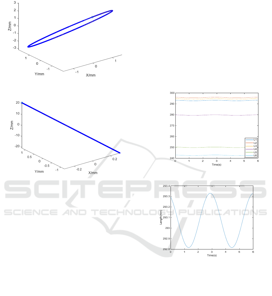
Figure 7b: Phase is different but amplitude and frequency
are the same.
Figure 7c: Amplitude is different, but phase and frequency
are the same.
It can be seen from the analysis that if you want the
robot moving platform to vibrate in the direction of
the force line, it is necessary to control the vibration
phase and frequency of each limb consistently and
adjust the direction of vibration by changing the
amplitude. Calculating the amplitude of each limb
needs to use the previously derived inverse
kinematics formula.
4.2 Decomposition of Vibrations
Vibration decomposition assumes that the moving
platform vibrates along the direction of the force line
after fracture reduction. It decomposes the desired
linear vibration of the moving platform. One
approach is to move the moving platform a small
distance along the force line direction and then study
the coordinate changes of each branch, calculate the
distance between the hinge points of the moving
platform and the fixed platform, and observe the
changes in the length of the branches. Another
approach is to add the displacement of the moving
platform to the initial pose of the robot, substitute
the new pose into the previously calculated inverse
kinematics model, and calculate the difference
between the branches before and after to obtain the
change in rod length. The results obtained by these
two methods are consistent.
Pair pose X=2; Y=2; Z=2; ROLL=pi/15;
PITCH=pi/12; YAW=pi/18. To facilitate the
observation of the magnitude of the amplitude, we
adjust the amplitude to 1μm, assume that the
dynamic platform vibrates along the force line, and
its vibration equation is 0.001sin(2t+2*pi/3). The
rod length change of each rod calculated by the two
methods is shown in Fig. 8, and the vibration of a
single axis can be found to be close to sinusoidal, as
shown in Fig. 9.
Figure 8: The length of the six limbs varies.
Figure 9: The length of a single limb varies.
5
DYNAMIC SIMULATION
BASED ON ADAMS
Simplify the model and import it into ADAMS. Set
the material properties and designate the push rod as
the driver. Substitute the vibration equations of each
supporting branch obtained in the previous chapter
into the drivers of each rod. Conduct simulations and
measure the force status of each rod component to
obtain Fig. 10. Compare the results of dynamic
numerical calculations with the results obtained
from ADAMS simulations, as shown in Fig. 11. It
can be observed that the numerical calculations and
Length(mm)
ANIT 2023 - The International Seminar on Artificial Intelligence, Networking and Information Technology
90

Figure 10: ADAMS simulation interface and results.
Figure 11: Comparison between ADAMS simulation and numerical calculation..
Figure 12: The vibration conditions of each component
after ma
g
nification.
simulations yield similar results. Perform separate
analysis and comparison of the dynamic calculation
results for each bar, and obtain Fig. 12 . The
calculation results indicate that within a margin of
error not exceeding 0.7%, it can be reasonably
assumed that the model is accurate.
6
CONCLUSION
This paper establishes the inverse kinematic model
Superposition and Decomposition Analysis of Limbs’ Vibration Based on 6-UPS Tibia Fracture Reduction Surgical Robot
91

and forward kinematic model of the 6-UPS Stewart
platform to solve the vibration repair function
required for tibial fracture reduction in the current 6-
UPS robot. Based on the existing 6-UPS tibial
fracture reduction robot, the installation of the linear
vibration device on the limbs is analyzed. Under the
condition of force-line direction vibration output by
the motion platform, the synthesis of the limbs'
vibration is achieved through forward kinematics,
and the vibration conditions of each limb are
verified under different vibration conditions. If the
motion platform of the robot needs to undergo linear
vibration along the force line, it is necessary to
control the phase and frequency consistency of each
limb vibration and adjust only the amplitude to
change the vibration direction. Then, based on the
inverse kinematics, the linear vibration set on the
motion platform is decomposed, and the vibration
equation of the linear vibration unit installed on each
limb is obtained. Finally, based on the Newton-Euler
method, the analysis of the 6-UPS tibial fracture
reduction robot is completed, and the model is
validated using ADAMS. The calculation results
show that within an error range of not exceeding
0.7%, the model can be reasonably considered
accurate. This paper provides a theoretical basis for
improving the rehabilitation function of tibial
fracture reduction robot through vibration.
ACKNOWLEDGMENTS
This work was financially supported by the Key-
Area Research and Development Program of
Guangdong Province (No.2020B0909020002) and
Self-Planned Task (No.SKLRS202211B) of State
Key Laboratory of Robotics and System (HIT).
REFERENCES
Ye R, Chen Y, Yau W. A simple and novel hybrid robotic
system for robot-assisted femur fracture reduction[J].
Advanced Robotics, 2012, 26(1-2): 83-104.
https://doi.org/10.1163/ 016918611x607383
Westphal R, Winkelbach S, Gösling T, et al. A surgical
telemanipulator for femur shaft fracture reduction[J].
The International Journal of Medical Robotics and
Computer Assisted Surgery, 2006, 2(3): 238-
250.https://doi.org/10.1002/rcs.81
Westphal R, Winkelbach S, Wahl F, et al. Robot-
assisted long bone fracture reduction[J]. The
International Journal of Robotics Research, 2009,
28(10): 1259-1278. https://doi.org/10.1177/
0278364909101189
Oszwald M, Westphal R, Bredow J, et al. Robot‐
assisted fracture reduction using three‐dimensional
intraoperative fracture visualization: An experimental
study on human cadaver femora[J]. Journal of
Orthopaedic Research, 2010, 28(9): 1240-
1244.https://doi.org/10.1002/ jor.21118
Liodakis E, Chu K, Westphal R, et al. Assessment of the
accuracy of infrared and electromagnetic navigation
using an industrial robot: Which factors are influencing
the accuracy of navigation? [J]. Journal of Orthopaedic
Research, 2011, 29(10): 1476-
1483.https://doi.org/10.1002/jor.21429
Koo T K K, Chao E Y S, Mak A F T. Development and
validation of a new approach for computer-aided long
bone fracture reduction using unilateral external
fixator[J]. Journal of Biomechanics, 2006, 39(11):
2104-2112.
https://doi.org/10.1016/j.jbiomech.2005.06.002
Li C, Wang T, Hu L, et al. A novel master–slave
teleoperation robot system for diaphyseal fracture
reduction: a preliminary study[J]. Computer Assisted
Surgery, 2016, 21(sup1): 162-167.
https://doi.org/10.1080/24699322.2016.1240304
Cai C, Zheng X, Shi M, et al. Bone collision detection
method for robot assisted fracture reduction based on
vibration excitation[J]. Computer Methods and
Programs in Biomedicine, 2023, 229:
107317.https://doi.org/10.1016/j.cmpb.2022.107317
Liang F, Tan S, Zhao X, et al. Kinematics and Dynamics
Simulation of a Stewart Platform[C]. Journal of
Physics: Conference Series, 2022, 2333(1):012026.
https://doi.org/10.1088/1742-6596/2333/1/012026
ANIT 2023 - The International Seminar on Artificial Intelligence, Networking and Information Technology
92
