
Design of UAV Cooperative Countermeasure Decision System
Yuhang Hui, Lei Li, Weixiu Yang, Xinguang Zhang and Ruiqi Sun
Beijing Institute of Space Long March Vehicle, China
Keywords: UAV Formation, Cooperative Confrontation, Task Allocation, Trajectory Planning.
Abstract: This paper designs a UAV Cooperative Countermeasure Decision System. The system focuses on the
effective integration of key technologies and algorithms such as multi-aircraft cooperative task assignment,
multi-aircraft cooperative track planning, and multi-aircraft cooperative formation control, and its
effectiveness is verified through digital simulation. This paper mainly establishes a multi-machine
cooperative task allocation algorithm based on satisfactory decision theory to achieve near-optimal task
allocation among multiple UAVs under various mission and resource constraints; a UAV path planning
algorithm based on a fast heuristic search strategy realizes fast and efficient UAV path planning and real-
time path re-planning in a dynamic environment; a multi-machine cooperative formation flight and
reconfiguration control algorithm based on induced routes is used to realize UAV formation flight formation
control; finally, the feasibility of the key technologies and algorithms of the system is verified through
visual simulation.
1
INTRODUCTION
With the rapid development of UAV technology,
multi-UAV cooperative combat has become one of
the important forms of combat in the future. In the
cooperative combat of multiple UAVs, it is very
important to effectively coordinate and control the
task execution and flight path planning of multiple
UAVs to improve operational efficiency.
In the past, UAV's task assignment and flight
path planning have been widely studied. In the field
of task allocation, experts and scholars have put
forward centralized task allocation mathematical
models such as multi-traveling salesman problem
(Secreat B R, 2001), vehicle routing problem
(O'Rourke K P, 2001), multi-choice knapsack
problem (Li Xiangmin, 2014), mixed integer linear
programming problem (An S, 2014), dynamic
network flow optimization model (Zhu D, 2013),
and distributed task allocation models such as multi-
agent decision theory and market mechanism
distributed Markov distribution constraints. In the
field of route planning, algorithms such as optimal
control method, roadmap method, grid method and
artificial potential field method are also proposed.
However, there are relatively few comprehensive
studies on cooperative task assignment, flight path
planning and formation control of multi-UAVs.
Therefore, in view of the cooperative confrontation
scenario of UAV formation, this paper designs a
UAV Cooperative Countermeasure Decision System
to support multi-UAV rative operations, and focuses
on the key technologies and algorithms such as multi
- UAV cooperative task assignment, multi - UAV
cooperative flight path planning and multi - UAV
cooperative formation control.
2
UAV COOPERATIVE
COUNTERMEASURE
DECISION SYSTEM
The UAV cooperative countermeasure decision
system aims to support multi-UAV cooperative
operations, to achieve effective coordination and
control among multiple UAVs, and to improve
operational efficiency and mission execution ability.
2.1 System Architecture
The UAV cooperative countermeasure decision
system mainly includes four modules, and each
module has the following functions
Task assignment module: responsible for
establishing the mathematical model of multi-
aircraft cooperative task assignment according to the
types and requirements of combat tasks, including
cost model and constraint model. Using the
algorithm based on satisfactory decision theory, the
Hui, Y., Li, L., Yang, W., Zhang, X. and Sun, R.
Design of UAV Cooperative Countermeasure Decision System.
DOI: 10.5220/0012274700003807
Paper published under CC license (CC BY-NC-ND 4.0)
In Proceedings of the 2nd International Seminar on Artificial Intelligence, Networking and Information Technology (ANIT 2023), pages 93-99
ISBN: 978-989-758-677-4
Proceedings Copyright © 2024 by SCITEPRESS – Science and Technology Publications, Lda.
93

approximate optimal task assignment of multiple
UAVs under different task and resource constraints
is realized.
Path planning module: Considering the high
dynamic and real-time requirements of UAV
cooperative operations, an UAV path planning
algorithm based on fast heuristic search strategy is
established, which can meet the constraints of threat
avoidance, platform performance, system resources
and mission requirements. The module can realize
fast and efficient path planning and real-time path
re-planning of UAV in dynamic environment.
Formation control module: aiming at improving
the cooperative penetration efficiency and task
execution efficiency of UAV, a multi-aircraft
cooperative formation flight and reconfiguration
control algorithm based on guidance routes is
established. According to the actual flight state and
the formation configuration error between UAVs,
different formation control strategies and methods
are adopted to realize rapid formation assembly,
synchronization and formation.
Simulation and verification module: this module
is used to verify the key technologies and algorithms
of the system. Collaborative countermeasure
strategy can be generated for different mission
scenarios and visual simulation can be realized.
Task allocation module
Path planning module
Formation control
module
Simulation verification
module
allocating task
Generating path
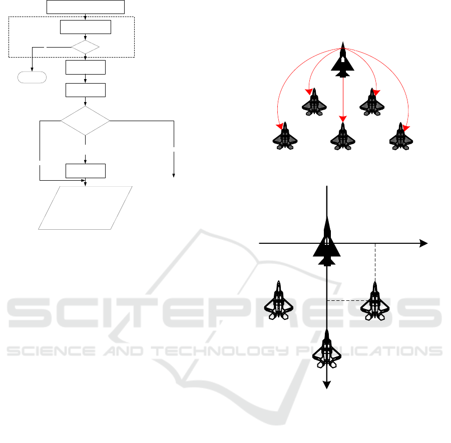
Figure 1: Framework of UAV countermeasure decision
system.
2.2 Multi-UAV Cooperative Task
Assignment
In this paper, a multi-machine cooperative target
assignment algorithm
(
Liao Mo, 2007
)
is adopted, and the
system framework of the algorithm is shown in the
figure, which consists of multi-machine target
assigners and individual UAVs. The part contained
in the oval virtual frame belongs to the management
decision-making part of UAV, which is generally
realized by UAV ground control unit.
The single-machine target manager receives the
attack target distributed by the multi-machine target
distributor, and sends this task target to the path
planner, who plans the path to execute the task; At
the same time, the single-machine target manager is
also responsible for providing a group of satisfactory
UAV individuals for the multi-machine target
distributor, and allocating parameters for each attack
target, such as path length, path threat, attack
efficiency, attack threat, etc. The calculation of these
parameters requires calling the path planner and
evaluation module.
Multi-UAV target distributor
Single UAV target
manager
Path
planner
Evaluati
on
module
UAV and control
navigation system
…………
…………UAV_2
UAV_N
goal set
Allocation
parameter
UAV_1
target
Path parame ter
Figure 2: Framework of Multi-machine Collaborative
Task Allocation System
.
The multi-machine target allocator sends the
target set and parameters to be allocated to each
single machine target manager, calculates the global
optimal allocation scheme according to the
satisfactory set and allocation parameters provided
by each single machine, determines the targets to be
attacked by each single machine, and then delegates
them to the single machine for execution.
The evaluation module of single machine gives
the parameters of UAV's destruction probability,
danger probability and so on. The path planner
calculates the flight path according to the mission
objectives and battlefield conditions of the single
aircraft, and gives the path length and threat cost.
The influence of various threats such as radar,
weapons, no-fly zone, electromagnetic zone and bad
weather zone on the battlefield is considered, and the
planned route, corresponding path length and threat
are given.
ANIT 2023 - The International Seminar on Artificial Intelligence, Networking and Information Technology
94

2.3 Multi-UAV Cooperative Path
Planning
Each plane corresponds to a path planner. The
coordination and control system of the flight
detachment is a large-scale system composed of
corresponding small aircraft systems, and the key to
its coordination is to determine the best time for the
detachment to reach the attack target. The solution to
this large-scale system is generally to adopt the
distributed control method of decomposition and
coordination, decompose the corresponding
problems in layers, let the planners of each aircraft
carry out relevant calculations, and use an aircraft
computer or assign a computer to undertake the
coordinated calculation task. The strategy of
decomposition is to select coordination variables and
determine coordination functions.
Take the coordinate variable ETA (Estimated
Time until Arrival), and record it as t
a
. The
coordination is the comprehensive cost of the team
(including fuel consumption and threat cost), with
the aim of minimizing coordination.
Suppose there are n planes attacking the same
target. For the No. i plane, there are.
Fuel cost:
𝐽
= 𝐶
𝐿
(1)
Threat cost:
𝐽
= 𝐶
+ 𝐶
𝐿
ℎ𝑖
𝑣
𝑖
(2)
Comprehensive cost:
𝐽
= 𝐽
+ 𝐽
𝑡𝑖
(3)
Where:
i
L is the flight path length,
hi
L is the
path length of the aircraft passing through the high
threat area, and
i
v is the aircraft speed.
fi
C
is the
weighting factor of fuel cost,
i
C is the weighting
factor of path cost in low threat area and
hi
C is the
weighting factor of path cost in high threat area.
The comprehensive cost of the team
J
is
𝐽=
∑
𝐽
=
∑
𝐶
𝐿
+ 𝐶
+ 𝐶
(4)
And satisfy the constraint conditions:
𝑣
,
≤𝑣
≤𝑣
,
𝐽
≤𝐹
𝐽
≤𝑇h
(5)
𝑡
≤𝑇
Where F
is the fuel limit, Th
is the acceptable
threshold of aircraft danger, and T
is the minimum
time limit for completing the attack mission.
Co or di nation mo dule
Coordination layer
Co or dinated co mpu ting modul e
Coordinated computing moduleInitial calculation module
Initial calculation module
Offline planning layer
Figure 3: Hierarchical structure of multi-UAV coordinated
path planning.
The hierarchical decomposition coordination
structure of flight path coordination planning
process is shown in Figure 3, which can be divided
into superior coordination layer and lower path
planning layer. Where 𝑆
,
is the destination arrival
time set of the num.𝑖 plane.
The next calculation of hierarchical planning can
be put into the path planner of each UCAV, and the
calculation can be divided into two modules: initial
calculation module and coordinated calculation
module.
The multi-machine coordinated path planning
algorithm comprises the following steps:
The initial calculation module carries out path
planning according to the fuel limit F
, the
acceptable threshold of danger Th
and the minimum
time T
to complete the attack task given by the
superior S
,
, and calculates the arrival time set of
the corresponding aircraft according to different
flight speeds to get the corresponding cost J
.
The coordination module of the coordination
layer determines the coordination variables
according to the arrival time set of each aircraft
participating in the assembly S
,
and the
corresponding cost J
, and according to the principle
of meeting the minimum total comprehensive cost
t
.
The coordination variables t
are sent to the
lower planning layer, and the coordination
calculation module in the planning layer plans the
flight route of the corresponding aircraft and
calculates the corresponding flight speed and
minimum comprehensive cost.
Design of UAV Cooperative Countermeasure Decision System
95
Have an
impact?
End
Module for receive co mmand s a nd chan
environment information
Check the influence of
changing environment on the
original route.
Path planning module
Speed re gulating
module
Relationship betwee n
arriva l ti me and limited
time
Planning results
Send it to the superior task
planner
And the lower pilot
Hover planning
module
The limited arrival time is too long.
Require accurate arrival
N
Meet the time requirement
Not enough time
Relevant information is sent to the
superior task planner.
(Path len gt h, crossing time an d distance,
minimum required time)
Figure 4: Coordinated path planner algorithm flow.
When it is necessary to re-coordinate the multi-
aircraft path planning due to environmental changes,
if the planned route of an aircraft cannot meet the
constraints, it should be chosen to give up
participating in the multi-aircraft assembly and
return to a designated waypoint instead.
If the minimum ETA of the 𝑁𝑜. 𝑖 plane is 𝑡
,
the ETA time of the team 𝑡
is:
𝑡
= 𝑚𝑎𝑥{𝑡
(
𝑖
)
(6)
2.4 Multi-Aircraft Cooperative
Formation Flight
This paper adopts a multi-UAV formation control
method based on induced route (
WU, 2016),
assuming that each UAV knows its expected
position in the formation before the formation task
begins. In the formation mode, the captain obtains
the expected route information and tracks the flight
of the route, and the wingman calculates his own
control instructions through the state of the captain
and the expected position information of the local
plane.
In the formation control algorithm based on
guidance route, the wingman's own control
command is a local guidance route, and the
wingman can track its expected position by tracking
this guidance route in real time. The expected
position of wingman in the formation can be
described by the lateral distance 𝐷
, forward
distance 𝐷
and height difference 𝐷
of the
relatively long aircraft, which is positive to the right
and backward, as shown in Figure 6.
长机
僚机僚机
lead aircraft
wing
plane
wing
plane
Figure 5: Coordinated path planner algorithm flow.
Figure 6: UAV expected position description.
According to the difference of position error
between the current position of wingman and its
expected position, different strategies are adopted to
generate the guidance route to realize the UAV
approaching its expected position quickly. When the
wingman is far away from its expected position, the
guidance route starts from the current position of the
wingman and ends at the expected position (as
shown in Figure 7.a), so that the wingman can fly to
the expected position quickly; When the wingman is
close to its expected position, the guidance route
passes through the expected position of the wingman
and is parallel to the current heading of the leader
(as shown in Figure 7.b), so as to guide the wingman
to approach the expected position smoothly. The
relay switching mode is adopted for the switching of
the two guidance routes, that is, the position error of
wi
D
w
D
f
i
D
f
D
ANIT 2023 - The International Seminar on Artificial Intelligence, Networking and Information Technology
96
the wingman when switching from the oriented
guidance route to the parallel guidance route is
smaller than that when switching from the parallel
guidance route to the oriented guidance route.
Leader
Wingman
wingman desired
position
(a) towards the guidance route
Leader
Wingman
wingman desired
position
(b) Parallel induced routes
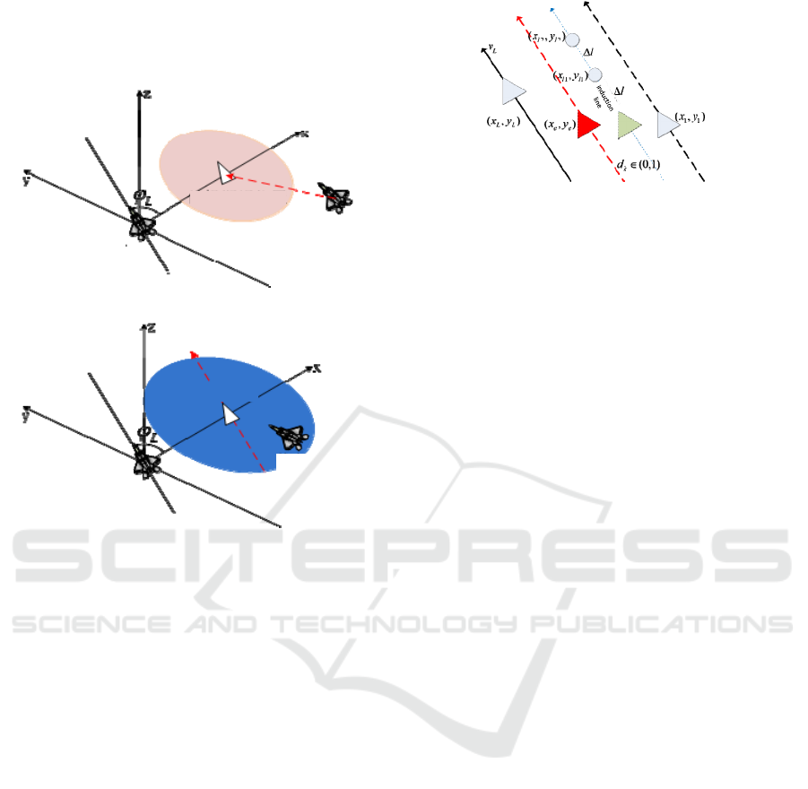
Figure 7: Guidance route generation strategy.
Suppose the current position of wingman is
(
𝑥
, 𝑦
, ℎ
)
, its speed and heading angle are (𝑣
, 𝜑
),
its expected position and speed are (𝑥
, 𝑦
, ℎ
, 𝑣
),
the current position of leader is (𝑥
, 𝑦
, ℎ
), and its
speed and heading angle are
(
𝑣
, 𝜑
)
. Then the
coordinates and speeds of two reference points on
the guidance route are calculated as follows
𝑥
= 𝑥
+ 𝑑
(𝑥
−𝑥
)+𝛥𝑙𝑐𝑜𝑠( 𝜑
)
𝑦
= 𝑦
+ 𝑑
(𝑦
−𝑦
)+𝛥𝑙𝑠𝑖𝑛( 𝜑
)
ℎ
= ℎ
𝑣
= 𝑣
(7)
𝑥
= 𝑥
+ 𝛥𝑙𝑐𝑜𝑠( 𝜑
)
𝑦
= 𝑦
+ 𝛥𝑙𝑠𝑖𝑛( 𝜑
)
ℎ
= ℎ
+ 𝑘
(ℎ
−ℎ
)
𝑣
= 𝑣
(8)
Where the fixed distance 𝛥𝑙 between two
reference points is long enough, and 𝑑
is a variable
with a value between 0 and 1, whose value
determines the position of the guidance route, and
the guidance route can be translated between the
current position and the expected position of the
wingman by changing the value of 𝑑
. During the
formation of the formation, the value of the 𝑑
is
Waypoint 2
wingman
desired
position
Wingman
induction
position
Wingman's
actual location
Leader
Figure 8: Generation principle of parallel induced route.
gradually increased from 0 to 1, guiding the
wingman to gradually approach its expected
position. The heading angle of UAV is defined as 0
in the east direction and positive in the
counterclockwise direction. The expected position of
wingman (𝑥
, 𝑦
, ℎ
) can be described by the
expected relative distance from the leader:
𝑥
= 𝑥
+ 𝐷
𝑠𝑖𝑛( 𝜑
) −𝐷
𝑐𝑜𝑠( 𝜑
)
𝑦
= 𝑦
−𝐷
𝑐𝑜𝑠( 𝜑
) −𝐷
𝑠𝑖𝑛( 𝜑
)
ℎ
= ℎ
+ 𝐷
(9)
The expected wingman speed 𝑣
is related to the
relative distance of the long wingman along the
induced route 𝑑
, the speed of the long wingman
and the speed difference of the long wingman.
{
𝑣
= 𝑘
𝑑
+ 𝑣
+ 𝑘
(𝑣
−𝑣
𝑐𝑜𝑠( 𝜑
−𝜑
))
(10)
The control method of wingman tracking
induced route is the same as that of long plane
tracking given route, which is realized by UAV
autopilot. The control of UAV is decoupled into
three aspects: longitudinal channel control, lateral
channel control and throttle lever position control.
Classical PID control is adopted, and the normal
overload command, roll angle speed command and
throttle increment command are obtained according
to the input route command, which are used as the
input of UAV model.
3
SIMULATION SCENARIO AND
VERIFICATION
3.1 Simulation Scenario
The blue UAV cooperates against the red target area,
and the target distribution in the red target area is
shown in Figure 9. Each assembly point can be
equipped with 16 UAVs, which are divided into two
categories: A is an electronic warfare UAV and B is
Design of UAV Cooperative Countermeasure Decision System
97

a strike UAV, including 12 UAVs in Class A and 4
UAVs in Class B.. Class A UAVs need to fly in
formation from the assembly point and perform
jamming tasks, while Class B UAVs need to strike
targets at fixed points. The schematic diagram is as
follows:
Flight path
target
Departure point
Figure 9: Schematic diagram of countermeasure scenario.
3.2 Simulation Results and
Implementation
As shown below, the main interface of the system is
mainly composed of five parts, namely, planning
state display module, indicating state display
module, simulation control module, two-
dimensional situation display module and three-
dimensional curve display module.
Planning status
display
indication
status display
Simulate Control
Button s
3D curve
display
Two-dimensional
situation display
Figure 10: Countermeasure scenario.
1) 32 UAVs interfere with and attack 4 targets
There are two kinds of battlefield threats in scenario
1, one is radar target and the other is enemy weapon
target, including 3 enemy radar targets and 1 enemy
weapon target. There are two UAV groups in Blue
(12 jamming UAVs and 4 attacking UAVs each),
which take off from different locations and gather in
designated airspace. After the collection is
completed, form a designated formation and fly in
formation. When the cluster reaches the target area,
the cluster is separated, and then the respective
cluster tasks are performed. In this scenario, there
are four targets and eight attacking drones, and the
task assignment of the targets to the drones is
completed by collaborative task assignment
algorithm to minimize the cost and maximize the
benefits.
Figure 11: Simulation result 1.
2) 32 UAVs interfere with and attack 7 targets
There are two kinds of battlefield threats in scenario
2, one is radar target and the other is enemy weapon
target, among which there are 6 enemy radar targets
and 1 enemy weapon target. There are two UAV
groups in Blue (12 jamming UAVs and 4 attacking
UAVs each), which take off from different locations
and gather in designated airspace. After the
collection is completed, form a designated formation
and fly in formation. When the cluster reaches the
target area, the cluster is separated, and then the
respective cluster tasks are performed. In this
scenario, there are 7 targets and 8 attacking drones,
and the task assignment of the targets to the drones
is completed by collaborative task assignment
algorithm to minimize the cost and maximize the
benefits.
Figure 12: Simulation result 2.
4
CONCLUSION
In this paper, a decision-making system of UAV
cooperative confrontation is designed, and the key
ANIT 2023 - The International Seminar on Artificial Intelligence, Networking and Information Technology
98

technologies and algorithms such as multi-UAV
cooperative task assignment, multi-UAV
cooperative flight path planning and multi-UAV
cooperative formation control are studied
emphatically. The simulation results show that the
system is effective and feasible in multi-UAV
cooperative operations. The system provides a useful
reference for cooperative countermeasure decision-
making of UAV formation, and provides important
support for improving operational efficiency and
mission execution ability.
REFERENCES
Secreat B R .Traveling Salesman Problem for Surveillance
Mission Using Particle Swarm Optimization[M].
BiblioScholar, 2001. ISBN-13: 9781288324309
O'Rourke K P , Carlton W B , Bailey T G ,et al.Dynamic
Routing of Unmanned Aerial Vehicles Using Reactive
Tabu Search[J]. Military Operations Research, 2001,
6(1):5-30.
Li Xiangmin, Yan Ji, Liu Bo, et al. A Survey of Multi-
Agents Cooperative Task Allocation Research [J].
Computer & Digital Engineering, 2014, 42 (12): 8.
https://doi.org/10.3969/j.issn1672-9722.2014.12.049
An S , Kim H J .Simultaneous task assignment and path
planning using mixed-integer linear programming and
potential field method[C]// International Conference
on Control. IEEE, 2014. https://doi.org/
10.1109/iccas.2013.6704241
Zhu D , Huang H , Yang S X .Dynamic Task Assignment
and Path Planning of Multi-AUV System Based on an
Improved Self-Organizing Map and Velocity
Synthesis Method in Thre e-Dimensional Underwater
Workspace[J]. IEEE Transactions on Cybernetics,
2013, 43(2): 504-514. https://doi.org/10.1109/
TSMCB.2012.2210212
Liao Mo, Chen Zongji. Multi-machine cooperative target
assignment algorithm based on satisfactory decision
[J]. Journal of Beijing University of Aeronautics and
Astronautics, 2007,33 (1): 5. https://doi.org/
10.3969/j.issn.1001-5965.2007.01.019
WU J C , ZHOU R , DONG Z N , et al . Formation flight
control method of multiple UAVs based onguidance
route[J]. Journal of Beijing University of Aeronautics
and Astronsutics, 2016, 42(7): 1518-1525. https://
doi.org/10.13700/j.bh.1001-5965.2015.0458
Design of UAV Cooperative Countermeasure Decision System
99
