
Lightweight Design and Analysis of Four-Wing UAV Fuselage
Structure Based on Topology Optimization
Guo Xiang, Yan Zhu
*
, Xingqun Cheng and Chang Liu
Liaocheng University, Shandong, China
Keywords: Four-Wing UAV, Fuselage Structure, Lightweight Design, Topological Optimization, Finite Element Analysis.
Abstract: The lightweight fuselage construction of unmanned aerial vehicles (UAVs), which are often utilized in the
military, agricultural, and other sectors, is a crucial element in enhancing their durability. First, the fuselage
structure of a small four-wing UAV for aerial photography is designed. Then, using the SolidWorks
program to create the 3D model of the fuselage structure and the Inspire software to do the variable density
topology optimization, the optimized model's mass is reduced by 51.5%. In the end, the static and dynamic
properties of the model before and after optimization are compared after being static and dynamically
analyzed using the ANSYS finite element analysis software. The results demonstrate that the optimized
model's strength and stiffness are within the permissible stress range and that it does not exhibit resonance
phenomena in a limited operating condition, proving the viability of optimization.
1
INTRODUCTION
Because of its advantages of low development cost,
reusable, safe, and reliable, UAV has seen increased
application in recent years in the military, aerospace,
agricultural (Li Bo - Dong Xulei), and other areas. A
composite UAV wing structure was created by
Zhang Qingsong and colleagues employing the
continuous topology optimization design approach
under the SIMP method (Zhang Qingsong, 2023).
The optimum volume is reduced by 35% and the
fatigue life of the sensitive area is examined using
the wing volume ratio as the limitation condition.
The analysis's findings demonstrate that the
improved wing structure satisfies the design
specifications. By utilizing the variable density
topology optimization approach and the OptiStruct
structure optimization platform, Liu Wenbin et al.
created the topology optimization model for the
outer cylinder pillar of the UAV landing gear. The
model's static properties were compared before and
after optimization, and it was shown that the
optimized model could cut weight by 20% while still
maintaining design specifications for strength (Liu
Wenbin, 2014).
By utilizing topology optimization technology,
predecessors have made some advancements in the
field of UAV lightweight and have provided a
reference scheme for use in this field; however, the
majority of research focuses on the structure of
UAV landing gear and wings, and there are few
studies on the optimization of the fuselage structure.
This study optimizes the fuselage structure of a tiny
four-wing UAV using the variable density topology
optimization method, offering yet another reference
approach for the development of lightweight UAVs.
2
FUSELAGE STRUCTURE
DESIGN
2.1 Integrated Layout
The four-wing UAV's general fuselage structure is a
cross-type arrangement, which is further separated
into "ten" layout and "X" configuration (Imang Eko
Saputro, 2019), as shown in Figure 1. The cross-over
"X" layout method was chosen because it has been
demonstrated to offer higher overall performance, a
more robust structure, and greater flexibility (Zhong
Jianwei, 2018).
The four-wing UAV's minimum wheelbase is a
crucial factor in determining its total size. Following
selection of the layout strategy, the wheelbase may
be established in accordance with the UAV's
intended use. The schematic layout of the UAV's
wheelbase design is shown in Figure 2, where L is
the frame's wheelbase, r
max
is the rotor's maximum
110
Xiang, G., Zhu, Y., Cheng, X. and Liu, C.
Lightweight Design and Analysis of Four-Wing UAV Fuselage Structure Based on Topology Optimization.
DOI: 10.5220/0012275600003807
Paper published under CC license (CC BY-NC-ND 4.0)
In Proceedings of the 2nd International Seminar on Artificial Intelligence, Networking and Information Technology (ANIT 2023), pages 110-116
ISBN: 978-989-758-677-4
Proceedings Copyright © 2024 by SCITEPRESS – Science and Technology Publications, Lda.
radius when the wheelbase is fixed, and r
p
is the
rotor's operational range. The four-wing UAV's
design primarily focuses on achieving airborne
shooting tasks; as a result, the weight requirement is
low and a two-blade paddle rotor with a 200mm
operating range is used.
max
22Lr=×
(1)
max
1.05
p
rr≥
(2)
According to formula 1 and 2, the wheelbase is
finally determined to be 600mm.
Combined with the working requirements and
lightweight criteria of the four-wing UAV, ABS is
selected as the material, and its material parameters
are shown in Table 1.
Figure 1: Placement scheme.
Figure 2: Design philosophy.
Table 1: ABS Material parameter.
Modulus of
elasticity
Poisson
ratio
Density
Yield
strength
2000MPa 0.35 1060kg/m3 45MPa
According to the above parameters, the three-
dimensional model was finally established by using
SolidWorks 3D modeling software, as shown in
Figure 3.
Figure 3: Fuselage 3D model.
Lightweight Design and Analysis of Four-Wing UAV Fuselage Structure Based on Topology Optimization
111

Figure 4: Vertical motion force.
2.2 Status Analysis
Four-wing UAVs often fly in a condition that
involves vertical motion, pitch motion, roll motion,
and yaw motion (Song Siqin, 2021). The focus of
this research is vertical motion since it places the
UAV in the most force on the fuselage. One
diagonal rotor rotates clockwise and the second
diagonal rotor revolves counterclockwise as the
UAV flies upward. The UAV rises when the lift
force produced by the whole rotor is higher than the
weight of the aircraft. The UAV drops when the lift
force produced is less than the weight of the aircraft.
The drone hovers in the air when lift equals weight
of the aircraft. It is not difficult to draw the
conclusion that the spiral wing end perpendicular to
the boom and the force of the UAV's own load are
the principal forces acting on the fuselage of the
four-winged UAV. The drone weighs 1.4 kg by
itself and 2.5 kg when loaded. Figure 4 depicts the
force situation, where F is the lift force, G is its own
gravitational pull, and f is the load. Since 4F=G+f is
an obvious conclusion, it follows that M
1
=0.975kg is
the weight that must be supported by a single
cantilever. The load force that a single cantilever
must resist during the vertical movement of the
UAV is 2M
1
according to the principle of 2 times
thrust weight ratio, hence the traction force that the
propeller must generate F
1
=2M
1
g=19.11N
(gravitational acceleration g=9.8m/s).
The final three-dimensional model was created
using SolidWorks 3D modeling software in
accordance with the aforementioned criteria, as
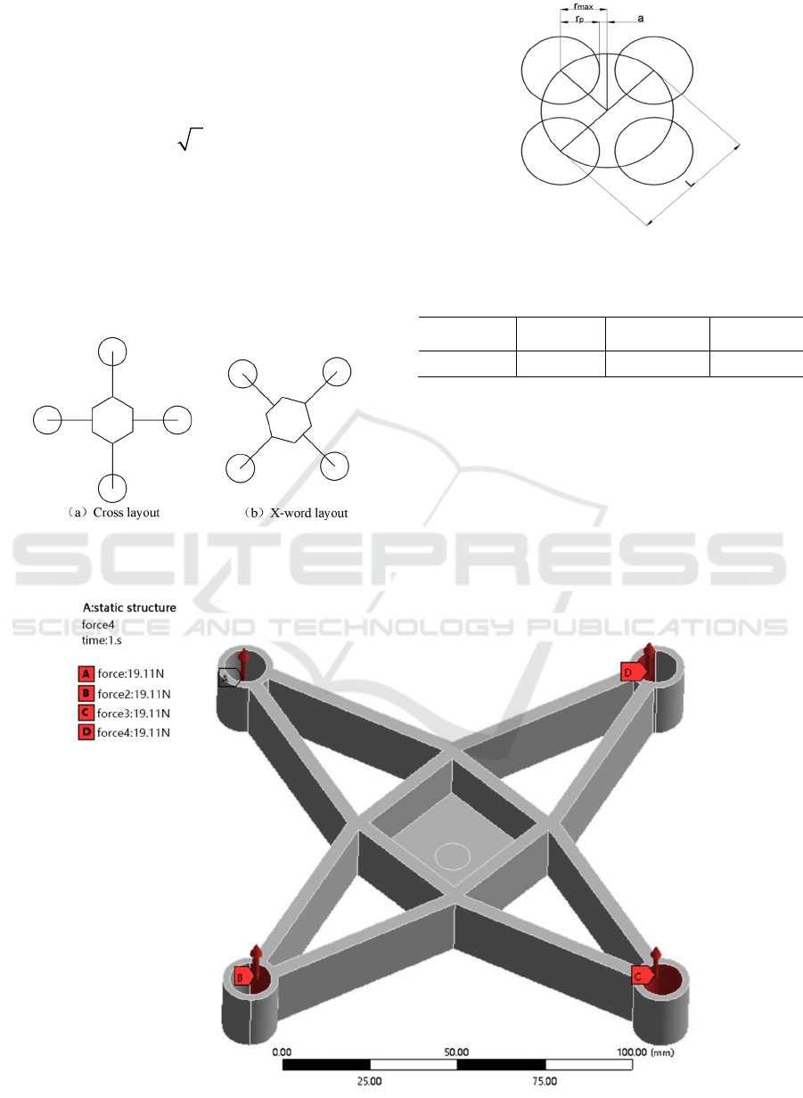
shown in Figure 3. In the ANSYS Static Structural
Module, the constraint, load, and grid division are
applied to the imported 3D model. The static
characteristic cloud map is then produced. A vertical
lift force of 19.11N was applied to the location
where brushless motors were mounted throughout
the fuselage, as illustrated in Figure 3, using the
whole fuselage as the study object. In order to assure
the accuracy of the results, inertial release is
introduced to replace the boundary condition since
every UAV structure is in a free state when in flight.
By using the patch adaptation approach, the 23,592
mesh units and 41,766 mesh nodes of the tetrahedral
mesh were identified. After analyzing the static
properties, the maximum deformation and
equivalent stress nephogram was produced, as
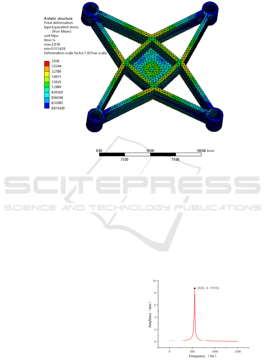
shown in Figure 5.
The highest deformation of the fuselage structure
occurs around the rotors, as shown in Figure 5(a),
and the maximum displacement under difficult
operating circumstances is 0.390mm. The four-
winged UAV's flight and control are little impacted
by this distortion. As noted in Figure 5 (b), the
maximum equivalent stress of the fuselage structure
is also present around the rotors and is 2.838 MPa,
which still leaves a significant gap when compared
to the ABS material's 45 MPa yield strength. As a
result, there is still room for weight drop and the
fuselage structure won't look to be failing from
fatigue.
(a) Maximum deformation cloud image
ANIT 2023 - The International Seminar on Artificial Intelligence, Networking and Information Technology
112
(b) Equivalent stress cloud image
Figure 5: Pre-optimization statics.
2.3 Fuselage Modal Analysis
Harmonious Response Analysis
During the actual flight, the four-wing UAV will
experience periodic vibration brought on by the
brushless motor of the power unit rotating (
Ren
Shuaiyang, 2021
), and this vibration has the most
influence on the four-wing UAV's flying process. In
order to minimize resonance between the excitation
source and the enhanced rotor folding mechanism,
which would result in the failure of the UAV
mechanical structure, the modal analysis of the
fuselage structure and the harmonious response
analysis may be used to understand its inherent
frequency characteristics. In this step, the dynamic
analysis of the fuselage model is performed using
ANSYS software to guarantee the logic and
dependability of the structural design.
The four-wing UAV's fuselage's chosen
brushless motor can run at a maximum speed of
5500 r/min, hence the highest frequency at which it
can operate without adversely impacting the
fuselage's condition is 92 Hz. Table 3 displays the
modal analysis of the UAV fuselage. The harmonic
response analysis of the fuselage is conducted to
produce the vertical motor direction displacement-
frequency curve at various frequencies, as shown in
Figure 6. This is predicated on the assumption that
the vibration of the fuselage caused by the brushless
motor changes in accordance with the simple
harmonic law. Combining the aforementioned study,
it is determined that the fuselage structure's first
order natural frequency is 200.09Hz, which is
significantly higher than the brushless motor's
working frequency and can successfully prevent the
development of resonance phenomena. Figure 6
shows that the four-wing UAV's displacement at its
maximum operating frequency is similarly
extremely modest, so it won't have an impact on the
UAV's flight.
Figure 6: Amplitude diagram.
Lightweight Design and Analysis of Four-Wing UAV Fuselage Structure Based on Topology Optimization
113

Figure 7: Topology optimization flow chart.
3
TOPOLOGY OPTIMIZATION
DESIGN BY VARIABLE
DENSITY METHOD
3.1 Topology Optimization Process
To increase the durability of four-wing UAVs,
topology optimization aims to provide a lighter
fuselage construction. Design engineers and
designers can use the Inspire program as an early
idea design tool (
Carlo Ferro, 2016
). The software
makes sure that technology supports the
development of designs that put a strong emphasis
on functionality and producibility. It makes it simple
and quick to develop and create conceptual product
prototypes that are architecturally flawless.
The program Inspire's Optistruct solver is
utilized in this work to optimize the fuselage model.
Figure 7 depicts the whole optimization procedure.
3.2 Optimized Result
The 3D model was imported into the Inspire
software with the four-wing UAV's fuselage
structure as the optimization object. A reasonable
optimization area was then designed in accordance
with the design requirements and experience,
removing as many redundant materials from the
model as possible to produce the desired effect. The
final optimized fuselage structural model is depicted
in Figure 8 with the objective of maximum rigidity.
Before optimization, the fuselage weighed
66.158 grams; after optimization, it weighed 34.08
grams. Topology optimization helped to lower the
weight by 51.5%, which increased the four-wing
UAV's endurance.
4
PERFORMANCE
VERIFICATION
4.1 Static Performance Comparison
The topologically optimized three-dimensional
model is imported into the ANSYS Static Structural
module for static analysis once again to see whether
the model's strength and stiffness criteria for the
four-wing UAV are met. Figure 9 displays the
deformation cloud picture and corresponding stress
cloud image.
Table 2 displays the static analysis outcomes for
the fuselage structure both before and after
optimization. The maximum deformation and stress
after optimization are 1.127mm and 11.793MPa,
respectively, and the rise is within the controlled
range, satisfying the design criteria of the four-wing
UAV statically.
Table 2: Comparison of results of static analysis.
Max
Deformation
/
mm
Maximum
Stress
/
MPa
Quality/g
Primitive 0.390 2.838 66.158
Optimize 1.127 11.793 32.078
Figure 8 Optimized model.
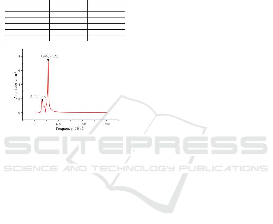
4.2 Dynamic Performance Comparison
The dynamic properties of the optimized model can
be determined through modal analysis of the
optimized fuselage structure and harmonious
response analysis. The analysis can then be used to
determine whether the altered size and shape
following topology optimization has an effect on the
strength and stiffness of the UAV during normal
operation. The harmonic response curve of the
improved model is shown in Figure 10. The
optimized fuselage will exhibit reasonably
noticeable vibration at 165Hz and 285Hz, as can be
shown in the picture, however these two frequencies
are far higher than the maximum operating
frequency of 92Hz.
ANIT 2023 - The International Seminar on Artificial Intelligence, Networking and Information Technology
114

(a) Maximum deformation cloud image
(b) Equivalent stress cloud image
Figure 9 Static analysis results of optimized fuselage mechanism.
The second frequency, which lowers by 45.86Hz
after optimization, has the largest change out of the
first six frequencies, as demonstrated in Table 3's
findings of the modal study performed before and
after the optimization of the fuselage structure. The
optimal frequency, which may successfully prevent
the occurrence of resonance phenomena, is
nevertheless much higher than the UAV's maximum
operating frequency of 92Hz. The study shown
above demonstrates that the UAV fuselage can also
Lightweight Design and Analysis of Four-Wing UAV Fuselage Structure Based on Topology Optimization
115
fully assure that the structural dynamic
characteristics after topology optimization fulfill the
design criteria, therefore this topology optimization
technique is applicable.
Table 3: Comparison of modal analysis results.
Frequency
/
Hz Primitive Optimize
firs
t
-stage 200.90 156.66
Second stage 202.59 156.73
Third stage 239.64 221.90
Fourth stage 489.72 469.32
Fifth stage 550.15 530.26
Sixth stage 646.43 630.73
Figure 10: Amplitude diagram.
5
CONCLUSION
1)Design and analysis are done on the fuselage of a
tiny, four-wing UAV that is primarily employed for
high-altitude shooting. The "X" layout concept is
used, and ABS is chosen as the material, taking into
account features like dependable construction, fluid
movement, and lightweight.
2)SolidWorks was used to model the fuselage
structure in three dimensions, and the Inspire
software's Optistruct structure optimization platform
was used to perform topological optimization on the
original fuselage mechanism. The weight of the
fuselage construction was ultimately decreased by
51.5% with the purpose of maximum rigidity, which
is significant for enhancing the UAV's endurance.
3)The static and dynamic properties of the
fuselage structure before and after topology
optimization were examined using ANSYS finite
element software. The static and dynamic properties
of the optimized model satisfied the design criteria
under the actual operating circumstances when the
static and dynamic parameters of the model were
compared between before and after optimization.
This optimization plan offers another theoretical
point of reference for structural lightweight design.
ACKNOWLEDGMENTS
This work was supported by the Natural Science
Foundation of Shandong Province (ZR2020ME113);
Innovation and Entrepreneurship Training Program
for College Students (CXCY2023122); Innovation
and Entrepreneurship Training Program for College
Students (CXCY2023155); Scientific Research Fund
of Liaocheng University (311102133311101910).
REFERENCES
Li Bo, Fang Kuncheng, Zhang Enyang, et al. Optimization
design and analysis of composite wing structure of a
certain electromagnetic-launch unmanned aerial
vehicle[J]. Composite Materials Science and
Engineering, 2015(12):5-11.
Xu Jingming, Shang Shuqi, Wang Dongwei, et al. Static
analysis and optimization design of heavy load
agricultural UAV[J]. Agricultural Mechanization
Research, 2023,45(10):16-23.
Dong Xulei, Zhu Ronggang, He Jianliang, et al. Military
application of UAV swarm based on blockchain[J].
Electronics Optics & Contral, 2023, 30(2):56-62+81.
Zhang Qingsong, Jia Shan, Chen Jin-bao, et al.
Configuration design and topology optimization of a
single wing for the hybrid unmanned aerial vehicle[J]. J
Tsinghua Univ (Sci & Technol), 2023,63(03):423-432.
Liu Wenbin, Zhang Ming, et al. Topology optimization of
an UAV landing gear structure[J]. Mechanical Science
and Technology for Aerospace Engineering, 2014,
33(11): 1753-1757.
Imang Eko Saputro, Alief Wikarta, Ali Muhtar. Topology
optimization on geometry of 3D printed “Impulse RC
Alien 4 Inch” racing quadcopter frame with polylactic
acid material. AIP Conference Proceedings 10
December 2019; 2187 (1): 050012. https://doi.org/
10.1063/1.5138342.
Zhong Jianwei, Zhong Xiaohua, Lu Minghui, et al.
Improved Design of Lightweight Structure of four-
rotor UAV [J]. China New Technology and New
Products, 2018(10):18-19.
Song Siqin, Wu Gang, Zhang Wenjing. Lightweight of
UAV based on the lattice structure characterized by
additive manufacturing[J]. Journal of Machine
Design, 2021,38 (06):25-29.
Ren Shuaiyang, Gao Aimin, Zhang Yong, et al. Finite
element analysis and topology optimization of folding
mechanism of six-rotor plant protection UAV[J].
Chinese Journal of Agricultural Mechanization,
2021,42 (09):53-58+194.
Carlo Ferro, Roberto Grassi, et al. Additive Manufacturing
Offers New Opportunities in UAV Research. Procedia
CIRP,2016,41:1004-1010. https://doi.org/10.1016/
j.procir.2015.12.104.
ANIT 2023 - The International Seminar on Artificial Intelligence, Networking and Information Technology
116
