
Kinematics Analysis of 4-RPUR Parallel Mechanism with 3D
Rotation Center Overlap for Ankle Rehabilitation
Xiangyu Shen, Hongjian Yu
*
and Zhenyi Wang
State Key Laboratory of Robotics and Systems, Harbin Institute of Technology, Harbin, China
Keywords: Less DOF Parallel Mechanism, Ankle Rehabilitation Robot, Kinematics Analysis.
Abstract: In many robot application environments, there are often requirements for the three-dimensional rotation
center of the robot operating platform to coincide, such as the design of the robot wrist, the design of the
robot to assist the human joint movement, etc. However, in the research and development of parallel robots
with few degrees of freedom, It is difficult to design a mechanism that can rotate the robot's moving
platform around a fixed point with limited degrees of freedom. The main content of this paper is the
kinematic analysis and discussion of a 4-RPUR parallel configuration that can realize three-dimensional
rotation around a certain point in space and the design of a reset rehabilitation robot based on this
configuration.
1
INTRODUCTION
The parallel mechanism with higher stiffness and
stronger bearing capacity is used for ankle joint
rehabilitation robots. With the development of
parallel mechanisms, the parallel configuration has
been applied more rapidly in rehabilitation robots. In
the late 20th century, Rutgers University in the
United States proposed the "Rutgers Ankle" for ankle
rehabilitation training. The system is based on the
Stewart configuration, which is the first application of
parallel mechanisms in medical rehabilitation
structures (Girone M, 2001). Later, Yooh and Ryu in
South Korea proposed a gas-powered ankle
rehabilitation system with four degrees of freedom,
which uses two parallel mechanisms to realize the
movement of the moving platform in three directions.
It can also achieve the relative rotation of the front
foot and the back foot of the affected foot (Kaufman
KR, 1996). Fan Xiaoqin et al from the North
University of China proposed a (2-SPS+PU)&R
hybrid ankle joint rehabilitation robot. Based on the
theory of traditional Chinese medicine treatment, this
configuration can realize a complete three-degree of
freedom rotation of the ankle joint and movement
along the tibia (Fan X, 2019). Then, Liu Chenglei et
al. (Liu C, 2021) proposed a parallel mechanism for
ankle joint rehabilitation. Based on the U
1
U
2
ankle
base fitting model, this scheme is a four-degree-of-
freedom generalized spherical mechanism, which
reduces the human-computer interaction force caused
by the ball-hinge motion model in the rehabilitation
process. At the same time, Han Yali et al. (Han Y L,
2015) proposed a 3-RUPS/S configuration of a 3-
DOF parallel robot. In addition, there are 3-RSS/S, 3-
PSS/S, and 4-SPS/S configurations with the same
principle, which are characterized by the central pillar
restraining excess mobility degrees of freedom (Liu G
Q, Zhao T S). Yu Runtian et al (Yu R T, 2015),
Zhang et al (Zhang X J, 2006), and Shiping Zuo et al
(Zuo S P, 2020) studied 3-DOF ankle joint
rehabilitation robots, but most of the robots developed
had poor reset function due to lack of freedom.
2
DESCRIPTION OF ROBOT
MECHANISM
2.1 Mechanism Modeling of 4-RPUR
The motion principle model of the ankle joint
rehabilitation robot proposed in this paper based on
the 4-RPUR configuration is shown in Figure 1. The
robot configuration has four limbs. This section
analyzes its configuration characteristics and
constraint characteristics. The four degrees of
freedom of the structure can meet the requirements of
rehabilitation and traction reset. At the same time, the
rotation center of the mechanism is in the center of
the mechanism, and the spatial position of the rotation
Shen, X., Yu, H. and Wang, Z.
Kinematics Analysis of 4-RPUR Parallel Mechanism with 3D Rotation Center Overlap for Ankle Rehabilitation.
DOI: 10.5220/0012275900003807
Paper published under CC license (CC BY-NC-ND 4.0)
In Proceedings of the 2nd International Seminar on Artificial Intelligence, Networking and Information Technology (ANIT 2023), pages 131-137
ISBN: 978-989-758-677-4
Proceedings Copyright © 2024 by SCITEPRESS – Science and Technology Publications, Lda.
131

center is related to the intersection points of the fourth
and fifth rotation auxiliary axes of each limb. It is
only necessary to design the adjusting mechanism to
change the relative position of the installation ring of
the fixed foot and the intersection point to meet the
different installation positions. Adaptation of rotation
centers for different foot sizes.
Figure 1: 4-RPUR parallel robot and hinge arrangement of
the moving and fixed platform.
In Figure 1, B
1
-B
4
points are the center positions of
the rotation axis connected by the fixed platform; P
1
-
P
4
points are rotating sub-center points connected
with the moving platform; The coordinates of the
rotation centers of the four Hooke hinges are denoted
as E
1
-E
4
, F
1
-F
4
, respectively. The platform is a square,
whose four vertices are B
1
, B
3
, B
3,
and B
4
; The
moving platform is a rectangle with four vertices P
1
,
P
2
, P
3
, and P
4
.
The coordinate system of the robot is established
as shown in Figure 1, in which the base coordinate
system O
1
-X
1
Y
1
Z
1
, the coordinate origin is at the
center point of the top platform (fixed platform), and
X
1
and B
1
B
3
are in the same direction. The coordinate
origin o1 of the moving coordinate system o
1
-x
1
y
1
z
1
is located at the junction point of the fourth and fifth
rotation axes of the limb calculated from the fixed
platform. The z
1
axis is completely perpendicular to
the robot's moving platform, and the positive
direction is toward the moving platform. We also
need to establish an additional reference coordinate
system O
2
-X
2
Y
2
Z
2
, whose origin coincides with the
moving coordinate system o
1
, its X
2
axis is parallel to
and in the same direction as the base coordinate
system X
1
axis, and its Z
2
is in the same direction as
the moving coordinate system z
1
.
According to the established coordinate system, it
is easy to obtain: From fixed platform to moving
platform, write the motion screw of the four limbs in
the reference coordinate system O
2
-X
2
Y
2
Z
2
:
)
(
45
5
45
12345
12 3
123
000
1010
000
$$$$ $ ,1,3
00
0000 0
00
ii
i
ii
ii i i i
ii i
iii
ll
m
nn
i
al a
cnc
==
(1)
()
5
45
45
12345
123
123
1010
000
000
$$ $$$ ,2,4
0000 0
00
00
i
ii
ii
ii i i i
iii
iii
l
mm
nn
i
bmb
cnc
==
(2)
2.2 Freedom Analysis
It can be seen that first, the six moving screws
included in the three-limb are linearly independent, so
the first three-limb reciprocal screw can be obtained
()
$ 010;000, 1,3
r
i
i==
(3)
This reciprocal screw restricts the motion of the
moving platform in the direction of the base
coordinate system Y
1
;
By the same token, we can also obtain the second,
four-limb reciprocal screw as:
()
$ 100;000, 2,4
r
i
i==
(4)
This reciprocal screw restricts the movement
of the moving platform in the direction of the
base coordinate system X
1
;
The constraint of the robot's four limbs on the
moving platform is the constraint force vector in the
X
1
O
1
Y
1
plane, which completely restricts the
movement of the robot's rotation center along the X
1
axis and Y
1
axis of the base coordinate system.
Therefore, this configuration loses the freedom of
movement in both directions, and the relative position
between the reference frame O
2
-X
2
Y
2
Z
2
synchronous
platforms is fixed, so it can also indicate that the
robot has a definite coincident three-dimensional
rotation center. The transformation of the constraint
force vector to the base coordinates has the two
largest linearly independent groups, so this
configuration has two virtual constraints. The degrees
of freedom of this configuration are calculated as
follows:
(5)
In the above equation, d is the order of the
mechanism, n is the Number of mechanism members,
g is the Number of motion pairs, f
i
is the Relative
freedom of the pair, and I is the number of virtual
constraints of the mechanism. The mechanism n=18,
g=20, f
i
=1 (i=1, 2, ... 20), according to the above
analysis of the dynamic platform has no common
1
(1)
i
i
g
M
dn g f I
=
=−−+ +
ANIT 2023 - The International Seminar on Artificial Intelligence, Networking and Information Technology
132

constraints, then λ=0. Mechanism d=6, but the virtual
constraint is 2, then I=2, so the degree of freedom of
the mechanism is M=60* (18-20-1) +20+2=4.
The basis of the four largest independent groups
of reciprocal screws is:
()
()
$ 010000
$ 100000
r
i
r
i
=
=
(6)
Because the moving platform can rotate around
three axes and move along the Z direction, rigid
motion pairs $
12
, $
22
, $
32
, and $
42
. Then each branch
will add another reciprocal screw. The reciprocal
screw fundamental solution system is obtained from
the reciprocal product being zero:
Constraint screw system of the four limbs:
()
()
()
1
45
5
31 4
4
2
13 5 4
$ 010000
,1,3
$10 ;1
r
ii
i
ii i
r
i
ii i i
ln
l
i
aa
n
l
cc m n
=
−
=
−
=−−
−
(7)
()
()
()
1
45
5
31 4
4
2
13 5 4
$ 100000
,2,4
$01 ; 1
r
ii
i
ii i
r
i
ii i i
mn
m
i
bb
n
m
cc l n
=
−
=
−
=− −
−
(8)
After rigidification, the resulting reciprocal screw
$
12
$
22
$
32
$
42
linear independent, the reciprocal screw
constraint of the moving platform is six linearly
independent screws with no additional degrees of
freedom. Therefore, the choice of input is reasonable.
3
ROBOT KINEMATICS
ANALYSIS
The pose of the moving coordinate system o
1
-x
1
y
1
z
1
is
relative to the base coordinate system O
1
-X
1
Y
1
Z
1
reflects the pose of the moving platform, namely, the
Angle sx around the X
1
axis, the Angle sy around the
Y1 axis, and the Angle sz around the Z1 axis, which
are represented by the Euler Angle. The moving
coordinate system o
1
-x
1
y
1
z
1
relative to the base
coordinate system O
1
-X
1
Y
1
Z
1
can be represented by a
transformation matrix:
[]
()() ()() ()()() ()() ()()()
()() ()() ()()() ()() ()()()
() ()() ()()
c sz c sy s sz c sx c sz s sy s sx s sz s sx c sz s sy c ss
s sz c sy c sz c sx s sz s sy s sx c sz s sx s sz s sy c sx
s sy c sy s sx c sy c sx
R
−+ +
=+−+
−
(9)
The coordinate vector of point P in the moving
coordinate system o
1
-x
1
y
1
z
1
is:
[][]
[][]
TT
''
12
TT
'
34
151.66 26.74 41.26 0 154 41.26
151.66 26.74 41.26 0 154 41 2
,
,.6
==
=− − = −
PP
PP
(10)
The coordinates of the P point converted from the
moving platform coordinates to the fixed platform
are:
[]
'
ii
PRPO=+
′
(11)
Among them 𝑂
′
00ℎ
; h is the distance
between the center of the moving platform coordinate
system and the center of the base platform coordinate
system. The coordinate vector of B in the fixed
coordinate system O
1
-X
1
Y
1
Z
1
is:
[][][ ][ ]
TT T
123 4
9500 0950 9500 0 9,, ,50
T
===−=−BB B B
(12)
Figure 2: Robot inverse solution.
Analyze in the plane shown in Fig 2:
Let the coordinates of E
1
in a fixed coordinate
system be:
[]
1
110
T
Ea b=
(13)
Doing the same for the other limbs can get the
equation as follow:
11 22 33 44
11 22 33 44
PE D PE D PE D PE D
EB R E B R EB R EB R
=== =
====
(14)
Where D is the base length of the defined
isosceles triangle, and R is the radius length of the
defined isosceles triangle. The values of a
1
, b
1
, a
2
, b
2
,
a
3
, b
3
, a
4
, b
4
can be determined by the equation and
the bar length constraints, and the coordinate vectors
of points E
1
, E
2
, E
3
, E
4
under O1-X
1
Y
1
Z
1
can be
determined.
For the first limb, so far, we can determine the
vectors E
1
o
1
, O
1
o
1
, and O
1
B
1
.
The modular bias distance e of the vector E
1
F
1
can
be obtained from the two-dimensional vector relation,
the vertical relation between E
1
F
1
and E
1
o
1
can be
obtained, and the coordinate vector of F
1
in the fixed
coordinate system O
1
-X
1
Y
1
Z
1
can be obtained.
Kinematics Analysis of 4-RPUR Parallel Mechanism with 3D Rotation Center Overlap for Ankle Rehabilitation
133

Through the vector operation in the plane, it can
be obtained that B
1
F
1
=B
1
O
1
+O
1
o
1
+o
1
E
1
+E
1
F
1
and
the change of B
1
F
1
can be obtained, that is, the
change of the moving pair of the first limb. In the
same way, we can find the change in the motion pairs
of the other three limbs.
The kinematics model of the robot is established
by ADAMS, and a series of movements are carried
out in the driving model under the initial state
(sx=0°,sy=0°,sz=0°,h=160mm). The kinematics of the
joint space in the ADAMS model is compared with
the calculation results of the inverse kinematics
derived in this paper, to verify the inverse kinematics
model of the robot.
(a)
(b)
(c)
(d)
Figure 3: Robot inverse kinematics verification. (a)(c)
ADAMS solution results under a certain spatial path (b)(d)
Solution results of inverse kinematics model in a space path
4
4-RPUR PARALLEL ROBOT
WORKSPACE
The coordinate search method based on inverse
kinematics is adopted in this paper. According to the
mechanism parameter design, it can be known that
the maximum elongation L
max
and the minimum
elongation L
min
, and the constraint condition of the
linear actuator length during the mechanical
movement is as follows:
min max
LLL≤≤
(15)
The point when the driving linear actuators of the
four limbs satisfy the linear actuator length constraint
at the same time is the point that the mechanism can
reach.
The specific search process is as follows: at the
determined position to be studied, arbitrary pose
parameters are given, and the length of the drive rod
is calculated through the inverse kinematics of the
robot in the previous chapter, to confirm whether it
can be reached, the desirable point is marked, and the
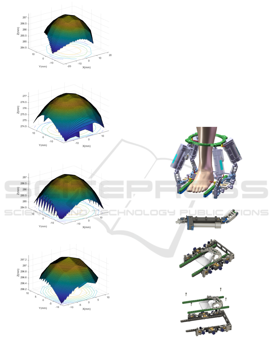
cycle is repeated in the previous step. The drawing
workspace is shown in Figure 4. The approximate
circular envelope surface of the working space of the
robot moving platform in the figure also indirectly
indicates that the robot has a coincident three-
dimensional rotation center.
ANIT 2023 - The International Seminar on Artificial Intelligence, Networking and Information Technology
134
(a)
(b)
(c)
(d)
Figure 4: Workspace of 4-RPUR. (a) Move 160 Mm along
the Z-Axis (B) Move 170 Mm along the Z-Axis (C) Move
180 Mm along the Z-Axis (D) Move 190 Mm along the Z-
Axis.
5
ROBOT STRUCTURE DESIGN
According to the configuration design above, the
robot's configuration is defined as 4-RPUR parallel
configuration. Based on the relevant human
dimension data, a parallel robot for medical-assisted
rehabilitation of ankle joints is designed as follows.
According to the structure and function of the robot,
the robot can be divided into three parts, which are a
fixed platform, a moving platform, and a limb part.
The static and static platforms are equipped with
mounting holes to fix the bone clips, the fixed
platform includes a rapid assembly and disassembly
structure of the robot, and the dynamic platform
includes an adjustment structure to adapt to different
sizes; The limb includes a drive rod and a hinge. The
specific structure is shown in Figure 5:
(a)
(b)
(c)
(d)
Kinematics Analysis of 4-RPUR Parallel Mechanism with 3D Rotation Center Overlap for Ankle Rehabilitation
135

(e)
Figure 5: Robot structure design. (a) Ankle rehabilitation
robot (b) Linear actuator (c-e) The moving platform of the
rehabilitation robot.
(a)
(b)
Figure 6: Robot adjusting structure. (a) The moving
platform regulates the structure along the finger bone (b)
The moving platform regulates the structure along the tibia.
The moving platform of the robot is mainly
composed of two parts, which we call the inner ring
and the outer ring. The inner ring is similar to the
moving platform. The outer ring has a heel
positioning device and an adjustment structure along
two directions, which can adapt the size of the ankle
bone, root bone, and talus of patients of different ages
and genders to ensure that it coincides with the center
of the ankle joint and reduces the passive slip of the
ankle joint during exercise, as shown in figure 5 (c-e)
and figure 6.
6
CONCLUSION
In this paper, a parallel mechanism 4-RPUR with a
spatially determined coincidence three-dimensional
rotation center is analyzed. The screw theory is
applied to model the mechanism, and the degree of
freedom of the robot is analyzed. At the same time,
the screw is used to check the selected active joint
and verify the correctness of the active joint selection.
The kinematics model of the 4-RPUR parallel robot
was deduced, the inverse kinematics analytical model
of the robot was obtained and verified, and the
working space was drawn. Finally, the structural
design of the robot was completed.
ACKNOWLEDGMENTS
This work was financially supported by the Key-Area
Research and Development Program of Guangdong
Province (No.2020B0909020002) and Self-Planned
Task (No.SKLRS202211B) of the State Key
Laboratory of Robotics and System (HIT).
REFERENCES
Girone M, Burdea G, Bouzit M, et al. A Stewart Platform-
Based System for Ankle Telerehabilit-ation[J].
Autonomous Robots, 2001,10(2):203-212. https://doi.
org/10.1023/A:1008938121020
Kaufman KR, Irby SE, Mathewson J, et al. Energy-efficient
knee-ankle foot orthosis: a case study[J]. Prosthetics and
Orthotics, 1996, 8(3): 79-85. https://doi.org/10.1097/
00008526-199600830-00003
Fan X, Li R, Li X, et al. (2-SPS+PU) &R Hybrid Ankle
Joint Rehabilitation Robot and Kinematic Performance
Analysis [J]. Mechanical Science and Technology for
Aerospace Engineering, 2019, 38(07): 1035-1040.
https://doi.org/10.13433/j.cnki.1003-8728.2019.20180277
Liu C, Zhang J J, Niu J Y, et al. Kinematic Performance of
4-DOF Generalized Spherical Parallel Mechanism for
Ankle Rehabilitation [J/OL]. Journal of Mechanical
Engineering, 2021, 57(21): 45-54.
https://doi.org/10.3901/JME.2021.21.045
Han Y L, Yu J M, Song A G, et al. Parallel robot
mechanism for ankle rehabilitation [J]. JOURNAL OF
SOUTHEAST UNIVERSITY (Natural Science Edition),
2015,45 (1): 45-50. https://doi.org/10.3969/j.issn.1001-
0505.2015.01.009
Liu G Q, Gao J L, Yang S X, et al. The configuration of the
ankle rehabilitation exercises parallel mechanism and its
kinematics analysis[J]. Development & Innovation of
Machinery & Electrical Products, 2005, 18(5): 13-15.
https://doi.org/10.3969/j.issn.1002-6673.2005.05.005
ANIT 2023 - The International Seminar on Artificial Intelligence, Networking and Information Technology
136

Zhao T S, Yu H B, Dai J S. An ankle rehabilitation device
based on a 3-RSS/S parallel mechanis-m[J]. Journal of
Yanshan University, 2005, 29(6): 471-475.
https://doi.org/10.3969/j.issn.1007-791X.2005.06.001
Yu R T, Fang Y F, Guo S. Design and performance analysis
of a rope-driven parallel rehabilitation mechanism of
ankle joint[J]. Robot, 2015, 37(1): 53-63.
https://doi.org/10.13973/j.cnki.robot.2015.0053
Zhang X J, Liu G Q, He C Y, et al. A General Statement on
the Ankle Rehabilitation Robot Based on Virtual Reality
[J]. Development & Innovation of machinery &
electrical products, 2006, 19(1): 29-31.
https://doi.org/10.3969/j.issn.1002-6673.2006.01.011
Zuo S P, Dong M J, Li J F, et al. Configuration design and
correction ability evaluation of a novel external fixator
for foot and ankle deformity treated by U osteotomy[J].
Medical & Biological Engineering & Computing, 2020,
58(3). https://doi.org/10.1007/s11517-019-02103-w
Kinematics Analysis of 4-RPUR Parallel Mechanism with 3D Rotation Center Overlap for Ankle Rehabilitation
137
