
Ground Resistance Measurement Method Based on
High-Frequency Pulses
Yuhe Zhang
1
and Hao Zhang
2
1
Chengdu University of Technology, Chengdu, China
2
Chengdu Onise Electronic Technology, Co., Ltd, Chengdu, China
Keywords: Measuring Device, High-Frequency Pulses, Impact Ground Impedance.
Abstract: In recent years, many substations have expanded accidents due to lightning strikes, most of which are
related to unqualified grounding resistance of the ground grid, so vigorously strengthening the regular
monitoring of the ground resistance of the ground grid has become an important task. At present, the
common use of high and low voltage and low frequency AC, high voltage low and high frequency AC, high
and low voltage variable frequency AC, high and low voltage DC, etc. flows through the measured body,
testing the ground resistance, impedance, the AC or DC used, the frequency is single, and the rising and
falling edges are slow, and the ground impedance is inductive impedance, capacitive impedance or pure
resistance impedance can not be well reflected. In order to solve the above problems, a grounding resistance
test method based on low-voltage high-frequency pulse voltage is proposed.
1
INTRODUCTION
1.1 Brief Introduction
The grounding device of the generator, substation
and transmission line is the fundamental guarantee
and important measure to maintain the safe and
reliable operation of the power system and ensure
the safety of electrical equipment and personnel
[
Jianwei Guo, 2008]. The grounding device not only
provides a common reference ground for various
electrical equipment, but also can quickly disperse
the fault current or lightning current in the event of a
fault or lightning strike, limit the rise of the ground
potential, and ensure the safety of people and
equipment [
Huadong Huang, 2013]. At present, many
power grounding systems are limited by technical
conditions, only pay attention to the measurement of
power frequency characteristics, but with the gradual
development of science and technology, the stability
of the power system has been greatly improved,
therefore, the main accidents at this stage are mainly
caused by impulse current and lightning current.
When the inrush current flows into the grounding
device of the generator and substation, if the
grounding resistance value of the ground grid is
large, it will cause the potential of the ground grid to
rise abnormally, causing the local potential
difference of the grounding system itself to exceed
the safe value [
Guanghui Song, 2016]. At this time, the
inductive component of the grounding grid cannot
be ignored, and the real state of the grounding grid
can not be well reflected by traditional measurement
methods.
In order to better reflect the real state of the
grounding grid, this paper proposes a high-frequency
pulse digital grounding resistance tester. Using
low-voltage high-frequency pulse voltage as the test
power supply, that is, 20KHz, square wave voltage
with a duty cycle of 50%, input to the ground point
under test, the square wave current of 20KHz flows
back to the tester through the far ground loop, by
testing the peak voltage of the three-point square
wave, the MCU calculates the grounding resistance
of the ground point under test, at the same time,
through the LCD display, the voltage waveform of
the measured point is displayed, and the grounding
resistance of the measured point is determined
whether it is capacitive, inductive or purely resistive
through the change of the rising edge and falling
edge of the square wave; And observe the changes of
the rising edge and falling edge of the square wave,
and roughly determine the size of the stray
inductance or stray capacitance.
Zhang, Y. and Zhang, H.
Ground Resistance Measurement Method Based on High-Frequency Pulses.
DOI: 10.5220/0012280300003807
Paper published under CC license (CC BY-NC-ND 4.0)
In Proceedings of the 2nd International Seminar on Artificial Intelligence, Networking and Information Technology (ANIT 2023), pages 253-256
ISBN: 978-989-758-677-4
Proceedings Copyright © 2024 by SCITEPRESS – Science and Technology Publications, Lda.
253
1.2 Current Situation at Home and
Abroad
At present, there are many ways to measure
grounding resistance, such as the three-pole method,
the four-pole method, and the frequency conversion
method, and in lightning detection, the most
commonly used method is the tripolar method
measurement. However, because there are many
influencing factors when measuring grounding
resistance, such as grounding wire resistance value,
grounding body own resistance, contact resistance
between grounding body and soil, etc., traditional
measurement methods can not well exclude the
influence of the above factors, so the following
measurement methods are proposed.
Power frequency high current method: the use of
injected larger current, so that it can measure the
depth deeper, but also the reverse method to
eliminate the power frequency interference, can
more accurately measure the resistance of the
ground resistance. However, it is precisely because
of the introduction of a large current that it means an
increase in cost and is difficult to achieve.
Heterogeneous frequency method: this method
uses alternating current, can well eliminate the
interference of power frequency current in the earth,
compared with the large current method, the
implementation degree of this method is greatly
improved, and the implementation cost is also
reduced, but because the current is small, the depth
of current penetration into the earth is also small.
Initially, voltammetry was used for ground
impedance measurement, and the experiment was
very primitive. In the fifties and sixties of the last
century, the former Soviet Union's E-type shaker
replaced the voltammetry, and the power supply was
a hand-cranked generator. In the 70s, the domestic
grounding impedance meter came out, and the ZC
series (such as ZC-28, ZC-29) was better than the
E-type shake meter in structure, measurement range,
index value, and accuracy. However, due to the
hand-cranked generator, the accuracy is not high. In
the 80s, the digital ground impedance meter was put
into use, and the stability was far higher than that of
the shake meter pointer type. The birth of clamp
resistance meters in the 90s of the last century broke
the traditional test method. In recent years, due to
the use of computer control technology, intelligent
ground impedance measuring instruments have been
produced, such as the Italian HT234. So far, there
have been high-current measurement methods such
as current and voltage method, interference
compensation method, frequency differential beat
method, difference frequency compensation method,
quadrupole method, as well as anti-interference
grounding shake meter, oscillator-frequency
selection voltmeter method, spectrum analysis
method, frequency conversion method and other
small current measurement methods.
In order to suppress the interference of
measurement, a method based on white noise was
proposed earlier, but it was not applied due to the
limitations of the measurement range and error. At
the end of the 90s of last century, a method based on
higher-order spectroscopy was proposed, and
research was carried out from the theoretical and
simulation aspects. In order to eliminate the error
and interference when measuring ground impedance,
in the 90s of last century, Chinese scientific and
technological personnel successively proposed the
double potential pole lead method, the additional
series resistance method, the potential pole lead
midpoint grounding method, the potential difference
method, and in recent years, the multi-pole method
was proposed. At the same time, foreign people have
also proposed the direct current method, numerical
calculation method, Berent compensation method,
and the Jopa-Laidi method in the operating state.
2
TEST METHODS
2.1 Working Principle
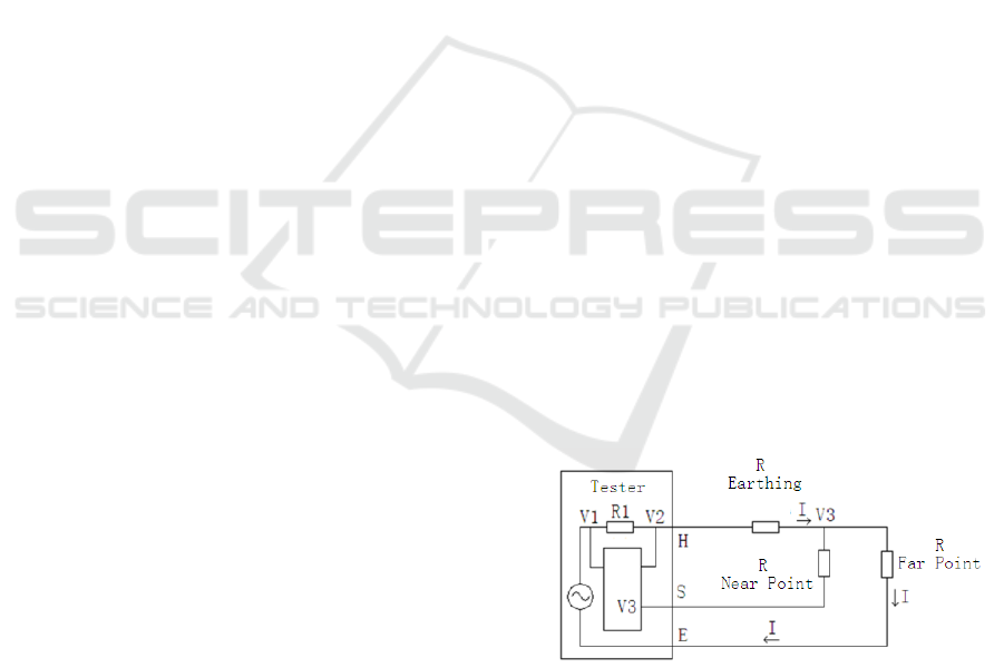
The grounding resistance test principle, as shown in
Figure 1, is the equivalent circuit for a
high-frequency pulse tester to test the grounding
resistance.
Figure 1: Tester Equivalent Circuit.
Among them, R1 is the current sampling
resistance inside the tester, and H outputs a
high-frequency square wave signal of 20KHz, which
flows back into the tester through R grounding and
R remote current loops.
ANIT 2023 - The International Seminar on Artificial Intelligence, Networking and Information Technology
254

Figure 2: Test Principle.
Through the trigger signal rising edge trigger,
delay 18uS, synchronously collect V1, V2, V3
voltage, and calculate the measured ground
resistance value as follows.as shown in Figure 2.
I=
𝑉1 −𝑉2
𝑅1
R=
𝑉2 −𝑉3
I
The delay is 18uS, synchronous acquisition, is
the flat section of the acquisition at the high level of
the square wave, which is equivalent to DC, so the
measured resistance is DC resistance. Observe the
V3 waveform, if the high level of the V3 waveform
does not have a flat section, or the flat section is too
short, it indicates that there is an inductance in the
grounding system, and the measured ground
resistance is not a pure resistance.
Through the change of the rising edge of the
waveform of V3, it is possible to know whether
there is an inductance in the grounding system, and
inductance is the most important parameter affecting
the shock response. When there is an inductance in
the grounding system, the rising edge of V3's
waveform slows down, as shown in Figures 3 and 4,
the larger the inductance, the slower the rising edge
of V3. Therefore, the response of the grounding
system to the impact is judged, because the lightning
signal, the harmonic component is many, and the
Figure 3: Grounding System Inductance 10uH.
frequency is high, and there is inductance on the
grounding system, which has the greatest impact.
Figure 4: Grounding System Inductance 1mH.
Shock response testing of grounding systems
requires a lightning current waveform with a steep
wave head and a large amplitude, as well as
extremely high voltages. Such devices are generally
bulky and bulky, making them impractical in field
testing. Through the rising edge change of the square
wave signal of the high-frequency pulse tester, to
observe whether there is inductance in the grounding
system under test, you can roughly understand the
impact response of the grounding system, without
quantitative testing.
2.2 Results and Simulations
For multi-point grounding systems, the test
grounding resistance can be unbroken by the
grounding wire. For example, transmission towers,
each tower must be grounded, and the top shielded
wire between the tower and the tower, that is, the
grounding wire, is equivalent to that each tower is
connected to the ground. When testing the grounding
resistance of a tower, existing testing techniques
require untying the grounding wire. Using a
high-frequency pulse grounding resistance tester,
you can do without untying the wires. as shown in
Figure 5. Transmission Tower Grounding Equivalent
Circuit.
Figure 5: Transmission Tower Grounding Equivalent
Circuit.
I0 is the current flowing through the ground
resistance of the tower under test, and I1 and I2 are
Ground Resistance Measurement Method Based on High-Frequency Pulses
255

the current flowing through the parallel tower.
Z=R+jX
It can be seen that the inductive reactance is
proportional to the frequency, and the capacitive
reactance is inversely proportional to the frequency;
Transmission line, taking model IJ-70 as an example,
the unit length resistance is: 4.6*10^(-4)Ω/m,
inductance is: L=1.27uH/m, capacitance is:
0.118uF/m.
The distance between the tower and the tower is
calculated in 500 meters, 50Hz power frequency
signal.
The inductive reactance is:
XL=2πfL=2*3.14*50*1.27*500*10^(-6)=0.2Ω;
The capacitive reactance is:
XC=1/2πFC=1/(2*3.14*50*0.118*500*10^(-6) )
=53.98Ω
20KHz square wave signal
The inductive reactance is:
XL=2πfL=2*3.14*20*10^3*1.27*500*10^(-6)=
79.8Ω
The capacitive reactance is:
XC=1/2πFC=1/(2*3.14*20*10^3*0.118*500*10
^(-6) )=0.13Ω
Due to the existence of the grounding wire
inductance, the impedance of the square wave signal
of the 20KHz test is large, the current flowing
through I1 and I2 is small, most of the current flows
through I0, and the grounding of the parallel pole
tower has little impact on the grounding resistance
test of the tower under test and can be ignored, so
the grounding wire can be solved when testing
multi-point grounding.
REFERENCES
Jianwei Guo. Research and fault diagnosis analysis of
grounding network of substation[D]. Shanghai Jiao
Tong University, 2008.
Huadong Huang, An Jun. Operation and maintenance of
electrical equipment and its grounding device[J].
Science and Technology Communication, 2013(19):2.
Guanghui Song. Research on unqualified analysis and
treatment of grounding resistance of substation ground
grid[J]. Architectural Engineering Technology and
Design, 2016(24).
Baba Y, Ishii M. Numerical electromagnetic field analysis
on measuring methods of tower surge impedance[J].
IEEE Transactions on Power Delivery, 1999, 14(2):
630-635
Ishii M, Baba Y. Numerical electromagnetic field analysis
of tower surge response[J]. IEEE Transactions on
Power Delivery, 1997, 12(1): 483-488
ANIT 2023 - The International Seminar on Artificial Intelligence, Networking and Information Technology
256
