Analysis of Finite Element Analysis of Steel Concrete Conversion
Beam Tip Node
Wenhua Liu
Fujian Chuanzheng Communications College, Fuzhou, China
Keywords: Type Steel Concrete Beam, Girder Tansfer, Finite Element Analysis.
Abstract: With the continuous expansion of my country's urban rail transit, the construction projects on the subway
have been widely used in recent years. The beam -type conversion structure is widely used in subway projects
due to its clear path transmission path, convenient construction, and low cost. The connection nodes of the
steel concrete conversion beam and wall of a project in this article are research objects. The ABAQUS
software analyzes the stress strain and deformation of the node. The results of the finite element analysis
indicate that the design of the type steel concrete conversion beam can meet the engineering needs. Some
suggestions on the measures for strengthening nodes are put forward, which can provide reference for similar
projects.
1 INTRODUCTION
In order to improve the utilization rate of urban land
and make full use of the subway vehicle section and
the upper space of the vehicle base, the converter
structure is usually used. The commonly used
conversion structures include beam -type conversion
and thick plate conversion. The beam -type
conversion is widely used in the subway projects due
to its clear path transmission path, convenient
construction, and low cost.
Based on a subway roof project, this paper uses
ABAQUS finite element analysis software to
calculate and analyze the connection joints of steel-
reinforced concrete transfer beams and frame-
supported wall columns. At the same time, according
to the stress-strain results calculated by ABAQUS,
some strengthening measures of transfer beams and
frame-supported wall columns are proposed.
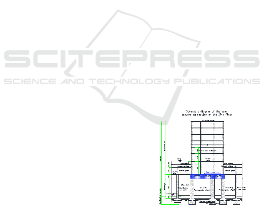
2 PROJECT OVERVIEW
Fuzhou a metro covered with a layer of garages layer,
the cover of the next layer of the subway out of line,
the throat area, the run-time library and the
maintenance of the library, garage-layer upper for
residential layer or business layer it. The project
according to the vertical using functions from the
lower to the upper divided into: under the cover of
Metro operational layer, cover with a garage layers,
the upper portion of the residential layer or business
layer, the cross-sectional view is shown in Figure 1.
The project is a multi-column frame supported
shear wall structure, the Metro cover a total of 39,
building high-rise residential and other centralized
commercial and matching floor, the cover with a total
construction area of about 45208.6 Square meter. The
basis of the use of 800~1000 millimeter diameter of
the concrete strength for the C35 perfusion pile.
Figure 1. The structure cross-sectional view.
In order to meet cover the following functional
requirements, while ensuring that the structure is safe,
suitable, economically, the conversion layer using a
Liu, W.
Analysis of Finite Element Analysis of Steel Concrete Conversion Beam Tip Node.
DOI: 10.5220/0012285500003807
Paper published under CC license (CC BY-NC-ND 4.0)
In Proceedings of the 2nd International Seminar on Artificial Intelligence, Networking and Information Technology (ANIT 2023), pages 437-441
ISBN: 978-989-758-677-4
Proceedings Copyright © 2024 by SCITEPRESS – Science and Technology Publications, Lda.
437

Girder tansfer solution. Girder tansfer structure of the
power transmission path is clear, the construction is
convenient, the cost is relatively low (Wang C Y.-
Cheng X H).
Connection cover and under the cover of the
converted beam is passed loads of important
structural member, and the“strong node of the weak
member”so that the node design is especially
important.
3 FINITE ELEMENT MODELING
3.1 Conversion Member Location
Select
Selected to take the structure in the most adverse
conditions typical steel transfer beams and frame
branch wall column of connected nodes for ABAQUS
analysis and calculation, the conversion of the beam
position as shown in Figure 2 shown. Steel beam
cross-sectional dimensions as shown in Figure 3 is
shown for 1200x2000(300x1500x32x32), the most
unfavorable conditions of the beam span is 11. 4m.
Figure 2. Conversion of the beam position of the figure.
Figure 3: Conversion of the beam size chart.
3.2 Element Types and Meshing
Concrete using eight-node linear hexahedral elements
and reduced integration, hourglass control the format
of the three-dimensional solid elements (C3D8R)
were simulated. The longitudinal reinforcement and
stirrups of the selection of the two-node linear three-
dimensional Truss element T3D2 simulation. Type of
steel using tetrahedral shell element S4R simulation.
In the meshing is required prior to first determine
to meet the accuracy of the mesh density, the use of
finite element software to provide the structured
meshing technique for the finite element model for
cell division.The grid is divided as Figure 4 shows.
Figure 4. Meshing diagram.
3.3 Material Constitutive Relationship
Conversion beams concrete used C40 strength, in-
the-wall concrete used C30 strength, the elastic stage
of the Poisson's ratio υ 0. 2, the density is taken
2400kg/m
3
. Steel pipe adopts Q345, reinforced the
use of HRB400. The steel used to meet the Mises
yield criterion of the elastic-plastic model, the
concrete using shaping injury model.
Concrete consists of two types of concrete
components, one is the stirrups constraints of the
concrete, and another for the stirrups outside
unconstrained concrete, two types of inconsistent,
which means that the stress-strain relationship of the
model used must be targeted. Stirrups constraints
concrete takes into account the distribution of the
Hoop characteristic value of the concrete stress-strain
relationship model, the model of the mathematical
formulas expressed as follows (Qian J R - Han L H).
11-87.01/
10223
y
2
2.0
32
xxxBx
xxAxAAx
(1)
The formula parameters are defined in detail in the
literature (Han L H, 2016).
3.4 Contact Interface Analog
Through the Embedded region (built-in area of the
longitudinal reinforcement and stirrups of the steel
skeleton embedded into the concrete below. Steel
beams with lap walls of the node selected binding Tie)
constraints.
Steel and concrete between the along the normal
to the direction of use is considered normal contact
300
Steel reinforced
concrete beam
ANIT 2023 - The International Seminar on Artificial Intelligence, Networking and Information Technology
438

stress in the steel tube and the concrete completely
passed the“hard”contact, and by the force of the
process, allowing the steel and concrete in contact
with each other after separation; along the tangential
direction using the Coulomb friction model.
3.5 Boundary Conditions
The wall base is applied to the solid end of the
constraint, limiting its six directions of the degrees of
freedom. The walls of the ring to the constraint, floor
lateral support as a safety Reserve will not be
considered.
3.6 Load
Load: material parameters, beam, floor permanent
loads and variable loads are by design take the value
1.3 D+1.5 L; the weight of the load by density and
acceleration of gravity finish is applied; a conversion
layer of the upper shear wall load by extracting YJK
big shock to calculate the bottom of the column force
data obtained, regardless of the adjustment factors.
4 CALCULATION RESULTS
AND ANALYSIS
4.1 Concrete Stress Analysis
Figure 5 visible wall in concrete the maximum
compressive stress is 64.46MPa, is greater than the
concrete tensile strength design value, in the corner
near the place; the maximum tensile stress of
2.10MPa, is greater than the concrete compressive
strength design value, in the beams of the wall node
position.Figure 6 visible beam in concrete the
maximum compressive stress is 14.61MPa, less than
the concrete compressive strength design value; the
maximum tensile stress of 2.0MPa, is greater than the
concrete tensile strength design value, in the beams of
the wall node position. Concrete plastic strain as
shown in Figure 7, the maximum plastic strain value
is 0.0246, located in the beam and the wall at the
junction of the neighborhood. The maximum plastic
strain value is very small, the material does not occur
destroyed.
Figure 5. Wall in concrete stress cloud diagram.
Figure 6. Beams in concrete stress cloud diagram.
Figure 7. Concrete equivalent plastic strain figure.
4.2 Reinforced with Steel Stress
Analysis
Analysis of reinforced and steel using the Mises yield
criterion, i.e., the Fourth of the yield strength of the
theory.Figure 8 shows the type of steel, the maximum
stress is 345MPa, and the stress is mainly
concentrated in the beam bottom tension and
and frame branch wall connecting the nodes
around.Figure 9 visible reinforced the maximum
stress of 360 MPa, the mid-span position of the beam
and bottom beam surface of the longitudinal
reinforcement of a larger force, and frame branch wall
connected to the node position of the beam reinforced
by the force is also larger.Overall, the block support
walls and conversion beam connecting node of stress
throughout the stage are more than their yield stress.
Greater
than f
c
Greater
than f
t
Analysis of Finite Element Analysis of Steel Concrete Conversion Beam Tip Node
439

Figure 8. Type steel Mises stress cloud diagram
Figure 9. Reinforced Mises stress cloud diagram.
4.3 Summary
In the most unfavorable load combination, the
conversion beams and frame branch wall of the
connection node of the concrete local damage, the
concrete portion enters the plastic State, but the
magnitude is small. Steel and rebar are not the yield,
the structure is subjected to slight damage, the overall
node in the rare case of an earthquake under the force
of good performance, meet the needs of large
earthquakes do not pour the principles.
5 NODE PROCESSING
MEASURES
5.1 Frame Branch Wall Column and
the Conversion of Beam-Column
Node Practices
Follow the “strong node of the weak member”of the
principle of frame branch wall column and the
conversion of beam-column node to take the
corresponding reinforcement measures, steel beam
inside the steel and rebar connection sample detailed
in Figure 10, the frame supported the wall of the
column and convert the beam node a large sample
detailed in Figure 11.
Figure 10. A large section of steel beam.
Figure 11. Large sample of frame support wallcolumn and
transfer beam joint
5.2 Conversion Member Construction
Technical Measures
Steel splice should be member of the welding surface
of the oil, rust removal. Bear welding work, welder,
according to the leading industry standard for the
steel structural welding code stipulates that
certificates.
Steel structure installation should be strictly
according to the drawings specified axis and the
position of the positioning, force and holes should be
correct; the lifting process should use the relevant
equipment strict calibration of vertical, and timely
positioning. Installation of the vertical degree, field of
lifting the error range should be consistent with the
national standards of the steel structure engineering
construction quality acceptance criteria of GB50205
the provision.
Steel plate hole, you should use the factory lathe
prepared hole, forbidden to live with oxygen cutting
openings.
Pegs before welding, should be a member of the
welding surface of the oil, rust removal, welding
inspection after the peg height of the allowable
deviation should be within±2mm, at the same time,
according to the relevant provisions of the sampling
check its quality of welding.
Steel reinforced concrete member within the steel
without coating processing.
screw
ANIT 2023 - The International Seminar on Artificial Intelligence, Networking and Information Technology
440

6 CONCLUSIONS
The present text to a subway on the cover of the
project as the basis for steel reinforced concrete
transfer beams of the wall node to the ABAQUS finite
element calculation and analysis. Results showed that
the conversion of the beam and frame branch wall in
a large earthquake case of a partial concrete into a
plastic State, but the number was smaller, rebar and
steel are not to exceed the respective yield
stress.Verify in the most adverse conditions and still
maintain good mechanical performance, can meet
large earthquake conditions performance
requirements. This article for conversion beams and
frame branch wall design calculation of ideas and the
node processing measures may be for the same
project reference.
REFERENCES
Wang C Y. The Research and Contrast on RC 、 SRC
Transfer Beam and the Combined Action With Upper
Short-Pier Shear Wall (D). Xi'an University of
Architecture and Technology, 2009.
Dong K, Sun Y. Discussion on the practical design method
of girder transfer floor for high-rise
building(J).Industrial Construction, 2009, 39:265-269.
Cheng X H, Ma F .Beam Frame Supported Shear Wall
Structure Based on the ANSYS Finite Element Static
Analysis of Beam-Type Transfer Floor (J).Advanced
Materials Research, 2013, 788: 508-510.
https://doi.org/10.4028/www.scientific.net/AMR.788.5
08.
Qian J R, Cheng L R, Zhou D L. Behavior of axially loaded
concrete columns confined with ordinary hoops (J).
Journal of Tsinghua University: Natural Science Edition,
2002, 42(10):5.
Han L H. Concrete-filled Steel Tube Structure-Theory and
Practice (3rd Edition) (M). Beijing: Science Press, 2016.
Analysis of Finite Element Analysis of Steel Concrete Conversion Beam Tip Node
441
