
Bidirectional DC-DC Converter For Electric Vehicle Application
Using FLC Controller
Taskeen M Challigid
1
a
, Manish Rathi
1
b
1
Department of Electrical & Electronics Engineering,PDA college of Engineering & Technology, Gulbarga, India
Keywords: Three level unidirectional MLI, AC_DC_AC conversion, Bidirectional Power flow capability, Reduced
components, T-type inverter.
Abstract: In this, A design of bidirectional DC-DC converter is proposed which is suitable for electric and hybrid
vehicles applications. The main advantages of the proposed structure are that it can utilize different energy
sources with different voltage-current characteristics. Moreover, the proposed structure is bidirectional, and
battery could be charged in braking mode too. These features along with high voltage gain make this converter
an excellent alternative for DC-DC converters in electric vehicles. A speed control structure is added to this
in order to control the speed of the motor using Fuzzy Logic Control (FLC) and the performance of the
proposed controller with conventional Proportional Integral (PI) controller under steady state and transient
conditions are compared in terms of peak overshoot, settling time, torque ripples, etc. the simulation is carried
out in MATLAB/Simulink software.
1 INTRODUCTION
Due to significant challenges including
contaminants in the air, global warming, and
increasing demand for fossil fuels, the electric vehicle
(EV) sector is expanding quickly nowadays. The
primary components of EVs are power converters and
drive systems, and several research initiatives are
carried out to increase the density and efficiency of
these converters. There are several different varieties
of EVs, including fuel cell-electric vehicles (FCEVs),
hybrid electric vehicles (HEVs), and pure electric
vehicles (PEVs). Each of these cars has an electric
motor that operates using batteries that are wired
through voltage source converters (VSCs) to the
motor. On the contrary, a large DC voltage is
necessary at the motor side with regard to the direct
link among the power supply of the electrical drive
and its voltage. As a result, a DC-DC converter
should be used to transform the weak voltage from
the battery side into a high voltage DC-link. Indeed,
the battery's output voltage drops as the level of
charge, or SOC, of the battery increases. The DC-DC
converters used in electric vehicles (EVs) should be
a
https://orcid.org/0009-0007-9645-6502
b
https://orcid.org/0009-0005-4809-3642
able to function in a bidirectional mode. The
converter can send power from the battery side to the
motor side and the other way around thanks to this
characteristic. As a result, the battery is able to be
charged while the vehicle is in braking mode. High
efficiency, compact size, little battery current ripples,
and light weight are some of the most crucial factors
that should be taken into account while designing
these converters. The two types of bidirectional DC-
DC converters are isolated and non-isolated
architectures. A lightweight, highly reliable 3kW
standalone DC-DC converter with bidirectional
operation is presented for electric cars (Ansari, P.
Cheng et al,2016). With this converter, there are fewer
switching components needed for power transfer in
both directions. Contrary to other isolated converters,
this converter is less efficient. For fuel cell cars, a
clamp separated, bidirectional DC-DC converter is
shown that does not employ a snubber circuit.
Zero switching is employed on the converter's
primary side and secondary side, respectively.
Regarding bipolar DC micro grids, a brand-new
reversible step-up DC/DC converter with high
voltage gain and bipolar DC outputs is described.
24
M Challigid, T. and Rathi, M.
Bidirectional DC-DC Converter For Electric Vehicle Application Using FLC Controller.
DOI: 10.5220/0012504700003808
Paper published under CC license (CC BY-NC-ND 4.0)
In Proceedings of the 1st International Conference on Intelligent and Sustainable Power and Energy Systems (ISPES 2023), pages 24-31
ISBN: 978-989-758-689-7
Proceedings Copyright © 2024 by SCITEPRESS – Science and Technology Publications, Lda.

However, the lack of an isolating transformer places
restrictions on this converter's voltage conversion
factor. A boost-powered converter with multiple
inputs and outputs that offers both gentle switching
and a high voltage gain is offered. This converter is a
good contender for fuel-cell systems because to these
properties.
This paper proposes a bidirectional converter
capable of handling multiple inputs and multiple
outputs for electric vehicle applications. Various
types of sources is used in the proposed converter
with different VI characteristics. Due to the switched
capacitor cell, the proposed converter is capable of
high voltage conversion ratio. And also due to the
bidirectional property, the regenerative braking can
be applied and increase the running time of the
vehicle. A speed control loop controls the speed of the
pmdc motor of the electric vehicle using Fuzzy Logic
Control (FLC).
2.SYSTEM DESCRIPTION
The block diagram of the proposed inverter is given
below in Fig 1.
Fig 1.
Here DC supply is given in order to charge the
battery, as switch S1 is ON and switch S2 is OFF. In
this battery acts as a load. When the supply is not
sufficient, the battery starts to discharge, as switch S1
is OFF and switch S2 is ON. In this battery acts as
source. The speed of the motor and dc voltage is
provided to the speed control loop which control the
bidirectional converter output voltage so that the
measured speed follows the reference speed. We are
using PI & FLC in the speed control loop. The
proposed dc-dc converter operates in three
operational modes of power supply with battery to
load, Power supply to battery mode, and regenerative
braking mode.
Fig 2
A. Power supply with battery discharging to
load
In this state, the converter's linked load is
powered concurrently by the battery and other input
sources, as well as by the connected loads itself.
Switch ST (the transfer switch), Power electronic
switch S3 and Sb (the braking switch), and the
remaining switches are all ON in this mode. In this
mode, the switches regulate the output voltage (VO).
The switching pulses of the proposed converter for
this mode is provided below:
Fig 3
1) Time interval 0<t<D1T:
In this mode, the battery is utilised along
with energy sources are used to power the load
attached to the converter. Switch ST continues to be
ON, power electronic switch S3 & Sb was
continuously OFF, and the remaining switches are all
ON in this and the battery is providing supply to the
load. The equivalent circuit of the proposed converter
for this mode is provided below:
Bidirectional DC-DC Converter For Electric Vehicle Application Using FLC Controller
25

Fig 4
2) Time interval D1T <tVin1).
S0 is operating, S1 is turned OFF, and the
remaining circuit elements are equivalent to those in
the preceding mode in this mode. The inductor is
charged by the primary energy source, such a fuel
cell. The inductor voltage is equal to the voltage that
is generated of the main source, and the current
through the inductor rises proportionally with a less
steep slope. (Vbat>Vin1). The equivalent circuit of
the proposed converter for this mode is provided
below:
Fig 5
3) Time interval D2T <t<D3T:
So is operating in this mode and the power
electronic switches S1 & S2 are turned OFF. D2 is in
forward bias and the inductor current starts to flow
and is maintained constant:
i
L1
=I
LP12
where I
LP12
is the inductor current of from previous
interval D2T <t. The equivalent circuit of the
proposed converter for this mode is provided below:
Fig.6
4) Time interval D3T <t
In this, S1, S2 and S0 are OFF and D2 is in
forward bias.
VL1=-VC
VL1=Vi
VL1=Vi-VC
From the above relations the average input
voltage is provided below
V
i
= V
in l
× D
1
+ ∑
i=2
V
in l
(D
i
– D
i-1
) + V
bat
(D
n+1
–
D
n
)
By simplifying, we get the voltage gain of the
converter for one switching cycle is provided below:
V
e
/V
i
= 1/1-D
0
The equivalent circuit of the proposed converter
for this mode is provided below:
Fig 7
B. Battery charging mode by input sources
The battery is recharged in this mode by the input
sources. While load is not connected and the battery
has to be charged, this mode is active. Switches S1,
ST, and Sb remain ON, whereas switch S2, ST, and
ISPES 2023 - International Conference on Intelligent and Sustainable Power and Energy Systems
26

Sb remain continuously OFF. All other switches are
ON. Each of the three stages for the converter , as
illustrated below:
Fig 8
1) time interval 0 <t
S1 and S0 are both turned ON in this switching
condition. As a result, the S3 and D3 are reverse
biassed and have zero currents. The supply source
(Vin1) charges the inductor L, increasing its current
linearly. The equivalent circuit of the proposed
converter for this mode is provided below:
Fig 9
2) time interval D1T <t<D2T:
In this mode, the switch S0 starts operating, the
S1 is OFF, the D2 is forward biased, and the inductor
voltage is zero. The equivalent circuit of the proposed
converter for this mode is provided below:
Fig 10
3) time interval D3T <t
So is turned OFF and the inductor starts
discharging via S3 and charges the battery. The
voltage across the inductor is given as
D
0
VT+(1-D
1
)(V
i
-V
bat
)T=0
by simplifying the equation
V
bat
/V
i
=1/1-D
0
C. Regenerative Braking Operation
The vehicle itself can function as a power source
and retain its energy in its batteries when it is braking
or travelling downward. The transducer's
effectiveness is increased by this mode of operation.
So, to achieve this situation, a switch is placed on the
rear route to provide a flickering mode for
conversion, an elevated voltage for the voltage of the
batteries, and battery energy conservation. The
switches S1, ST and S0 remain perpetually OFF, S3
is perpetually ON, and the remaining switches are in
operation. Sb regulates the battery's output voltage
(Vbat.) in this mode. The converter functions as a
straightforward buck converter while in the braking
condition.
Time interval 0 <t<D1T:
Sb is activated in this mode. The voltage
difference between Vo and Vbat equals the voltage
level of the inductor.
Bidirectional DC-DC Converter For Electric Vehicle Application Using FLC Controller
27
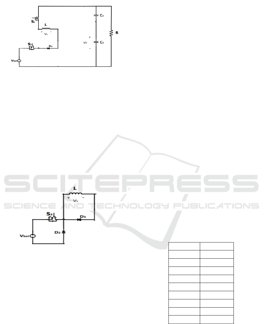
Fig 11
1) Time interval D1T <t<D2T:
In this state, Sb is off and the inductor's voltage is
set to Vbat. The inductive energy is lost in the battery
due to the opposing direction of the inductance and
battery voltages, and the current flowing through the
inductor decreases linearly as a result. The voltage
across the inductance is:
V
L
=-V
bat
The average voltage of the inductor in a period
must be zero, so:
D
0
(V
0
-V
bat
)T+(1-D
0
)(-V
bat
)T=0
V
bat
=D
0
V
o
Fig 12
3.PROPOSED CONTROL
STRATEGY
The DC reference voltage (𝑉
∗
𝑑𝑐
) is provided
below is calculated with the help of reference speed.
V
*
dc =
k
v
w
*
The reference voltage (𝑉
∗
𝑑𝑐
) is compared with the
actual load voltage (𝑉
𝑑𝑐
) and the error voltage (𝑉
𝐸
) is
provided below as
V
E
= V
*
dc
- V
dc
The generated error is given to proportional–
integral (PI) control, which provides the reference
voltage 𝑉
𝐶
as follows
V
C
(k) = V
C
(k - 1) + K
P
{V
E
(k) – V
E
(k – 1)} + K
i
V
E
(k)
The pulses generated for the boost converter is as
follows
{If 𝑀
𝐶
< 𝑉
𝐶
gating pulse is HIGH}
{If 𝑀
𝐶
≥ 𝑉
𝐶
gating pulse is LOW}
Fuzzy Logic Controller
An approach to thinking that mirrors human
reasoning is fuzzy logic. The strategy mimics how
humans make decisions, which require considering
all middle options between the digital signals YES
and NO. Despite the fact that fuzzy logic (FL) may
not produce accurate thinking, it is beneficial
nonetheless. The FL's architecture is broken down by
modules that convert system inputs into fuzzy sets.
Another module that contains rules supplied by the
user's IF-THEN statements. a fuzzy inference engine
that uses IF-THEN rules and fuzzy interpretation on
the inputs to emulate human reasoning.
Defuzzification is a different module that converts the
fuzzy set acquired by the interfering engine into a
crisp value. The membership function operates on
sets of variables that are ambiguous. A fuzzy set can
be graphically represented and linguistic terms can be
quantified using membership functions. Simple
model parameters can be utilised because complex
functions do not increase output precision.
Table I. Knowledge based rules
E
Output
NVL
PS
NL
Ps
NM
PS
NS
PS
Zero
PM
PS
PM
PM
PM
PL
PL
PVL
PVL
When the error, is negative, the measured voltage
is higher than reference voltage, then the fuzzy
controller will provide Low as output and when the
error is positive, the measured voltage is lower than
the reference voltage, then the fuzzy controller
increases the duty ratio (D).
ISPES 2023 - International Conference on Intelligent and Sustainable Power and Energy Systems
28
4.SIMULATION SETUP &
RESULTS
The simulation parameters for the proposed
inverter are provided below in Table II:
TABLE II Simulation Parameters
Input
Voltage
150 V
Input
power
6KW
Switching
Frequency
10
KHZ
Inductor
10µH
Coupling
Capacitor
50µF
Output
Capacitor
30µF
Battery
voltage
180V
Battery
capacity
100Ah
DC
Motor
parameters
600V,
6KW,
1500 rpm
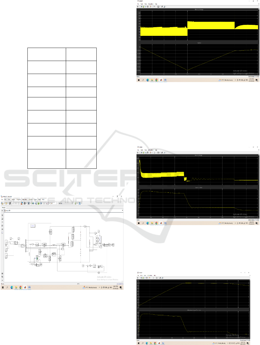
The simulation circuit of the bidirectional converter
with PI controller is provided below:
Fig 13 Simulation circuit of 3 leg 5 level inverter
The battery is discharging and provides supply to
the motor load (mode 1) from t=0 to 0.2s. The dc
voltage source is connected at t=0.2s and provides
supply to both motor and battery (mode2).
Regenerative braking is applied to the motor at t=0.4s
and energy stored in motor windings is fed back to
battery (mode 3). The battery voltage and %SOC is
provided below:
Fig 14
In this, battery is discharging in mode1 and the
%SOC is reducing until t=0.2s and in mode 2, the
battery is getting charged from dc voltage source and
hence %SOC starts to increase and at t=0.4s, the
regenerative braking is applied and the %SOC
continues to increase. The load voltage and current is
provided below:
Fig 15
During modes 1 and 2, the current flow is positive
i.e. in forward direction and in mode 3, the current
flow is reversed due to regenerative braking. The
motor speed and torque is provided below:
Fig 16
Bidirectional DC-DC Converter For Electric Vehicle Application Using FLC Controller
29

The speed is settled at t=0.2s in the set speed or
reference speed with PI controller. The PI controller
is replaced with fuzzy control and the speed and
torque is as provided below:
Fig 17
In this, the speed is settled at t=0.05s which is 4
times less than that of with PI controller.
A hardware prototype model of proposed
converter with input voltage of 24V, 50 Hz is
developed with 12V as battery voltage and output
voltage of 64V with load resistance of 1KΩ. The
hardware parameters is provided below in the
following Table III.
TABLE III Hardware Parameters
IRF 250N
MOSFET
200V,30A
U1560-DIODE
200-400-
600V,15A
CAPACITOR
1000 µF,
25V
TRANSFORMER
12V,1A
TLP 250- DRIVER
IC
12V,1.5A
CD 4050 BUFFER
IC
3-
18V,0.32mA
12V
REGULATOR 7812
12V,1A
IN 4007 DIODE
700V,1A
ARDINO UNO
CONTROLLER
7-
12V,20mA
Arduino uno control is used for generating the
pulses for the proposed converter and it is provided to
driver circuit (TLP 250) in order to drive the mosfets
IRF 250. The source voltage from the rectifier is
provided in the following waveforms:
Fig 18
In this the source1 voltage is around 22V and the
battery voltage is provided below:
Fig 19
In this, the battery will be charging when source1 is
available and when source1 is not available, the
battery starts discharging and provides energy to the
load. The load voltage is provided below:
ISPES 2023 - International Conference on Intelligent and Sustainable Power and Energy Systems
30

Fig 20
The load voltage of the proposed converter is around
64V.
5. CONCLUSION
In this, a bidirectional converter is designed with
multiple input multiple output and the modes of
operation of the proposed converter was analysed. A
control structure is formulated to reduce the voltage
distortions caused by varying loading conditions. A
switched capacitor cell is used to increase the voltage
conversion ratio. In my work we are compared
Proportional Integral (PI) controller and Fuzzy Logic
controller (FLC) in terms of speed of electric vehicle,
peak overshoot, settling time and torque ripples. After
comparing we come to know that Fuzzy Logic
controller is better than Proportional Integral
Controller, as the speed is 4 times increased than PI
controller. The regenerative braking is applied and
the energy from motor load is fed back to battery and
charges the battery. A hardware prototype model was
developed and the operation of the proposed
converter is verified with the results.
REFERENCES
S. Mohammadsalehian, F. Sedaghati, R. Eskandari and E.
Shokati Asl, "A Modified Double Input Z_source
DC_DC converter for Standalone PV/Battery System
Application," in Proc. 11th International Power
Electronics, Drive Systems and Technologies
Conference (PEDSTC), Tehran, Iran, 2020, pp. 1-7.
T. sharifi, A. Haji Biglo, M. Mirsalim, S. Farzamkia and J.
S. Moghani, "An asymmetrical cascaded single-phase
quasi Z source multilevel inverter with reduced number
of switches and lower THD," in Proc. 11th International
Power Electronics, Drive Systems and Technologies
Conference (PEDSTC), Tehran, Iran, 2020, pp. 1-5.
F. Sedaghati, S. Mohammadsalehian, H. Shayeghi, and E.
S. Asl, " A configuration for double input Z-source DC-
DC converters," 9th Annual Power Electronics, Drives
Systems and Technologies Conference (PEDSTC),
Tehran, Iran, 2018, pp. 449-455.
Haji Biglo, S. Farzamkia, S. Farhangi and H. Iman Eini,
"Utilization of Soft-Switched Boost Converter
for MPPT Application in Photovoltaic Single-
Phase Grid-Connected Inverter," in Proc. 11th
International Power Electronics, Drive Systems
and Technologies Conference (PEDSTC),
Tehran, Iran, 2020, pp. 1-6.
S. H. Hosseini, R. Ghazi, S. Farzamkia and M. Bahari, "A
Novel High Gain Extendable DC-DC Bidirectional
Boost-Buck Converter," in Proc. 11th International
Power Electronics, Drive Systems and Technologies
Conference (PEDSTC), Tehran, Iran, 2020, pp. 1-6.
Ansari, P. Cheng, and H.-J. Kim, "A 3 kW Bidirectional
DC-DC Converter for Electric Vehicles", Journal of
Electrical Engineering Technology, vol. 11, no. 4,
pp. 860-868, 2016.
S. Rezayi, H. Iman-Eini, M. Hamzeh, S. Bacha, S.
Farzamkia, ”Dualoutput DC/DC boost converter
for bipolar DC microgrids”, IET Renewable Power
Generation,vol.13, pp.1402-1410, 2019.
B. V. Kumar, R. K. Singh, and R. Mahanty, "A modified
non-isolated bidirectional DC-DC converter for
EV/HEV's traction drive systems," in 2016 IEEE
International Conference on Power Electronics,
Drives and Energy Systems (PEDES), 2016, pp. 1-
6.
E.Babaei, O.Abbasi, “Structure for multi-input multi-
output dc–dc boost f converter”, IET Power
Electron., vol.12, pp. 1-11,2015.
F. Sedaghati, S. Mohammadsalehian, H. Shayeghi, and E.
S. Asl, " A configuration of double input Z-source
DC-DC converter for standalone PV/battery system
application," Journal of Energy Management and
Technology, 2(3), pp.60-69.
Bidirectional DC-DC Converter For Electric Vehicle Application Using FLC Controller
31
