
Design of Single-Phase AC DC AC Bidirectional Three-Arm
Converter with Reduced Switches
Sonali N Borkade
1 a
And M. S. Aspalli
1 b
1
Department of Electrical and Electronics Engineering, Poojya Doddappa Appa College of Engineering, Kalaburagi
(affiliated to VTU Belgaum), Karnataka, India
Keywords: Three-Level Unidirectional MLI, AC DC AC Conversion, Bidirectional Power Flow Capability, Reduced
Components, and T-Type Inverter.
Abstract: The paper proposes a 1ф unidirectional five-level three arm inverter. It is comprised of a T-Type arm in the
output side with bidirectional capability. The proposed inverter provides the voltage with regulation of
magnitude and frequency. It also provides better power quality in terms of Total Harmonic Distortion and
power factor, and also reduces the number of components as we are using shared arms or leg. The space-
vector PWM strategy was designed in order to increase the performance and also to get 5 level output at both
ends and also eliminates the unbalance caused in the DC-link due to the DC capacitance with midpoint
connection. The simulation is carried out in MATLAB/Simulink 2018b version software.
1 INTRODUCTION
Due to applications like Active Power Filters (APF),
and Uninterruptible Power Supply (UPS), Unified
Power Quality Conditioners (UPQC), fascinate in 1ϕ
AC-AC converters have considerably expanded
recently. These converters supply steady ac voltage to
serve essential loads including computers,
telecommunication systems, and biomedical
instruments. They also deliver sinusoidal source
currents with unity power factor (N. B. de Freitas
2018). The three-leg six-switch converters have been
employed as a less expensive option to a four-leg
arrangement in the aforementioned applications. This
structure offers identical voltage capacity as its four-
leg equivalent when the input and output voltages are
at the same frequency (N. Rocha 2018). Numerous
three-leg configurations are being suggested in the
literature as a result of these properties. It was
suggested to use a unidirectional, single-phase, three-
leg AC-DC-AC converter (Wang 2020).
Comparing this design to a three-leg converter, it
is more effective and less expensive (referred to as a
3L2D converter)
(Sandeep 2019)
. The rise in
a
https://orcid.org/0009-0000-8084-3937
b
https://orcid.org/0000-0002-5483-6415
harmonic distortion is its lone flaw. Three-legged
converters have also been used with multilevel
topologies. These topologies combine the shared leg's
ability to minimise switch count with the key
advantages of multilevel systems, including reduced
voltage strain across the power components,
minimum switching losses, and less harmonic
distortion. For unidirectional applications, the
multilevel three-leg topologies cascaded, and parallel
3L2D converters are all appropriate (K. Yadav
2019). Due to its simplicity, the suggested topology—
referred to here as converter 3LNPC2D—is of
particular importance. Based on the unidirectional
leg, it is more efficient and retains all the benefits of
its bidirectional form despite having just 10 active
switches. The 3LNPC2D converter's primary
drawback is the more number of components in the
current path, which maximizes the conduction losses
(Lopez 2017). The application of this finding to the
3L2D and 3LNPC2D converter is possible.
Therefore, the ordinary 3L2D converter is
unquestionably the best option when performance is
the primary criterion for selection. T-type inverters
are often used in industrial settings, including
automated and renewable energy systems. There are
just four switches in a 3-level T-type leg, which
combines the satisfaction of minimal conduction
losses with excellent output voltage quality. T-type
inverters have therefore been the subject of extensive
N Borkade, S. and Aspalli, M.
Design Of Single-Phase AC DC AC Bidirectional Three-Arm Converter With Reduced Switches.
DOI: 10.5220/0012507300003808
Paper published under CC license (CC BY-NC-ND 4.0)
In Proceedings of the 1st International Conference on Intelligent and Sustainable Power and Energy Systems (ISPES 2023), pages 67-73
ISBN: 978-989-758-689-7
Proceedings Copyright © 2024 by SCITEPRESS – Science and Technology Publications, Lda.
67

investigation in the literature. The T-type inverter
evolved from having four levels to having n levels.
These were known as nested multilevel converters
because the central points of the limbs are connected
to the same spot. T-type inverters are being used with
different multilevel topologies to enhance the number
of levels. For instance, a T-type leg can be used to
create a nine-level inverter. A T-type inverter may be
used to combine a wide range of hybrid topologies.
There hasn't been much research done on using a T-
type converter for single-phase ACDC-AC
conversion.
Determining a single-phase T-type unilateral AC-
DC-AC converter is the goal of this work. A
unidirectional T-type arm and 2 bidirectional T-type
arms make up the suggested converter. A typical two-
level leg forms the T-type leg, which is connected to
the DC-link midway by an active bidirectional
switch. The bidirectional switch can be implemented
in several ways.
In this paper, two switches are connected with
common source or emitter and create a bidirectional
switch which is used in proposed 3 leg 5 level
inverter. The new inverter possesses minimized
number of switches compared to other traditional
multilevel inverters of same levels with bidirectional
capability. Due to this and improved performance
based on power quality, it can be utilized in
uninterruptible power supplies and active filters.
2 SYSTEM IMPLEMENTATION
Figure 1: Modified system block diagram.
The block diagram of the new inverter is given below
in Figure 1. AC voltage source is provided to the
proposed AC-AC converter which operates based on
the reference voltage provided to the controller. The
output voltage and DC-link voltage is given back to
controller and based on the modulation signal,
SVPWM pulse generator provides the pulses to the
converter. It is also possess bidirectional capability so
that the path of power flow can be reversed. The
modified converter consists of five-level
unidirectional and bidirectional voltage arms, DC-
link capacitor bank (C
01
and C
02
) and filters.
The unidirectional leg is composed of q
l
and q
̅
l
and
by the bidirectional switch q
l3
. By this, we can able to
achieve power flow from grid to load and load to grid.
The proposed 5 level 3 leg T-type inverter is given
below in Figure 2:
Figure 2: Proposed 5-level Inverter.
Modes 1, 2 and 3 are for positive half cycle of
voltage supply and modes 4, 5 and 6 are for negative
half cycle.
Mode 1:
In this mode, the inductor L
g
gets charged as the
switches q
p
and q
s
is turned ON. The load is supplied
from the energy stored in C
l
. The operational circuit
for mode 1 operation is given below in Figure 2 (a):
Figure 2(a): Mode 1 circuit of 5-level T-type inverter.
Mode 2:
In this mode, q
p
and q
l3
are turned ON. The inductor
L
g
discharges and charges the capacitor C
o1
along
with supplying the load. The load voltage is around
V
g
+V
ind
-V
co1
. The operational circuit for mode 2
operation is given below in Figure 2(b):
ISPES 2023 - International Conference on Intelligent and Sustainable Power and Energy Systems
68

Figure 2(b): Mode 2 circuit of 5-level T-type inverter.
Mode 3:
In this mode, q
p
and q
l
are turned ON. The inductor
L
g
discharges and supplies the load. The load voltage
is around V
g
+V
ind
. The operational circuit for mode 3
operation is given below in Figure 2(c):
Figure 2(c): Mode 3 circuit of 5-level T-type inverter.
Mode 4:
In this mode, the inductor L
g
gets charged as the
switches q
p
and q
s
is turned ON. The load is supplied
from the energy stored in C
l
. The operational circuit
for mode 4 operation is given below in Figure 2(d):
Figure 2(d): Mode 4 circuit of 5-level T-type inverter.
Mode 5:
In this mode, q
p
’ and q
l3
’ are turned ON. The inductor
L
g
discharges and charges the capacitor C
o2
along
with supplying the load. The load voltage is around –
(V
g
+V
ind
-V
co2
). The operational circuit for mode 5
operation is given below in Figure 2(e):
Figure 2(e): Mode 5 circuit of 5-level T-type inverter.
Mode 6:
In this mode, q
p
’ and q
l
’ are turned ON. The inductor
L
g
discharges and supplies the load. The load voltage
is around –(V
g
+V
ind
). The operational circuit for
mode 6 operation is given below in Figure 2(f):
Figure 2(f): Mode 6 circuit of 5-level T-type inverter.
3 PROPOSED CONTROL
STRATEGIES
To synchronise the grid side and load side, a control
circuit is suggested for regulating the capacitor
voltages. The control scheme has a series framework,
with an exterior loop in charge of adjusting the
electrical grid current reference i
g
and an inner loop
in charge of adjusting the voltage at the DC link V
C
=
V
C01
+ V
C02
. A PI regulator controls the reference grid
current's amplitude and modifies V
C
to match its
reference value. Since the converter's power flow is
unidirectional in nature the control method should be
able to eliminate the distortion caused by the input
current zero-crossing.
This issue is resolved by using a PLL (Phase Lock
Loop Technique) to synchronise the grid current i
g
relative to the rectifier voltage v
g
. The topology can
nevertheless function using a power factor that is near
to unity because the shift angle among e
g
and v
g
is so
tiny. With respect to Ig* and g, the block Gig specifies
the grid current reference as i
g
= I
g
sin g. Resonant
control (R
g
) was utilised to modify ig to match its
reference. The block G v
l
, i.e., v
l
= Vl sin g,
establishes a reference voltage using v
l
and g.
Design Of Single-Phase AC DC AC Bidirectional Three-Arm Converter With Reduced Switches
69

It only operates when the load voltage is in phase
with grid voltage with reduced magnitude and also by
balancing the dc capacitor voltages v
C01
and v
C02
.
Figure 3: Proposed control strategy for three-leg five-level
T-type inverter.
The reference load voltage and grid voltage can be
incorporated using SVM strategy. The space-vector
plane for the proposed inverter is given below in
Figure 4.
Figure 4: Switching states of proposed inverter.
From above figure, there are nine active switching
vectors (V
1
→ V
10
), eight sectors in additional with a
null vector (V
0
). The vectors are provided in the
equation shown below:
V
*
k
g,
k
l,
k
s
= v
g
*
+ jv
l
*
Where, the inconsistencies can be expressed as V
k
g
, k
l
, k
s
, where k
g
, k
l
, and k
s
represent the switching
phases of arms g, l, and s, respectively. The grid and
load voltages correspond towards the real (Re) and
imaginary (Im) axes, respectively. There are
opportunities to create the model vector V since there
are duplicate switching states. The switching patterns
are intended to balance the imbalance brought on
through the DC-link mid-point interconnection and
minimise the loss of power (conduction and switching
losses).
The reference vector must be incorporated as:
V
*
= V
X
𝑡1
𝑇𝑠
+ V
y
𝑡2
𝑇𝑠
+ V
z
𝑡3
𝑇𝑠
In the above equation, t
1
, t
2
and t
3
are time weights
for the vectors V
x
, V
y
and V
z
, respectively, and the
switching cycle time is defined by Ts = t
1
+t
2
+t
3
. The
time weights are determined using the following
relation:
4 SIMULATION FRAMEWORK &
OUTCOME
The simulation parameters for the modified inverter
are provided below in Table 2:
Table 2: Simulation Parameters.
Input Voltage
110 Volt
Output Voltage
210 Volt
Frequency
50 HZ
Output power
100 Watt
Load Resistance
100 Ohm
The simulation circuit is given below in Figure 5.
Figure 5: Simulation circuit of 3-leg 5-level inverter.
Here, the input AC voltage of 110 Volt is connected to
the modified inverter which boosts up to 210V and
provided to the resistive load of 100Ω. It consists of 8
ISPES 2023 - International Conference on Intelligent and Sustainable Power and Energy Systems
70

switches including a bidirectional switch. The pulses
generated from the s pulse generator are provided below in
Figure 6.
Figure 6: Switching Pulses of proposed inverter.
The output voltage and current along with power is given
below in Figure 7.
Figure 7: Output voltage, current and power waveforms of
3-leg 5-level inverter.
The peak output voltage is around 210V and the
current is around 0.6 A with power is around 106VA.
The %THD of the load current is given below in
Figure 8.
Figure 8: %THD of modified inverter.
The %THD of the load current is around 4.7%.
The power factor measured at the input side is given
below in Figure 9.
Figure 9: Power Factor of proposed system.
The power factor is around 0.964.
A hardware prototype of modified inverter with
input voltage of 12V, 50 Hz is developed with 24V as
load voltage with load resistance of 100 ohm. The
hardware parameters are given below in the following
Table 3.
Table 3: Hardware Parameters.
IRF 250N MOSFET
200Volt, 30A
U1560-Diode
200-400-600Volt, 15A
Capacitor
1000μF, 25Volt
1000μF,100Volt
Transformer
12Volt, 1A
TLP-250 Driver IC
12Volt, 1.5A
CD 4050 Buffer IC
3-18Volt, 0.32mA
12V Regulator 7812
12Volt, 1A
IN 4007 Diode
700Volt, 1A
Arduino UNO
controller
7-12Volt, 20mA
The load voltage division setting is 20V/div for
the above voltage waveforms.
Arduino UNO control is used to produce the
pulses for the modified inverter and it is given to
driver circuit (TLP 250) in order to navigate the
MOSFETs IRF 250. The five-level three-leg inverter
voltage is given below in Figure 10.
Design Of Single-Phase AC DC AC Bidirectional Three-Arm Converter With Reduced Switches
71
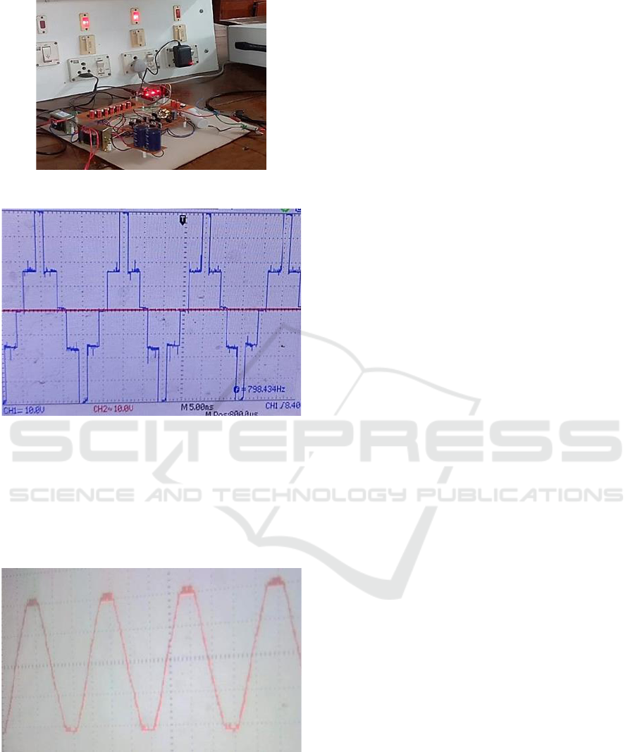
Figure 10: Five-level three-leg inverter voltage.
Figure 11: Load voltage with Capacitor filter.
In the above waveform, in positive cycle, two
levels (one level is Vdc-Vc1 and second level is Vdc)
and in negative cycle two levels and with zero level
we get five-levels.
The load voltage with C filter is given below in
Figure 12.
Figure 12: Hardware framework of modified system.
5 CONCLUSIONS
Here, a 5-level 3 leg T-type inverter with bidirectional
power conduction capability is designed and the
modes of operation of the modified inverter was
explored. A control structure is formulated to reduce
the voltage distortions caused by DC-link capacitors.
A space vector modulation based switching stategy is
followed to reduce the unbalances and therby reduce
the harmonics as well as system losses. In this, the
power factor is measured as 0.964 and the %THD is
around 4.7% for the R load of 100 ohm. A hardware
model is designed and the output voltage waveforms
with and without filter is verified. The main
advantage and applications of proposed AC-DC-AC
converter are it possesses minimum number of
switches and hence the losses will be low. In
reference paper [1] total number of switches is ten,
and here in this work it is reduced to eight. It is
capable of bidirectional power flow; it can be used in
AC drives with regenerative braking capability. It
also possesses voltage boosting capability.
REFERENCES
N. B. de Freitas, C. B. Jacobina, N. S. de Moraes Lima
Marinus, and N. Rocha, “AC-DC-AC single-phase
multilevel six-leg converter with a reduced number of
controlled switches,” IEEE Transactions on Power
Electronics, vol. 33, DOI
10.1109/TPEL.2017.2707064, no. 4, pp. 3023– 3033,
Apr. 2018.
N. Rocha, A. E. L. da Costa, and C. B. Jacobina, “Parallel
of two unidirectional AC-DC-AC three-leg converters
to improve power quality,” IEEE Transactions on
Power Electronics, vol. 33, DOI
10.1109/TPEL.2017.2771464, no. 9, pp. 7782–7794,
Sep. 2018.
B. Wang, Z. Li, Z. Bai, P. T. Krein, and H. Ma, “A
redundant unit to form T-type three-level inverters
tolerant of igbt open-circuit faults in multiple legs,”
IEEE Transactions on Power Electronics, vol. 35, DOI
10.1109/TPEL.2019.2912177, no. 1, pp. 924–939, Jan.
2020.
N. Sandeep and U. R. Yaragatti. “A Switched-Capacitor-
Based Multilevel Inverter Topology with Reduced
Components,” IEEE Trans. Power Electron.,
vol
.
33
,
no.7, pp. 5538-5542. Jul. 2018.
K. Yadav, K. Gopakumar, K. R. R, L. Umanand, S.
Bhattacharya, and W. Jarzyna, “A hybrid 7-level
inverter using low-voltage devices and operation with
single dc-link,” IEEE Transactions on Power
Electronics, vol. 34, DOI
10.1109/TPEL.2018.2890371, no. 10, pp. 9844–9853,
Oct. 2019.
I. Lopez, S. Ceballos, J. Pou, J. Zaragoza, J. Andreu,
E. Ibarra, and G. Konstantinou, “Generalized pwm-
based method for multiphase neutral-point-clamped
converters with capacitor voltage balance capa- bility,”
ISPES 2023 - International Conference on Intelligent and Sustainable Power and Energy Systems
72

IEEE Transactions on Power Electronics, vol. 32, no.
6, pp. 4878–4890, June 2017.
R. Teichmann, S. Bernet, “A comparison of three-level
converters versus two-level converters for low-
voltage drives traction and utility applications,”
IEEE Trans. Ind. Appl.,
vol. 41,
no. 3, pp. 855-865,
Jun. 2005.
R. S. Kanchan, M. R. Baiju, K. K. Mohapatra, P. P.
Ouseph, and K. Gopakumar, “Space vector PWM
signal generation for multilevel inverters using only the
sampled amplitudes of reference phase voltages,” IEE
Proceedings - Electric Power Applications, vol. 152,
no. 2, pp. 297– 309, March 2005.
Q. Xu, F. Ma, A. Luo, Z. He, and H. Xiao, “Analysis
and control of M3C-based UPQC for power quality
improvement in medium/high- voltage power grid,”
IEEE Transactions on Power Electronics, vol. 31, pp.
8182–8194, Dec 2016.
C. B. Jacobina, N. Rocha, N. S. Marinus, and E. C. Santos,
“AC-AC single-phase dc-link converter with four
controlled switches,” in Applied Power Electronics
Conference and Exposition (APEC), 2012 Twenty-
Seventh Annual IEEE, pp. 1927–1932. IEEE, 2012.
O. Kwon, J.-M. Kwon, and B.-H. Kwon, “Highly efficient
single-phase three-level three-leg converter using sic
mosfet s for ac–ac applications,” IEEE Transactions on
Industrial Electronics, vol. 65, no. 9, pp. 7015– 7024,
2018.
Design Of Single-Phase AC DC AC Bidirectional Three-Arm Converter With Reduced Switches
73
