
Automatic Bottle Filling And Capping System
Kaushik N Tupsakri
1 a
, Harsha R Gowda
1 b
, Kaling Taluru V
1 c
Manjunath M
1 d
and Shruti R Gunaga
1 e
Department of Electrical & Electronics Engineering. Dayananda Sagar College of Engineering, Bengaluru, India
shruthirg-eee@dayanandasagar.edu
Keywords: stepper motor, solenoid valve, DC motors.
Abstract: The main aim of the proposed system is to fill the bottles of varying volumes with two different liquids
according to user input and automatically cap the filled bottles of different volumes on a single assembly and
dispense it. The entire operation of the proposed system is controlled by the means of Arduino. The proposed
system makes use of a rotating mechanism to rotate the bottles and the rotating mechanism is driven by a
stepper motor. The bottles are filled through a solenoid valve using a water pump. For the capping of bottles
of different volumes two DC motors are used and capping is done by linear mechanism. Finally, the bottles
are dispensed using a conveyor belt driven by a motor.
1. INTRODUCTION
In the packaging sector, filling machines are crucial
pieces of equipment used to put Liquids, gases,
pastes, or powders into containers. The material-
filled bottles are capped using capping machines.
Most companies provide a selection of items. For
instance, a beverage manufacturing firm could
create bottles of different capacities, such as 200ml,
250ml, and 300ml. To make these bottles, the
manufacturers use several assembly lines that are
tailored for different quantities (Patil, M. D. (2021).
As a result, there are more assembly lines, which
means there are more components, which raises the
cost of setup. Additionally, each manufacturing line
must have its own electrical supply and be
monitored independently. The labour cost and
operational costs go up as a result. Most
manufacturing organisations now employ the just-
in-time production principle as a result of the arrival
of 21st-century economics (Abashar, A.et al.,2017).
This indicates that the businesses only manufacture
in small quantities that are determined based on
their previous and anticipated sales, rather than
producing the goods in large quantities and storing
them. In the previously mentioned scenario, if the
firm does not experience 300ml bottle sales,
producing such bottles would be worthless since the
company would suffer losses if they did so. As a
result, they would stop producing those bottles
(Pannu et al.,2016)
The assembly line's original setup for 300ml bottles
would now be pointless, increasing losses. The
proposed system overcomes this problem by filling
bottles of varying volumes based on the
manufacturer’s requirement for their wide range of
products (Murali, Y. N. 2012). The system allows
them to scale up and scale down based on their
business model requirement. The system makes use
of solenoid valves and water pumps for the filling
of bottles along with a capping system using a
motorised arrangement all integrated in a single
machine(Zhang, P. 2008).
2. HARDWARE
IMPLEMENTATION
The filling and capping systems are integrated
into a single mechanism and connected to Arduino
to make the whole mechanism automatic. The
Proposed system operated based on the user
requirements. The user gives the input using a
keypad that is connected to Arduino.
2.1 STEPPER MOTOR:
Stepper Motor is used to drive the rotating
mechanism which is used to rotate the bottles of
different mechanisms. The stepper motor is
operated by using a 12-volt DC supply.
a
https://orcid.org/0009-0009-0022-8471
b
https://orcid.org/0009-0001-4717-9285
c
https://orcid.org/0009-0006-4650-1128
d
https://orcid.org/0009-0002-0911-8147
e
https://orcid.org/0009-0000-9258-5410
2.2 SERVO MOTORS:
Servo motors are used for pushing mechanisms which
push the bottles of different volumes onto the rotating
N Tupsakri, K., R Gowda, H., Taluru V, K., M, M. and R Gunaga, S.
Automatic Bottle Filling And Capping System.
DOI: 10.5220/0012507800003808
Paper published under CC license (CC BY-NC-ND 4.0)
In Proceedings of the 1st International Conference on Intelligent and Sustainable Power and Energy Systems (ISPES 2023), pages 177-182
ISBN: 978-989-758-689-7
Proceedings Copyright © 2024 by SCITEPRESS – Science and Technology Publications, Lda.
177
mechanisms. Servo Motors are also used for
dispensing the filled bottles. These servo motors are
operated by 5-volts DC supply.
2.3 SOLENOID VALVE:
Solenoid valves are used to fill the bottles with two
different liquids and cut off the water flow
automatically when the bottles are filled. It is
operated by the 12-volt DC supply.
2.4 INFRARED SENSORS:
IR Sensors are used to sense the starting point on the
rotating mechanism and send the signal to Arduino to
start rotating. Automatic Bottle Filling And Capping
System and to sense the bottles which are to be filled
and to sense the bottles which are to be capped.
2.5 PUMPS
Pumps are used to pump the liquids to fill the bottle
through a solenoid valve. Two pumps are used for
pumping two different Liquids. Pumps are operated
using a DC motor driven by a 12-volt DC supply.
.
2.6 DC MOTORS
DC motors are used for capping mechanisms which
are driven by a 12-volts DC supply. The capping is
done by a linear mechanism. DC motor is also used
for driving the conveyor belt
.
2.7 CONVEYOR BELT
The conveyor belt is used to dispense the filled and
capped bottles of varying volumes. The conveyor belt
is driven by a DC motor whose speed is controlled
.
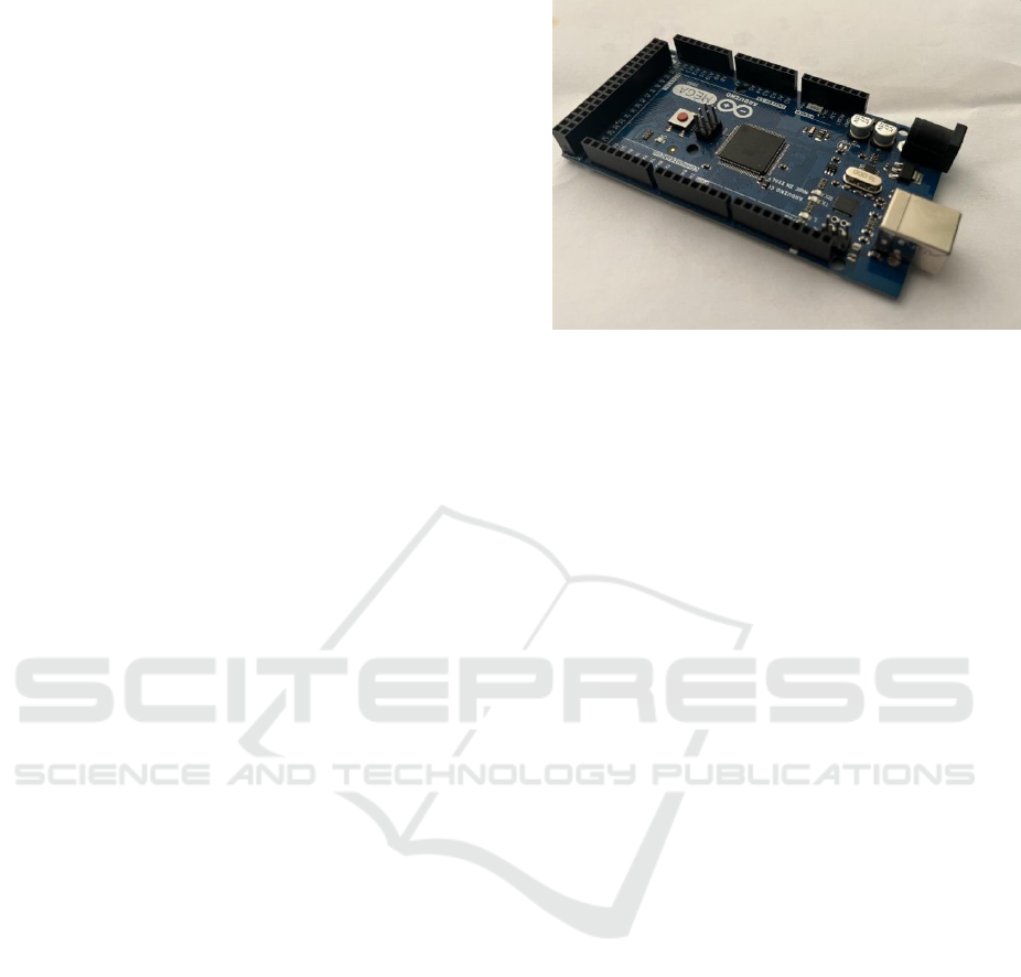
2.8 MICROCONTROLLER
The microcontroller used in the proposed system
is Arduino Mega. It has 54 digital input/output pins
and 16 analog input pins, 4 UARTs and a 16 MHz
crystal oscillator, a USB connection, a power jack, an
ICSP header, and a reset button. Here Arduino is used
to control the operation of the system and take input
from the user and operate all the sensors and automate
the whole system.
Fig 1. Arduino Mega microcontroller
3.METHODOLOGY
3.1 SYSTEM DESIGN
The proposed system uses Arduino Mega for
controlling and automating the system. The input for
Arduino for filling the bottles is given by the user
through a keypad that is connected to Arduino.
(Berger, H. 2012.).There is a pushing mechanism that
is operated by the servo motor, it pushes the bottle
onto the rotating mechanism. The rotating
mechanism is used for rating bottles for filling and
capping(Sidik, M., & Ghani, S. C. 2017). The bottles
are filled by using water pumps through the solenoid
valve. Then bottles are capped by using two DC
motors using a linear mechanism. And the bottles are
dispensed using the conveyor belt.
3.2 BOTTLE SELECTION
The user will be prompted at the beginning to indicate
how many 250 ml and 500 ml bottles should be filled
with water and how many should be filled with juice
since the proposed system can only fill these sizes
with two different liquids,such as water and juice.
The user will also be prompted to indicate how many
250 ml and 500 ml bottles should be filled with water
and juice. Users may input data via a keypad linked
to an Arduino, and the data is displayed on an LCD
screen.
3.3 BOTTLE PLACEMENT
After taking input from the user the system gets
started and there are two pushing mechanisms like
rack and pinion, one Automatic Bottle Filling And
Capping System for 250ml bottles and one for 500ml
bottles. The pushing mechanism pushes the bottle
ISPES 2023 - International Conference on Intelligent and Sustainable Power and Energy Systems
178
onto the rotating mechanism. These pushing
mechanisms are operated by servo motors.
3.4 FILLING PROCESS
After bottles are pushed onto the rotating mechanism
the rotating mechanism starts rotating, IR sensor
placed near the filling poles senses the bottle and
stops the rotating mechanism. The bottles are filled
with two different liquids based on the user input. For
filling the two different liquids two water pumps are
used and two solenoid valves are used.The water is
pumped to the bottle by a water pump that is operated
by a DC motor, through a solenoid valve. The filling
of the bottle is done based on time, after a certain time
when the bottle is filled the solenoid valve cuts off the
water supply.If the user needs two bottles of all types
then the system will fill the 250ml bottle with water
first and then the 250ml bottle with juice and then the
500ml bottle with water and at last the 500ml bottle
with juice (Chakraborty et al., 2015).
.
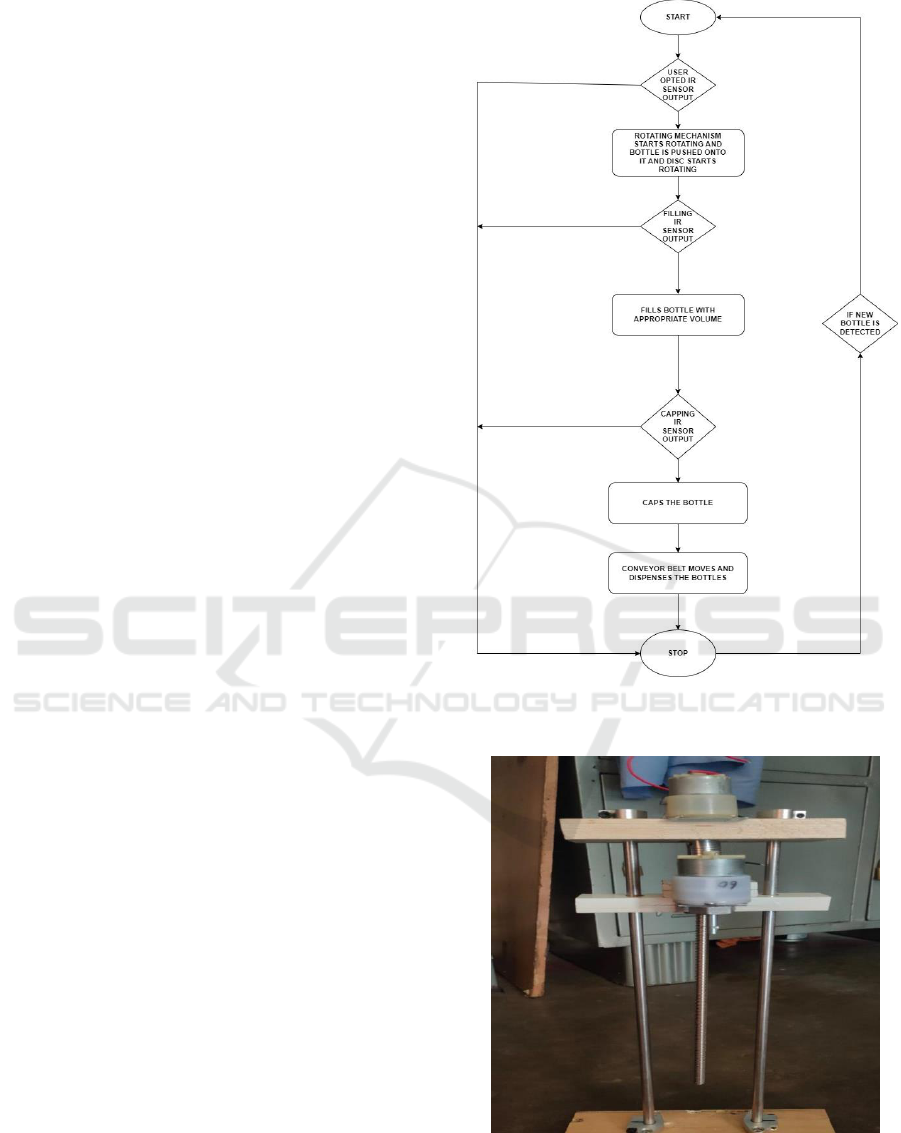
3.5 CAPPING PROCESS
After the bottles are filled with the respective liquids,
the rotating mechanism moves and the bottle takes the
cap from the stack, and an IR sensor placed at the
capping mechanism senses the bottle and stops the
rotating mechanism, then the bottles are capped by
using a linear mechanism in which two DC motors
are used. One DC motor is used to move another DC
motor UP and down, the other DC motor holds the
cap of the bottle and tightens it.
3.6 DISPENSING MECHANISM
Once the bottles are capped then the rotating
mechanism starts again and moves the bottle, then the
bottles are placed on the conveyor belt which is
operated using a DC motor. The conveyor belt moves
the bottle and dispenses it. The dispensing is done at
four 4 different places, 250ml bottle with water at one
place and 250ml bottle with juice at another place and
so on.
Fig 2. Process Flow of the System
Fig 3. Capping mechanism
Automatic Bottle Filling And Capping System
179

Fig 4. Conveyor Belt
4 BLOCK DIAGRAM
Fig 4. Block Diagram of the proposed system
The block diagram illustrates a proposed system that
automates the process of filling, capping, and
dispensing bottles. The system operates with
a12-Volt DC supply that powers a stepper motor
responsible for initiating the rotating
mechanism. As the rotating mechanism starts
moving, an IR sensor detects a specific point,
marking it as a reference. Once this point is
sensed, a rack and pinion mechanism is
activated, pushing 250ml and 500ml bottles onto
the rotating platform. Subsequently, the rotating
mechanism begins its rotation, and IR sensors
placed near a solenoid valve detect the presence
of bottles as they pass by. Upon sensing a bottle,
a pump is activated to pump the liquid into the
bottle through the solenoid valve. The type of
liquid to be filled is determined by the user input
and the amount of liquid to be filled is calculated
based on time. Once the bottle is filled, the
solenoid valve cuts off the liquid flow,
preventing overfilling. Continuing the rotation,
another IR sensor located near the capping
mechanism senses the presence of the bottle,
causing the rotating mechanism to stop. At this
point, the capping process begins, employing a
linear mechanism with two DC motors to secure
the caps onto the bottles. Once the capping is
complete, the filled and capped bottles are
dispensed using a conveyor belt, which is driven
by a DC motor. The conveyor belt transports the
bottles to four different dispensing points. The
system ensures that 250ml bottles of one type of
liquid are dispensed at one point, while 500ml
bottles of another liquid type are dispensed at
another point, and so on. This arrangement
facilitates organised and efficient bottle
dispensing. The system combines with an
Arduino controller to regulate and plan the
whole operation. The Arduino serves as the main
controlling component, allowing automation
based on user needs. This system's integration of
multiple parts and use of the Arduino's features
results in a simplified and automated method of
filling, capping, and distributing bottles in a way
that the user specifies (Mashilkar et al,2015).
5 CIRCUIT DIAGRAM
The above figure illustrates the circuit diagram of the
proposed system. The proposed system uses Arduino
Mega to control and automate the whole system. The
Arduino Mega
uses Atmega 2560 microcontroller. A keypad is
connected to Arduino to take the user input and LCD
ISPES 2023 - International Conference on Intelligent and Sustainable Power and Energy Systems
180
display is used to display the inputs given. The system
contains one stepper motor, five 5DC motors, and 5
servo motors. The servo motors are controlled by
Arduino mega and all servo motors are connected to
the digital pins of Arduino Mega (Badamasi, Y. A.
2014, September). To power the stepper motor and the
DC motors 12 volts of power supply. SMPS is used
as a 12 volts power supply for high current device that
is a stepper motor, a 12-volt 1-amp adapter is used for
operating the DC motor used for water pumps, and a
5-volt 1-amp adapter is used to power all servo
motors. The servo motors are operated by Pulse
Width Modulation (PWM). And to stop the DC
motors when needed these DC motors are operated
through relays. Eight IR sensors are used one for
recognizing the starting point on the rotating
mechanism, two IR sensors are used near solenoid
valves to sense and stop the bottles for filling, and two
sensors are used for capping. And rest of them is used
for the dispensing
process.A4988 stepper motor driver is used to operate
the stepper motor. The L298N motor driver is used to
drive the DC motor used for the capping mechanism
in both directions clockwise and anticlockwise. The
motor driver helps the DC motor to rotate in both
directions clockwise and anticlockwise. The
conveyor belt is operated using a DC motor whose
speed is controlled by the speed control circuit
6 ANALYSIS AND RESULT
Industries in the real world fill the bottle with
different volumes and different liquids in separate
assembly lines. This leads to the use of separate
control units, separate infrastructures, separate
motors, sensors, and separate software programs
which results in increased expenses for the company.
And industries use PLCs for automation and human-
machine interface which are expensive and increase
the spending costs of the company. The separate
assembly lines consume more power to operate and it
makes it difficult for the company to maintain the
assembly lines and the quality of products. Using this
increases the operational and labour cost of the
company. In case of fewer sales of one particular
volume of the bottle, the company has to shut down
the whole assembly line of that particular volume of
the bottle which makes the company face losses.
The proposed system overcomes all these problems
and makes the industries spend less money. The
proposed system fills the bottles of varying volumes
250ml and 500ml with two different liquids in a
single system. And the bottles are capped
automatically. This capping and filling mechanism is
integrated into a single system. And the proposed
system dispenses the filled capped bottle using a
conveyor belt at 4 different places and the system
operates as per user requirements by taking input
from the user. The system uses an Arduino Mega
microcontroller for controlling and automation
because it is cheaper than PLC. The whole system
operates on a single electrical supply. So the proposed
system can be more efficient and reliable for the
industries as the proposed system can make the
industries spend less money on the maintenance of
the system, using this system can maintain the quality
of products and decrease the operational and labour
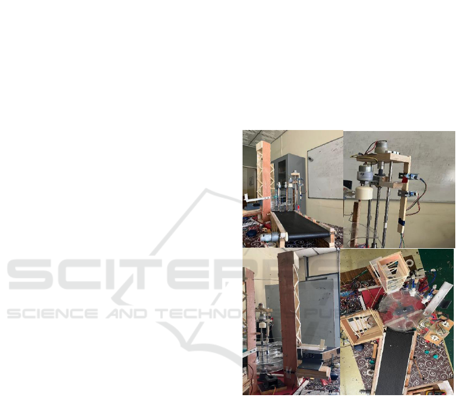
cost. The figures below show the working model of
the project.
Fig.7 Working Model
7 CONCLUSION
The method uses automated technologies to
streamline production and eliminate manual
work. The system can identify and control bottles
of various sizes, ensuring that each bottle receives
the right amount of liquid. The system's versatility
allows it to be used in a wide range of industries
and applications. Additionally, the likelihood of
contamination and cross contamination is
decreased by the automated filling and capping
process. Maintaining a high level of cleanliness
and avoiding the blending of liquids, it guarantees
Automatic Bottle Filling And Capping System
181

the integrity and quality of the filled bottles. This
feature is crucial for industries including
pharmaceuticals, food and beverage, and
cosmetics. The core of the system is its reliable
and sturdy design. The system is equipped with
state-of-the-art sensors, actuators, and control
mechanisms to ensure precise measurements and
smooth operation.
REFERENCES
Patil, M. D. (2021). Automatic Bottle Filling, Capping
And Labelling System Using Plc Based Controller.
Ilkogretim Online, 20(1), 5750-5761.
Abashar, A. I., Mohammedeltoum, M. A., & Abaker, O. D.
(2017, January). Automated and monitored liquid
filling system using PLC technology. In 2017
International Conference on Communication,
Control, Computing and Electronics
Engineering (ICCCCEE) (pp. 1-5). IEEE.
Pannu, J., Kulkarni, R., & Ranjana, M. S. B. (2016, March).
On the automated multiple liquid bottle filling system.
In 2016 International conference on circuit, power
and computing technologies (ICCPCT) (pp. 1-3).
IEEE.
Burali, Y. N. (2012). PLC based industrial crane
automation & monitoring. International Journal of
Engineering and Science, 1(3), 01-04.
Zhang, P. (2008). Sensors and actuators for industrial
control. Industrial Control Technology: A
Handbook for Engineers and Researchers, 120-
128.
.Berger, H. (2012). Automating with SIMATIC: controllers,
software, programming, data. John Wiley & Sons.
Somavanshi, A. P., Austkar, S. B., & More, S. A. (2013).
Automatic bottle filling using microcontroller
volume correction. International Journal of
Engineering Research and Technology IJERT, 2(3),
1-4.
Sidik, M., & Ghani, S. C. (2017). Volume measuring
system using arduino for automatic liquid filling
machine. International Journal of Applied
Engineering Research, 12(24), 14505-14509.
Chakraborty, K., Roy, I., De, P., & Das, S. (2015).
Controlling the Filling and Capping Operation of a
Bottling Plant using PLC and SCADA. Indonesian
Journal of Electrical Engineering and Informatics
(IJEEI), 3(1), 39-44.
Mashilkar, B., Khaire, P., & Dalvi, G. (2015). Automated
bottle filling system. International Research Journal
of Engineering and Technology (IRJET), 2(07), 771-
776.
Badamasi, Y. A. (2014, September). The working principle
of an Arduino. In 2014 11th international conference
on electronics, computer and computation (ICECCO)
(pp. 1-4). IEEE.
ISPES 2023 - International Conference on Intelligent and Sustainable Power and Energy Systems
182
