
Effective Multilevel Inverter with 129 Level Output
A. Annai Theresa
1 a
and S. Malathi
2 b
1
Anna University, SRM Valliammai Engineering College, Chennai, India
2
Department of Electrical and Electronics Engineering, SRM Valliammai Engineering College, Chennai, India
Keywords: Multilevel Inverter (MLI), 129 Level Asymmetrical Cascaded Multilevel DC Source Inverter (ASCMLDCSI),
Total Harmonic Distortion (THD), MATLAB/ SIMULINK.
Abstract: The multilevel inverter (MLI) is a power conversion scheme that provides the desired alternating current level
by utilizing numerous DC sources. Applications requiring medium to high power can use it. For getting a
pure sinewave in an effective manner, this paper showcases a 129-level asymmetrical cascaded multilevel DC
source inverter (ASCMLDCSI) with lower switching components and lower total harmonic distortion (THD).
Multiple DC sources with voltage ratios of 1:1:2:4:8:12:16 are used in the suggested inverter. To regulate the
switching components of the architecture, the suggested inverter employs a voltage reference approach. The
suggested topology has several advantages, including smaller switching components, fewer losses, and lower
THD. To simulate and analyse the performance of the suggested topology, MATLAB/SIMULINK software
is employed.
1 INTRODUCTION
Because of the benefits of high quality and clear
power output wave forms, low interference with the
electronic signals, low losses in switching, and
capability of withstanding high-voltage,
MULTILEVEL power conversion has grown in
popularity in recent years. A staggering amount of
semiconductor devices required is the fundamental
downside of this technique. Because lower-voltage
devices can be utilized, this does not result in a
considerable cost rise. However, we need a more
intricate mechanical architecture and more gate drive
electronics. Although the diode clamped multilevel
inverter has garnered a lot of attention in the
literature, the cascading or series-connected H-bridge
inverter topologies have received a lot of interest as
well [J. Rodríguez, 2002].
The primary benefit of this design is its simplicity,
as well as the possibility to cascade fewer or more H-
bridge cells to reduce or improve voltage and power
levels, respectively. The primary drawback of this
design is that a single H-bridge cell needs its own
independent DC supply. Separated sources are often
powered via a transformer/rectifier arrangement, but
a
https://orcid.org/0009-0004-5127-5140
b
https://orcid.org/0000-0001-7703-0281
they can also be powered by batteries, capacitors, or
photovoltaic arrays [K.T. Maheswari, 2021].
Robicon Group recently patented this topology in
1996, and it is now one of the company's regular drive
solutions. Utilizing distinct DC voltages on each
series H-bridge to expand the number of voltage
levels and enhance power quality is one of the most
recent advancements in cascaded H-bridge inverters.
Only in 1998 and 1999 was this invention granted
patent protection [Keith Corzine, 2002]. Then the
researchers started to develop a special kind of
inverters like cascading the H- bridge cells with the
ability to switch between more number of levels. The
cascading technology mushroomed in the research
field and the H- bridge inverters developed with a
large number of levels, less THD, minimum number
of drivers and switching components, simple
operational process, compact circuits, optimum
losses and improved efficiency. Not only the
cascading technology, but also some other techniques
were implemented in the process of the development
of multilevel inverter technology [P. Omer, 2020].
This paper is an effort to improve the quality of the
output waveform by increasing the output to 129
Theresa, A. and Malathi, S.
Effective Multilevel Inverter with 129 Level Output.
DOI: 10.5220/0012509100003808
Paper published under CC license (CC BY-NC-ND 4.0)
In Proceedings of the 1st International Conference on Intelligent and Sustainable Power and Energy Systems (ISPES 2023), pages 93-99
ISBN: 978-989-758-689-7
Proceedings Copyright © 2024 by SCITEPRESS – Science and Technology Publications, Lda.
93

levels and obtain the sinusoidal waveform with the
optimum number of constituents.
2 MULTILEVEL POWER
CONVERSION
The requirement to reduce the harmonic content of
inverter output voltage prompted the development of
multilevel power conversion technology. As a result,
it has been practically applied to meet the requirement
of implementing inverters driven by high voltage DC
buses. State-of-the-art switching devices have either
been overstressed or lack the necessary voltage rating
to implement high voltage and high power inverters.
Using multiple topologies reduces the demand on
switching devices correspondingly. As a result, huge,
lossless step-up/down transformers are not required
to manage high DC bus voltage levels [A. Ali, 2016].
The notion of multilevel is derived from the term
three-level, which produces three voltages (levels) in
relation to the capacitors' negative terminal.
Multilevel inverters are composed of an array of
power semiconductor devices and a number of
voltage sources, the output of which generates
voltages with varying waveform levels. Because of
the commutation of the switches, capacitor voltages
can be added, causing a large voltage to be produced
at the output whereas power semiconductors can only
sustain low voltages. By clamping the voltage at
different levels via clamping capacitors/diodes, a
number of voltage sources can be generated from a
single voltage source.
Multilevel inverters have some appealing
characteristics, including the ability to create output
voltage with tremendously low distortion and lower
rate of change of voltage i.e. dv/dt, draw input current
with awfully low distortion, and operate at a reduced
switching frequency. There are numerous ways to use
multilevel inverters, each having advantages and
disadvantages of its own. The most basic way
involves connecting standard inverters in series to
generate staircase waveforms [Ronak A. Rana, 2019].
The most prevalent use of multilevel inverters has
been in traction, including locomotives and drives.
Harmonic performance improved dramatically with
several switches and degrees of freedom. PWM
control is often used in multilevel inverters because
the output is almost a sine wave and hence has less
distortion. Multilevel inverters use different/complex
control/modulation approaches than three-level
inverters.
In the basic design, pulses are generated by
comparing the sine reference to multi-stack triangular
carriers. Multilevel inverters have shown to be an
excellent choice for high-power applications.
3 MULTILEVEL INVERTER
TOPOLOGIES
An overview of the topological structures that can be
utilized to produce multilevel waveforms is given in
this section. Topologies are roughly categorized into
seven groups based on fundamental structural
differences. In the following sections, representative
examples of single phase structures from each
category are displayed and described.
3.1 Concept of Multilevel Inverters
Multilevel inverters are utilized in situations
requiring high voltage/high power. The array of
power semiconductors that make up multilevel
inverters provides voltages with stepped waveforms
as its output. Switch commutation allows the
combination of capacitor voltages, resulting in a high
voltage at the output, whereas a power semiconductor
is represented by the perfect switch with multiple
positions. A two-level inverter generates an output
voltage with two levels in relation to the negative
terminal of the capacitor. Fig.1. (a), two levels, (b),
three voltages generated by the three-level inverter,
and so on [J. Rodríguez, 2002].
(a) (b)
(c)
Figure 1: With (a) two levels, (b) three levels and (c) “m”
levels the inverter’s one phase leg.
The number of voltage levels between two phases
of the load "m" equals m=2l+1 where "l" is the
number of phase voltage levels with respect to the
ISPES 2023 - International Conference on Intelligent and Sustainable Power and Energy Systems
94

inverter's negative terminal. Less harmonic distortion
is produced as a result of the inverter's increased level
count and increased step size of the output voltages.
On the other hand, a high level count increases
control complexity and results in voltage imbalance
issues. Cascaded multilevel inverters, diode-clamped
multilevel inverters, and capacitor-clamped
multilevel inverters are the three unique topologies
that have been suggested for multilevel inverters. The
two new entries holding the objective of reducing the
component count are cascaded sources and multilevel
DC-link [J. Rodríguez, 2002].
3.2 Types of Multilevel Inverters
The following are the most actively developed
topologies:
1. Multilevel cascaded inverter
2. Multilevel diode-clamped inverter
3. Multilevel inverter with flying capacitors
4. Cascaded sources multilevel DC-link inverter
(CSMLDCLI)
5. Multilevel DC-link inverter
3.2.1 Cascaded Multilevel Inverter (CMLI)
Connecting a single H-bridge inverter in series with
many DC sources allows a cascaded multilevel
inverter to produce its desired output. This topology
has the advantage of not requiring clamping diodes or
flying capacitors, but it has the problem of requiring
isolated DC sources. Three of these single phase H-
bridge inverters were serially coupled to form one leg
of a seven-level multilevel inverter [K.T. Maheswari,
2021], [Keith Corzine, 2002]. Figures 2 and 3 show
the topology to develop a seven level of output
voltage and its output waveform respectively.
Figure 2: Multilevel cascaded inverter with seven levels.
Figure 3: Seven-level cascaded-multilevel inverter’s output
waveform.
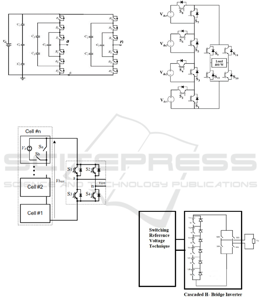
3.2.2 Diode-clamped multilevel inverter
(DCMLI)
The result of a multilevel inverter with diode
clamping is obtained by clamping voltages at multiple
levels using clamping diodes. This architecture has
the advantage of not requiring separate DC sources
and can be directly connected to DC-link voltage, but
it has the disadvantage of requiring more clamping
diodes [T. Porselvi, 2011].
Figure 4: Seven-level diode-clamped multilevel inverter.
3.2.3 Flying-Capacitor multilevel inverter
(FCMLI)
The operation process of a diode-clamped multilevel
inverter and a flying capacitor multilevel inverter is
the same, except that flying capacitors are used
instead of clamping diodes. The main disadvantage of
this architecture is that it necessitates higher capacitor
ratings.
Effective Multilevel Inverter with 129 Level Output
95
Clamping diodes' required voltage blocking
capability varies with level, which is one of the
drawbacks of employing diode-clamped multilevel
inverters [T. Porselvi, 2011].
Figure 5: Seven-level multilevel inverter with flying
capacitors arrangement.
3.2.4 Cascaded Sources Multilevel DC-Link
Inverter (CSMLDCLI)
Figure 6: Cascaded sources multilevel dc-link inverter
(CSMLDCLI).
The multilevel DC-link in this architecture can
alternatively be produced by a bypassing
uncontrolled device and a series inclusion switch for
each distinct DC source.
A cascaded half-bridge leg, a flying-capacitor
phase leg and a phase leg with a diode clamp can also
be used to create a multilevel dc link. Gui-Jai was the
first to propose these inverters in 2005 [Gui-Jia Su,
2002].
3.2.5 Multilevel DC-Link Inverter
(MLDCLI)
Figure 7: Cascaded sources multilevel DC-link inverter
(CSMLDCLI).
A multilevel DC-link (MLDCL) and a single H-
bridge inverter compose the power circuit in this
architecture. The MLDCL can be clamped by a diode,
a capacitor, or a cascaded half bridge phase leg. This
topology requires fewer components than the
preceding one [Ramkumar L Maurya, 2017].
4 PROPOSED MULTILEVEL
INVERTER TOPOLOGY
Figure 8: Circuit diagram of proposed 129 level multilevel
inverter.
The cascaded half- Bridge architecture was used in
the planned 129 level inverter. This topology
employs ten MOSEFETs and six clamping diodes.
ISPES 2023 - International Conference on Intelligent and Sustainable Power and Energy Systems
96
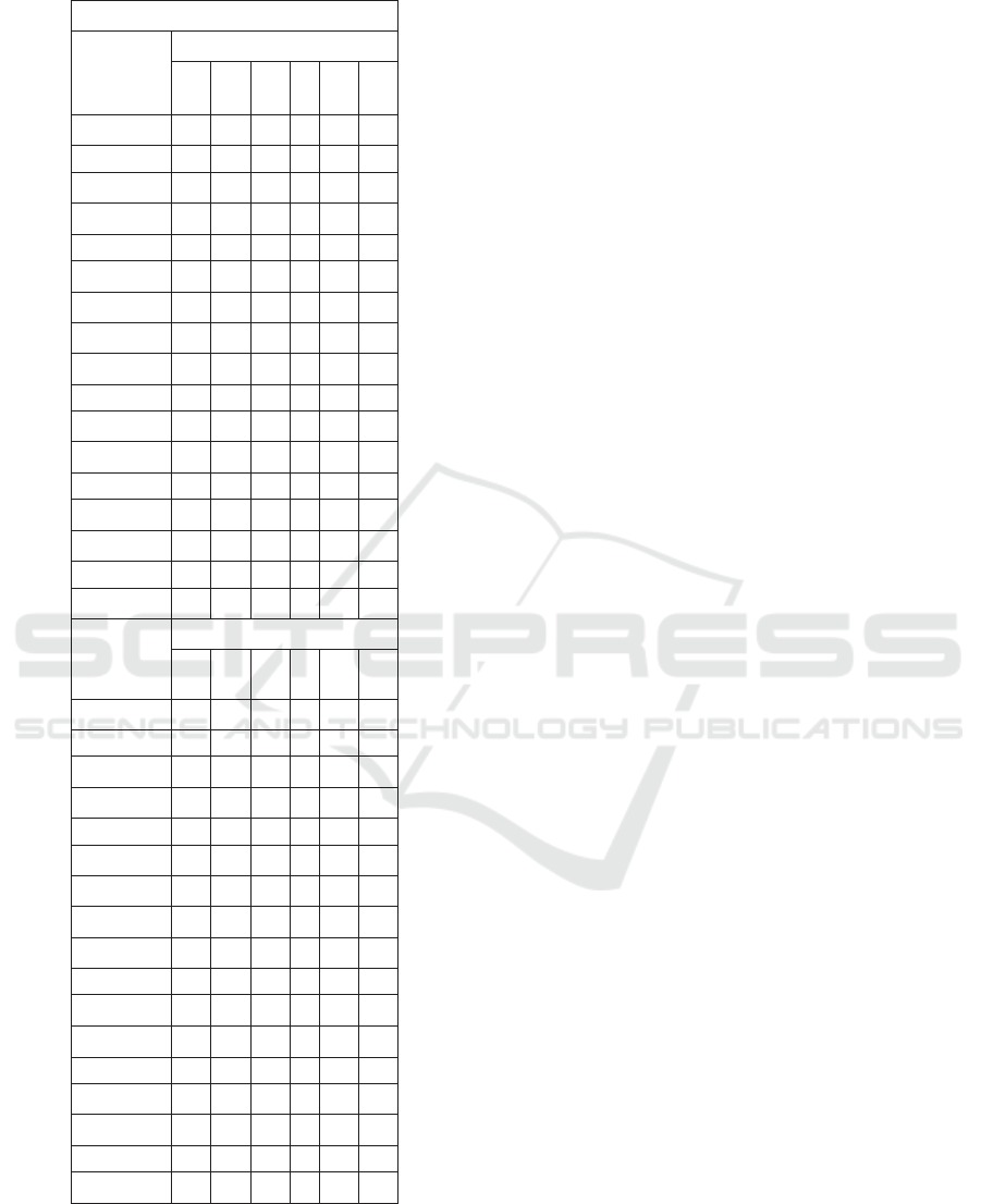
Table 1: Switching states.
Switching
States
Vo in
volts
Conducting Switches
S
1
S
2
S
3
S
4
S
5
S
6
+/- 64VDC
1
1
1
1
1
1
+/- 63VDC
0
1
1
1
1
1
+/- 62VDC
1
0
1
1
1
1
+/- 61VDC
0
0
1
1
1
1
+/- 60VDC
1
1
0
1
1
1
+/- 59VDC
0
1
0
1
1
1
+/- 58VDC
1
0
0
1
1
1
+/- 57VDC
0
0
0
1
1
1
+/- 56VDC
1
1
1
0
1
1
+/- 55VDC
0
1
1
0
1
1
+/- 54VDC
1
0
1
0
1
1
+/- 53VDC
0
0
1
0
1
1
+/- 52VDC
1
1
0
0
1
1
+/- 51VDC
0
1
0
0
1
1
+/- 50VDC
1
0
0
0
1
1
+/- 49VDC
0
0
0
0
1
1
+/- 48VDC
1
1
1
1
0
1
Vo in
volts
Conducting Diodes
D
1
D
2
D
3
D
4
D
5
D
6
+/- 64VDC
0
0
0
0
0
0
+/- 63VDC
1
0
0
0
0
0
+/- 62VDC
0
1
0
0
0
0
+/- 61VDC
1
1
0
0
0
0
+/- 60VDC
0
0
1
0
0
0
+/- 59VDC
1
0
1
0
0
0
+/- 58VDC
0
1
1
0
0
0
+/- 57VDC
1
1
1
0
0
0
+/- 56VDC
0
0
0
1
0
0
+/- 55VDC
1
0
0
1
0
0
+/- 54VDC
0
1
0
1
0
0
+/- 53VDC
1
1
0
1
0
0
+/- 52VDC
0
0
1
1
0
0
+/- 51VDC
1
0
1
1
0
0
+/- 50VDC
0
0
0
0
0
0
+/- 49VDC
1
0
0
0
0
0
+/- 48VDC
0
1
0
0
0
0
The first six MOSFETs are used to construct the
multilevel staircase output, and six clamping diodes
are employed to allow current to flow in just one
direction. The H- Bridge, which is made up of four
MOSFETs, is utilized to convert the staircase DC to
the staircase AC. In other words, the H-Bridge also
functions as a polarity switcher. The switching
signals are generated using the voltage reference
approach, and the pulses are delivered to the
MOSFETs. At the output of the H- Bridge, the
staircase AC voltage is obtained. To obtain a clean
output waveform, the LCL filter is used. In this
architecture, asymmetrical DC sources (i.e., six
distinct DC sources) are used.
The triggering positions of the MOSFET switches
for some of the states are shown in table 1. The ON
and OFF states of the S1–S6 switches are denoted by
1 or 0 respectively. Similarly, the diodes' conduction
and non-conduction states are represented by 1 or 0.
With the switch combinations shown in table 1, we
get +/- 64V and 0V, for a total of 129 voltage output
levels.
4.1 Asymmetrical Cascaded Multilevel
Topology
Asymmetric MLI designs provide a far more efficient
way of utilizing DC sources. In asymmetric setup,
non-equal DC sources V
dcn
are used instead of equal
ones. This allows for greater flexibility when
combining different V
dc
source values. As a result, it
generates higher output voltage levels with the same
amount of V
dcn
and switches as compared to
symmetric approaches in identical MLI arrangements
[Y. Suresh, 2017].
As a result, using asymmetrical DC sources has
the following advantages.
1. Asymmetrical DC voltage sources have voltages
that differ from one another.
2. The fundamental advantage of an asymmetrical
multilevel converter is that it utilizes fewer
semiconductor switches than symmetrical topology.
3. One attraction of asymmetrical arrangements is
that the number of levels is higher with the same
number of cells.
Here in this paper the seven asymmetrical DC sources
are used in 1:1:2:4:8:12:16 ratio. These different
voltage combinations make the 129 level output as
sinewave.
5 SIMULATION RESULTS
MATLAB/ SIMULINK is a very good platform for
circuit design. So the simulation of the circuit is done
by this MATLAB/ SIMULINK software 2019a.
Effective Multilevel Inverter with 129 Level Output
97

Figure 9: Circuit Diagram of proposed inverter.
The topology constructed anew is simulated in
MATALB/ SIMULINK software and the results are
exhibited here. Figure 9 shows the simulation circuit
diagram developed in MATLAB/ SIMULINK.
Figures 10, 11 show the output voltage and output
current of the proposed 129 level inverter. The figure
12 shows the lower THD of the new 129 level
inverter. The proposed inverter's voltage output and
current output are therefore sinewaves.
Figure 10: Output Voltage (Vo) for R Load.
Figure 11: Output Current (Io) for R Load.
Figure 12: THD of proposed inverter.
6 CONCLUSIONS
The innovative MLI topology described in this paper
is based on a standard asymmetric cascaded inverter.
Asymmetric DC sources are used to increase the
number of output voltage levels with lower devices.
The H- Bridge acts as a polarity changer and produce
positive and negative polarity of the output voltage.
In an asymmetrical configuration, the given
architecture provides one twenty-nine level output
with only ten switches. As a result, switching losses
are reduced and the cost of the devices is reduced. The
output waveform is a sinewave. The percentage THD
level is 0.69. The method was successfully
constructed and tested using the MATLAB/Simulink
R2019a software.
REFERENCES
J. Rodríguez, J.-S. Lai, and F. Z. Peng. (2002). Multilevel
inverters: A survey of topologies, controls and
applications, IEEE Trans. Ind. Electron. vol. 49, no. 4,
pp. 724–738.
K.T. Maheswari, R. Bharanikumar, V. Arjun, R. Amrish,
M. Bhuvanesh. (2021). A comprehensive review on
cascaded H-bridge multilevel inverter for medium
voltage high power applications, Materials Today:
Proceedings, Volume 45, Part 2, Pages 2666-2670.
Keith Corzine, Yakov Familiant. (2002). A New Cascaded
Multilevel H-Bridge Drive, IEEE Transactions on
Power Electronics, VOL. 17, NO. 1.
P. Omer, J. Kumar and B. S. Surjan. (2020). A Review on
Reduced Switch Count Multilevel Inverter Topologies,
in IEEE Access, vol. 8, pp. 22281-22302, doi:
10.1109/Access.2020.2969551.
A. Ali and J. Nakka. (2016). Improved performance of
cascaded multilevel inverter, in Proc. Int. Conf.
Microelectron., Comput. Commun. (Micro Com), pp.
1–5.
ISPES 2023 - International Conference on Intelligent and Sustainable Power and Energy Systems
98

Ronak A. Rana, Sujal A. Patel, Anand Muthusamy, Chee
woo Lee, and Hee-Je Kim. (2019). Review of
Multilevel Voltage Source Inverter Topologies and
Analysis of Harmonics Distortions in FC-MLI,
Electronics, 8, 1329; doi: 10.3390/electronics8111329
T. Porselvi and R. Muthu. (2011). Comparison of cascaded
H-Bridge, neutral point clamped and flying capacitor
multilevel inverters using multicarrier PWM, in Proc.
Annu. IEEE India Conf., pp. 1–4.
Gui-Jia Su and Donald J. Adams. (2002). Oak Ridge
National Laboratory, Oak Ridge, TN, U.S.A.,
Multilevel DC Link Inverters, Submitted to the IEEE
IAS 2002 Annual meeting, DE-AC05-00OR22725.
Ramkumar L Maurya, Fr. C. (2017). Rodrigues Institute of
Technology, Mini Rajeev, Implementation of
Multilevel DC-Link Inverter for Standalone
Application, International Conference on Nascent
Technologies in the Engineering Field (ICNTE-2017),
978-1-5090-2794-1/17/$31.00 ©2017 IEEE.
Y. Suresh, J. Venkataramanaiah, A. K. Panda, C.
Dhanamjayulu, and P.Venugopal. (2017). Investigation
on cascade multilevel inverter with symmetric,
asymmetric, hybrid and multi-cell configurations, Ain
Shams Eng. J., vol. 8, no. 2, pp. 263–276.
Keith Corzine, Yakov Familiant. (2002). A New Cascaded
Multilevel H-Bridge Drive, IEEE Transactions on
Power Electronics, VOL. 17, NO. 1.
Effective Multilevel Inverter with 129 Level Output
99
