
MOTION PLANNING APPROACH OF A MULTI-FINGERED
ROBOT FOR CARTON FOLDING OPERATIONS
Hidetsugu Terada, Takayuki Kobayashi
Graduate School of Medical and Engineering,Department of Mechanical System Engineering, University of Yamanashi
Takeda4-3-11,Kofu, Yamanashi, 4008511, JAPAN
Keywords: Robot, Multi, Finger, Carton, Folding, Motion, Planning
Abstract: The motion planning approach of a multi-fingered robot for carton flap folding operations has been newly
develop
ed. This approach considers the loci of the tool center point for carton flap folding operations. Also
that considers the pushing or fixing points of the carton flap. This approach is calculated from the rotating
angle for carton flap folding and the position of a robot finger tip in contact with the carton surface, using
inverse kinematics. And this approach can be adapted to changes of a carton size or a folding position. In
cases in which the carton flap is folded using this approach, the robot finger tip touches the carton surface
without slipping and moves along circular continuous path. Therefore in case of the rectangular carton box
folding, each robot finger moves in each 2.5-dimensional Cartesian frame. In this report, the proposed
approach is verified using a prototype robot system. This prototype system consists of two pairs of the robot
fingers and rotating mechanism for carton paper. Each finger has a 3-DOF SCARA type robot and a 1-DOF
linear motion system. The testing carton boxes can be folded to the desired shape.
1 INTRODUCTION
An industrial robot for assembling is used in various
fields, for example mechanical or electrical parts
assembling and circuit board testing. Especially, in
recent years, the industrial robots are used to handle
soft products like a cloth or a paper (Buckingham,
1996). However, for the assembling of carton box
which is the one of the soft products operations, the
use of robot system is not yet popular.
The carton box is usually assembled with
ben
ding some carton flaps and lid, as shown in
Figure 1. The carton box is assembled with bending
on the various positions and to various directions,
even like this simple rectangular shape. So in
general, a carton is assembled using the special
assembling machine (Kyoto-seisakusho, 2004).
Also, the packaging carton is often desired the
complex shape or folding procedure based on
industrial or artistic design. Therefore, it is difficult
to adapt the various kinds of the carton using the
conventional assembling machine. So, the robot
system with higher dexterity is needed.
For carton box assembling, the robot system
wi
th higher dexterity can be adapted to the various
changes of carton size, shape or carton folding
procedure. In other words, the many parameters of
robot control have to be decided for the motion
planning. These parameters are the folding or fixing
positions, the folding angles with directions and the
order of folding operations. Although it is difficult to
teach the carton box assembling procedure using
conventional robot system, that procedure has to be
taught directly, using the "Direct teaching method"
(Rosheim, 1994). When that parameter which is the
position or the order of folding is changed using that
conventional method, it is necessary to teach all
motion again. So the conventional method is not
useful. Also, some researches have shown the
quantification method of a carton assembling
procedure (Song, 2001, and Dubey, 2003). In that
method, the robot motion locus was not considered
with a folding procedure. So the robot motion
control method had to be generated, using other
procedure.
In this report, the simplified motion planning
approach, which realizes
the quantification of carton
box assembling operations, is newly proposed. And
the locus of robot motion is considered to this
approach. And the structure of robot system and the
353
Terada H. and Kobayashi T. (2004).
MOTION PLANNING APPROACH OF A MULTI-FINGERED ROBOT FOR CARTON FOLDING OPERATIONS.
In Proceedings of the First International Conference on Informatics in Control, Automation and Robotics, pages 353-360
DOI: 10.5220/0001126203530360
Copyright
c
SciTePress
robot motion loci are investigated. Then, the
prototype robot system, which consists of two pairs
of the robot fingers and the rotating mechanism of
carton paper, is tested. Each finger has a SCARA
type robot and a linear motion system. And the test
carton boxes are folded to verify the validity of that
proposed approach and the robot system.
2 MOTION PLANNING FOR
CARTON FOLDING
OPERATIONS
In general, a carton paper for the packaging box is
made from a hard paper, which has similar plastic
deformation characteristics like an aluminium
bending. Also, it is different from a soft paper like a
newspaper. In addition, the outline of that carton
paper is usually blanked using cutting machine. And
that is usually embossed with folding-lines. Then,
the conventional special assembling machine
assembles the carton paper which is fixed on the
base plate using a vacuum-Chuck or a fixture. In this
research, it is assumed that these conditions are
applied to investigate the quantification of
assembling carton box using the robot system.
When we assemble a carton box by folding, we
often push the flap using our fingers which slip on
that flap. However, the influences of a friction
fluctuate by the environment and paper material etc..
In industrial fields for carton box assembling, we
should eliminate an influence of that friction. Also
the conventional special assembling machine can
fold the carton paper without slipping. So it is
assumed that the robot finger moves without
slipping, too.
A motion of the carton flap folding on the
arbitrary position and pose is defined using the polar
vector analysis (Makino, 1998) as shown in Figure 2.
That folding motion is replaced to the rotational
motion around the arbitrary axis. And that motion
includes the translational motion from origin point.
Also for this operation, it is assumed that the carton
flap is folded with pushing on the single point. The
quantification of a carton paper folding operation
which considers these assumptions is investigated.
At first, the initial orientation frame of a carton
paper is converted using arbitrary axis rotation E
-
ω
0
θ
0
.
In that figure, the rotating axis of a flap folding is
rotated to the j-axis on the Cartesian frame. And the
folding motion is replaced to the rotating motion of
the center of gravity (CGr) of each flap. Each CGr
on flap is calculated from each area. In that figure,
each CGr is defined as the polar vector C
i
0
and C
i
1
from the origin point O
p
. The CGr on a flap is
defined as the tool center point (TCP) of a folding
operation. In that figure, the pushing point conforms
to the C
i
1
. Then the distances between the CGr and
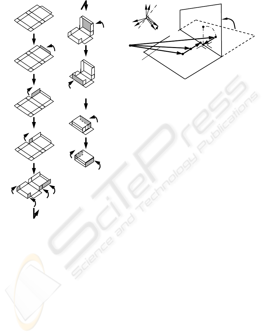
Figure 1: Example of an assembling procedure for
rectangular carton box
Lid Folding
Flap Folding
Flap Folding
Flap Folding
Each flap folding
Flap Folding
Flap Folding
Flap Folding
Flap Folding
Lid Folding
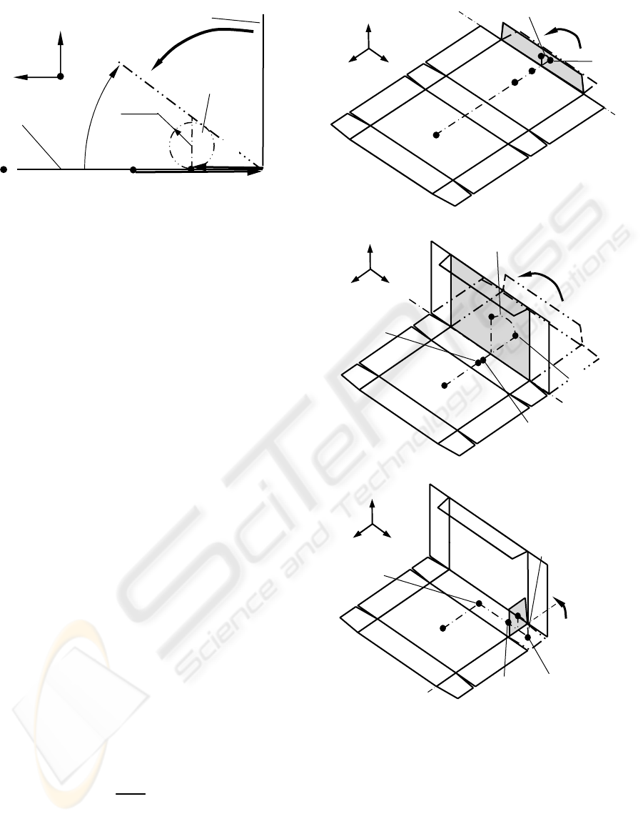
Figure 2: Geometry of a carton flap folding
O
p
1
θ
j
E
i
0
C
i
1
C
i
0
A
i
1
A
i
0
F
Folding
w
k
u
i
v
j
θ
0
ω
0
ICINCO 2004 - ROBOTICS AND AUTOMATION
354
9
θ
j
E
i
8
C
i
9
C
the folding-line are defined as
A
i
0
and A
i
1
. So the
folding operation is shown as follows:
(
)
i
j
ii
1111
1
00
AEACEP
θ
θω
−+=
−
(1)
In case of a rectangular carton box assembling,
each folding axis conforms to the principal axis of
the Cartesian frame. And the end point of
A
i
0
conforms to the end point of
A
i
1
. And each distance
is same. So, the folding operation is simplified as
follows:
i
j
ii
1111
1
AEACP
θ
−+=
(2)
In cases in which the carton paper is folded
without slipping, the fixing point for carton flap
folding should be near the folding axis line as shown
in Figure 3. And when the carton paper is folded
along the embossed folding-line, the fixing point and
the push point need to be symmetrical with respect
to the folding-line, in general. And the fixing point
holds a constant point during a folding operation.
Also, these points are operated simultaneously. In
other words, the two fingers need to co-operate to
fold a carton flap.
In general, the carton flap is often folded over 90
degrees. When the robot fingers which are just like a
human finger are used, the collision avoidance
between the carton flap and the carton fixing robot
finger has to be considered. So, it is assumed that the
robot end-effector has a ball shape to simplify that
procedure. This imaginary radius is defined as r.
And
τ
is the supplemental angle of the flap folding
as shown in Figure 3. And the fixing point is defined
as follows:
(
)
iiii
00000
0000
BACEFEF −+==
−−
θωθω
(3)
T
i
r
⎟
⎠
⎞
⎜
⎝
⎛
= 0,0,
tan
0
τ
B (4)
There are two procedures to approach this fixing
point. To avoid the collision, each robot finger is
approached from the same side as an initial finger
position with respect to the carton paper. In case of
the example which shows in Figure 3, the robot
finger for fixing approaches from left side. And the
robot finger for folding approaches from right side.
However, in case of the carton lid folding, the carton
paper is folded over itself. There is the possibility
that the collision between robot finger and carton lid
will occur. In this case, the carton paper is fixed
using a fixture or a vacuum-Chuck, instead of a
fixing finger. This fixture is similar to the
conventional special assembling machine. Using
Flap folding
i
8
F
O
p
i
j
k
i
0
C
i
7
C
i
8
C
8
θ
j
E
Lid folding
i
7
F
O
p
Figure 4: Geometry of a fixed point on carton flap
(a) Flap folding
(b) Carton lid folding
i
j
k
(c) Side flap folding
i
7
C
j
10
C
10
θ
i
E
Side flap
folding
j
10
F
O
p
i
j
k
Folding
p
O
i
0
A
i
0
B
i
0
F
Imaginary ball
Flap
Fixed carton
τ
j
i
k
r
Figure 3: Geometry of a fixing point on carton flap
MOTION PLANNING APPROACH OF A MULTI-FINGERED ROBOT FOR CARTON FOLDING OPERATIONS
355
these definitions and conditions, all folding motions
can be quantified.
Figure 4 shows the example of a carton flap
folding, that carton box has a rectangular shape. The
CGr of each flap is defined as
C
m
n
. And the carton
fixing point using robot finger is defined as
F
m
n
. And
for the flap folding, the rotation of each CGr on a,
flap is defined as the rotation matrix
E
m
θ
n
. Also the
distance between CGr and folding-line is defined as
the vector
A
m
n
. It is assumed that fixing point using
vacuum-Chuck conforms to the origin point of a
carton paper. The m shows the axis direction on the
Cartesian frame, and the n shows the number of flap.
In case of a flap folding around the j-axis at 90
degrees as shown in Figure 4(a), the folding motion
is defined as follows:
i
j
ii
9991
9
AEACP
θ
−+=
(5)
And the fixing point is defined as the constant vector
F
i
8
. And in case of a carton lid folding around the j-
axis at 90degrees as shown in Figure 4(b), the
folding motion is defined as follows:
i
j
ii
8882
8
AEACP
θ
−+=
(6)
The fixing point is defined as the constant vector
F
i
7
.
Also, in case of a side flap folding around the i-axis
at 90degrees as shown in Figure 4(c), the folding
motion is defined as follows:
j
i
jj
1010103
10
AEACP
θ
−+=
(7)
In this case, the fixing point is shifted to the j-axis
direction from
C
i
7
. So the fixing point is defined as
the constant vector
C
i
7
+F
j
10
.
These vector equations show the folding motions
and the operating procedure of carton assembling
conforms to the execution order of these equations.
It can be adapted to the change required by replacing
the order of those equations. In other words, the
motion planning approach of a carton assembling
can be quantified using some equations and the
order of those equations.
3 FINGER MOTION LOCI FOR
CARTON FOLDING
The motion planning approach for carton box
assembling has been proposed using a newly
developed quantification approach of carton flap
folding. Next, the loci of robot fingers are
investigated using this approach.
The point touched with the TCP of robot finger
rotates around the folding-line at the required angle.
This motion locus has a circular locus, in any
folding operations. And all motions of a robot finger
are regarded as the planar motion. This plane is
defined as "Folding-plane". Especially for
rectangular carton box assembling, the Folding-
plane is moved linearly to include each TCP’s locus,
as shown in Figure 5. And in case that the carton
flap folds around the arbitrary folding-line, that
plane can conform to the motion locus by translating
along some axes and by rotating around some axes.
Then, the carton box is assembled by robot finger,
the influence of a finger slip on a carton paper needs
to eliminate as much as possible. So, the robot finger
maintains the perpendicular pose to the carton flap
during the folding operation. And the robot finger
needs to avoid a collision at the other section of a
carton paper. So it is the most simplified and useful
approach to conform the pose of a robot finger tip
and the tangent direction of a motion locus.
For the assembling of rectangular carton box as
shown in Figure 1, the degree of freedom (DOF) of a
robot finger needs the 2-DOF of the position and the
1-DOF of the pose on a Folding-plane. And the
Folding-plane needs to include the motion locus. So
the translation and the rotation mechanism on a
robot base section are needed. However when that
robot system consists of the robot finger without the
rotating mechanism, that robot system needs two
pairs of robot fingers to realize the same carton
folding operation. These pairs should be assigned on
the perpendicular location.
On the other hand, a robot finger fixes a carton
paper to avoid the releasing of the carton paper from
fixed base which is caused by the elastic
deformation of that paper, during that paper fixed
operation. A robot finger should avoid the collision
with other sections of carton paper during that
operation. So, the pose of the robot finger which
fixes a carton paper needs to consider a folding
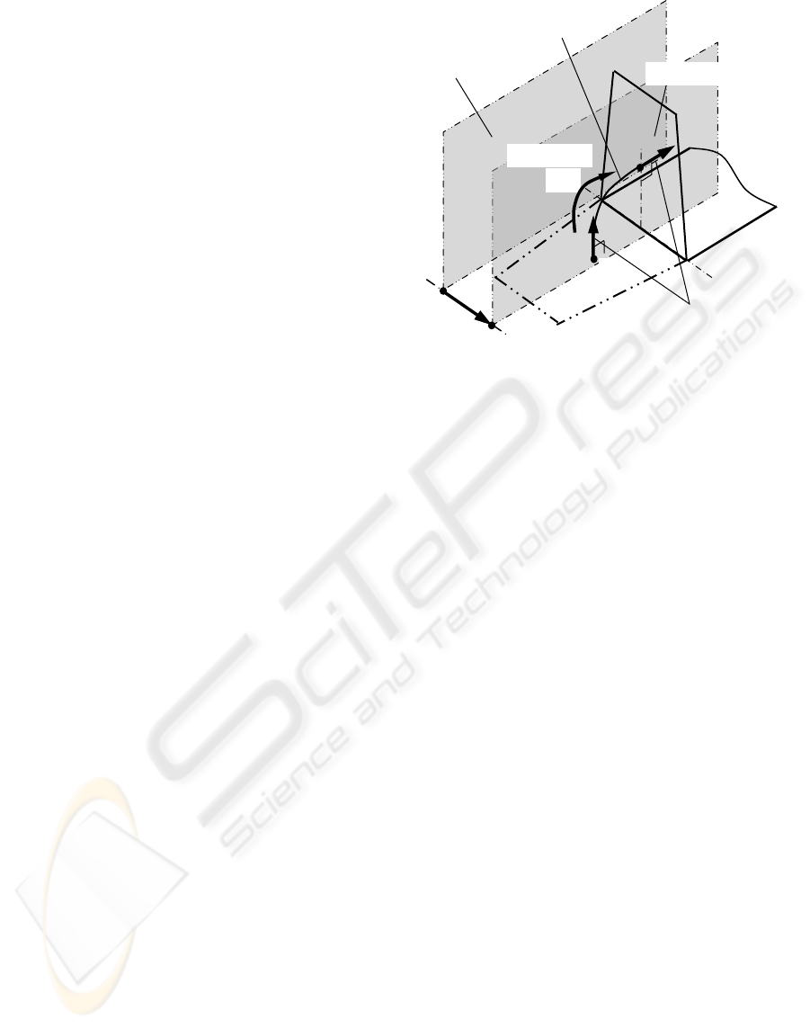
Robot finger motion
direction
1
θ
j
E
i
1
C
Flap folding
Folding axis
Folding-plane
Carton flap
TCP motion circular locus
O
p
O
p
’
Figure 5: Geometry of a tool center point (TCP)
motion and a "Folding-plane"
ICINCO 2004 - ROBOTICS AND AUTOMATION
356
angle. In cases in which the robot finger folds the
carton flap at 90 degrees, as shown in Figure 5, the
robot finger with vertical pose of that finger tip can
fix that carton paper.
However, the carton paper usually has the
"Spring-Back" characteristic which is just like
stainless-steel. So, the supplemental angle for the
flap folding is defined as the 45-90degrees. And the
robot end-effector has a ball shape. So, this
condition and Equation (4) should be considered to
the pose of the robot finger which fixes the carton
paper. Also, to adapt to the various folding
operations each robot finger has a same finger
structure. And they are installed to make face to face
location. Then, they are symmetrical with respect to
the carton paper or working-area. And the Folding-
plane of a folding motion conforms to that plane of a
fixing motion. Both translational mechanisms move
simultaneously.
4 KINEMATICS OF A ROBOT
FINGER
Considering the proposed motion planning approach,
and the robot finger motion on that Folding-plane,
the robot finger consists of a 3-DOF serial link and a
translational mechanism. On that Folding-plane, the
SCARA robot folds a carton flap as shown in Figure
6. That robot finger has the simplest structure that is
the minimum DOF. The position
P and pose E of a
robot finger are defined using the polar vector
analysis shown as Equation 8 and 9.
(
((
iji
j
i
j
i
j
kj
4321
00
321
BECECECE
CLP
α
θ
θθ
++++
+=
)
))
(8)
α
θθθ
j
jjj
EEEEE
321
=
(9)
Each linkage length is defined as
C
k
0
, C
i
1
, C
i
2
and
C
i
3
. Also each robot joint rotation is defined as E
j
θ
1
,
E
j
θ
2
and E
j
θ
3
. The origin point Op conforms to the
start point of the translational motion
L
j
0
. The robot
finger tip has a spherical shape. When that robot
finger folds a carton flap, the contact point is on the
extended vector of the
C
i
3
. And in cases in which the
robot finger fixes a carton paper, this finger tip has
an inclined pose at
τ
’. In other words, the contact
point on each finger tip is different. So the contact
point from a finger center is defined as
E
j
α
B
i
4
. Also
the spherical shape radius of a robot finger is defined
as
B
i
4
. In case of a folding operation, the contact
point is on the extended vector of the
C
i
3
, it is
α
=0.
And in case of a carton fixed operation, that is
α
=
τ
'.
The folding operation is independent of the
translational operation for the Folding-plane. So, the
kinematics of that robot system can be regarded as
the two individual analyses; the one is the robot
finger section and the other is the translational
mechanism section. For the forward and inverse
kinematics of the robot finger as shown Figure 6, the
3-DOF type SCARA robot and the 1-DOF linear
motion mechanism are analyzed. In general, the
SCARA robot has two solutions which are the
"Right hand solution" and the "Left hand solution"
(Furuya et al., 1983). The robot finger for the carton
fixing operation usually uses the opposite solution to
that folding operation. And the solution doesn’t
change during the folding or fixing operation.
In cases in which the carton flap folds on the
arbitrary position and the pose, the carton paper
rotates to conform that folding-line to the motion
direction of that translational mechanism; the
position and pose shown as Equation 8 and 9, rotate
around the arbitrary axis. In case that carton paper is
rotated around k-axis of the Cartesian frame that is
popular for carton folding, the position and posture
of a robot finger are changed to the
P' and E', shown
as Equation 10 and 11.
PEP
λ
k
=
′
(10)
EEE
λ
k
=
′
(11)
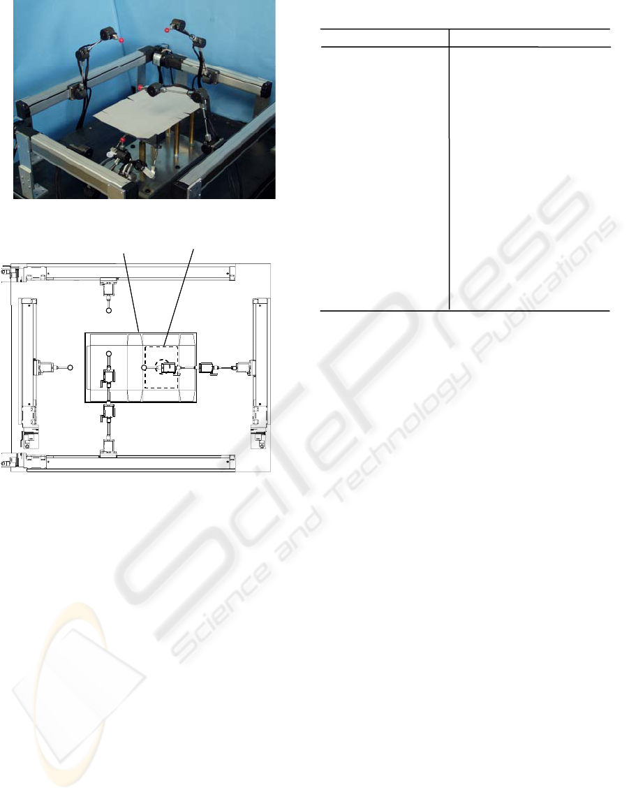
5 PROTOTYPE ROBOT SYSTEM
Considering the proposed motion planning approach
for carton box assembling and the circular motion
for robot fingers, the prototype of a robot system has
been made. That system consists of two pairs of the
3-DOF SCARA robot fingers with the 1-DOF
translational motion mechanism and rotating
mechanism of carton paper, as shown in Figure 7(a).
Each robot finger moves simultaneously in a single
working area as shown in Figure 7(b). Each finger is
installed to make face to face location. And each
i
1
C
1
θ
j
E
k
0
C
j
0
L
i
2
C
i
3
C
2
θ
j
E
3
θ
j
E
ija
4
BE
Folding plane
Contact point
O
p
i
j
k
Figure 6: Vectors geometry of a robot finger
MOTION PLANNING APPROACH OF A MULTI-FINGERED ROBOT FOR CARTON FOLDING OPERATIONS
357
pair of that finger is placed to make perpendicular
location. Also, each pair of translational motion
mechanism which is installed to make parallel
location moves simultaneously, too. The rotating
mechanism around k-axis on Cartesian frame with
the vacuum-Chuck which fixes a carton paper on
carton base section is installed under that working
area. Therefore, we can test two approaches using
this prototype system. The one is the approach of
two pairs of robot fingers, and another is the
approach of a pair of robot fingers with a rotating
mechanism.
Each finger has small and light-weight joint
actuators which consist of an AC servo-motor,
encoder and Harmonic-drive reducer (Umetsu
et.al.1993). And that size is 30mm diameter with
length 30mm and the weight is the 70gf. That
actuator uses to the rotating mechanism for carton
paper, too. Then, each link of a robot finger has a
cylindrical shape made from steel to minimize a
collision at the other section of carton paper. That
diameter is the 4mm; it is smaller than the joint
diameter. Also, the finger tip has a ball shape which
is made from the Butadiene rubber to eliminate the
slipping on a carton paper. That diameter is the
6.5mm. And also the translational mechanism
consists of a ball screw with an AC servo-motor and
a linear guide slide system (THK, 2004). The
specifications of these actuators are shown in Table
1. Furthermore, all axes of the robot system are
controlled synchronously by the command PC. That
control data are communicated using a parallel
communication protocol.
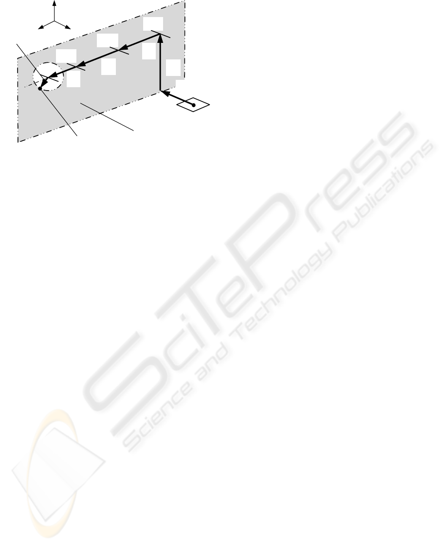
Working area
(300mm× 200mm)
Robot 0
Robot 1
Robot 2
Robot 3
Carton fixture with paper
rotation mechanism
Working area
(300mm× 200mm)
Robot 0
Robot 1
Robot 2
Robot 3
Carton fixture with paper
rotation mechanism
6 VERIFICATION USING THE
PROTOTYPE ROBOT SYSTEM
The rectangular carton box as shown in Figure 1 has
been assembled to verify the usefulness for proposed
motion planning approach and robot motion. It is
proved that the folding procedures for carton flaps
can be quantified. And the robot fingers, the
translational mechanisms and the rotating
mechanism can move simultaneously, which are
based on the proposed approach. Also, it is proved
that the carton box can be assembled.
In case of the rectangular carton box has twelve
folding operations, the mean Cycle time for carton
folding is 10.5 seconds. It is because that maximum
speed of a robot finger actuator is limited to 22.5rpm.
When it is required that robot finger moves more
quickly, the actuator of that robot finger should be
improved to adapt to higher rotation. Figure 8(a)
shows the relations of each robot finger joint angle
with the sample motion for the carton flap folding at
Figure 7: The multi-fingered robot system with carton
paper rotating mechanism
(b) Robot assignment and working area
(a) Structure
Items Values
Robot finger type 3-DOF SCARA type
Finger 1st and 2nd link 130mm
Finger 3rd link 50mm
Finger actuator Hybrid motor-reducer type
Max. speed 22.5rpm
Motor AC servo-motor, 1.4W
Encoder 128p/r
Reducer i: 1/80, Harmonic Drive
Tool head diameter 6.5mm
Tool head material Butadiene rubber
Rotating mechanism k-axis rotating
Linear actuator Ball screw type, lead 8.0mm
Max. speed 600mm/s
Motor AC servo motor, 30W
Encoder 2000p/r
Stroke Robot0, 2: 400mm,
Robot1,
3: 200mm
Table 1: Specifications of a prototype robot system
ICINCO 2004 - ROBOTICS AND AUTOMATION
358
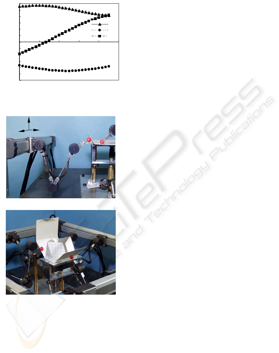
60 degrees. Each joint angle of a robot finger for
folding operation is shown in Figure 8(b).
Considering the "Spring-back" characteristic, that
carton paper is folded to 135 degrees. Also this
proposed motion planning approach using robot
system doesn’t need a force control of a carton
folding. It is similar to the conventional special
assembling machine.
Then, this robot system based on proposed
approach, can deal with the complex shape of the
carton box like “Boy-scouts tent” in which the
conventional special assembling machine cannot be
adapted as shown in Figure 8(c). And using
proposed approach, the robot motion can be taught
by off-line. It isn't necessary to move each robot
finger to teach like a conventional robot system. It is
very useful to reducing the set-up time.
In future work, to realize the other operation for
carton packaging, we will investigate the grasping
procedure of papers or products with force control.
7 CONCLUSIONS
For carton box assembling, the carton flap folding
procedure which is quantified to simplify the motion
planning approach has been newly proposed. This
procedure considers the loci of the center of gravity
of carton flaps and the robot motion. Using the
multi-fingered prototype robot system, we have
verified the proposed approach; it is proved that the
folding procedures of the carton flaps can be
quantified. Also the carton box can be assembled.
For the sample assembling rectangular carton box,
the mean "Tact-time" for a carton flap folding is the
10.5 seconds.
In future work, to realize the work-handling of
the carton packaging that is different from the carton
flap folding, we will develop the approach of
grasping with a force control.
REFERENCES
Buckingham R., 1996, Multi-arm Robots, Industrial Robot,
vol.23, No.1.
http://www.kyotoss.co.jp/, 2004.
Rosheim M., 1994, Robot Evolution, John Wiley & Sons.
Song G. and Amato N., 2001, A Motion Planning
Approach to Folding: Form Paper Craft to Protein
Folding, Proceedings of the 2001 IEEE International
Conference on Robotics and Automation, 948.
Dubey V. and Crowder R., 2003, Designing a Dexterous
Re-configurable Packaging System for Flexible
Automation, Proceedings of the 2003 ASME Design
Engineering Technical Conferences and Computers
and Information in Engineering Conference.
Makino H. 1998, 3-dimensional Kinematics, Nikkankogyo
Sinbunsha.
Furuya N. and Makino H., 1983, Calibration of SCARA
Robot Dimensions Teaching, Journal of the Japan
Society for Precision Engineering, vol.49, No.9.
(b) Robot finger motion at the folding angle 60 degrees
Figure 8: The test motion of a carton flap folding
(a) Relation between the folding angle and each robo
t
finger joint angle to 135degrees
i
k
j
-180
-150
-120
-90
-60
-30
0
30
60
90
120
150
180
0 30 60 90 120 150
Folding angle deg
Robot joint rotating angle deg
θ1
θ2
θ3
(c) Folding motion for “Boy-scouts tent” type carton box
MOTION PLANNING APPROACH OF A MULTI-FINGERED ROBOT FOR CARTON FOLDING OPERATIONS
359

Umetsu M. and Oniki K., 1993, Compliant Control of
Arm-Hand System, Proceedings of the 1993 JSME
International Conference on Advanced Mechatronics.
http://www.thk.co.jp/, 2004.
ICINCO 2004 - ROBOTICS AND AUTOMATION
360
