
DEVICE INTEGRATION INTO AUTOMATION SYSTEMS WITH
CONFIGURABLE DEVICE HANDLER
Anton Scheibelmasser, Udo Traussnigg
Department of Automation Technology,CAMPUS 02, Körblergasse 111, Graz, Austria
Georg Schindin, Ivo Derado
Test Bed Automation and Control Systems, AVL List GmbH, Hans List Platz 1, Graz, Austria
Keywords: Measurement device, automation system, Configurable Device Handler, test bed
Abstract: One of the most important topics in the field of autom
ation systems is the integration of sensors, actuators,
measurement devices and automation subsystems. Especially automation systems like test beds in the
automotive industry impose high requirements regarding flexibility and reduced setup and integration time
for new devices and operating modes. The core function of any automation system is the acquisition,
evaluation and control of data received by sensors and sent to actuators. Sensors and actuators can be
connected directly to the automation systems. In this case they are parameterised using specific software
components, which determine the characteristics of every channel. In contrast to this, smart sensors,
measurement devices or complex subsystems have to be integrated by means of different physical
communication lines and protocols. The challenge for the automation system is to provide an integration
platform, which will offer easy and flexible way for the integration of this type of devices. On the one hand,
a sophisticated interface to the automation system should trigger, synchronise and evaluate values of
different devices. On the other hand, a simple user interface for device integration should facilitate the
flexible and straightforward device integration procedure for the customer. Configurable Device Handler is
a software layer in the automation system, which offers a best trade-off between the complex functionality
of intelligent devices and their integration in a simple, fast and flexible way. Due to a straightforward
integration procedure, it is possible to integrate new devices and operation modes in a minimum of time by
focusing on device functions and configuring the automation system, rather than writing software for
specific device subsystems. This article gives an overview of Configurable Device Handler, which was
implemented in the test bed automation system PUMA Open developed at the AVL. It provides an insight
into the architecture of the Configurable Device Handler and shows the principles and the ideas behind it.
Finally, new aspects and future developments are discussed.
1 INTRODUCTION
The general task of an automation system is to
control a system in a defined mode of operation. In
order for the automation system to perform this task,
a number of sensors and actuators have to be
evaluated and controlled. Since the timing of the
automation system is critical, its software has to
establish real time data acquisition and control. A
further requirement is to evaluate and calculate
results based on the acquired data and to store them.
Particularly, automation systems used in the field of
CAT (Computer Aided Testing, e.g. combustion
engine development), called test beds, have to store
the acquired data during the test run into a database,
so that the developer can calculate specific quantities
for quality assurance or optimisation. Systems under
test are monitored and controlled by various devices
connected to the automation systems.
Concerning the complexity of the data
acq
uisition and control, devices can be divided into
two categories. The first category of devices can be
described as simple actuators (e.g. valves) or sensors
(e.g. temperature sensor Pt100), which are connected
to an input/output system as part of the automation
198
Scheibelmasser A., Traussnigg U., Schindin G. and Derado I. (2004).
DEVICE INTEGRATION INTO AUTOMATION SYSTEMS WITH CONFIGURABLE DEVICE HANDLER.
In Proceedings of the First International Conference on Informatics in Control, Automation and Robotics, pages 198-205
DOI: 10.5220/0001126501980205
Copyright
c
SciTePress
system. Since the sensors and actuators are under the
control of the real time system, they are usually
completely integrated into the automation system.
Depending on the use of the sensor/actuator, specific
parameterisation (e.g. acquisition rate, filtering or
buffering) has to be performed by the customer.
The second category could be described as
intelligent subsystems (e.g. measurement devices).
In contrast to the first category, they are controlled
by a local microprocessor, which provides functions
comparable to those of the automation system (e.g.
real time data acquisition or statistical calculation).
Devices of this group could be qualified as finite
automata with several internal states and transitions.
Usually they are connected to the automation system
via physical line (e.g. RS232, Ethernet).
Consequently, data acquisition and control is
possible only via this physical line and by using
diverse communication protocols on it.
These various types of devices have to be
uniformly integrated into the automation system, so
that data acquisition and device control can be
performed in a common way. Thus, automation
systems typically contain a software layer, with the
main task to make device specific functions
available via standard automation interfaces. We
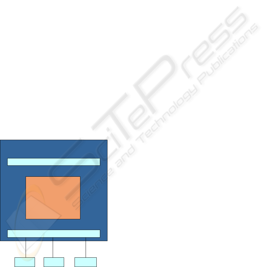
refer to this software layer as Device Handler (see
figure 1). Specifically, there are two main
automation interfaces in PUMA Open (AVL, 2004),
which are used by Device Handler, i.e., Platform
Adapter and Device Framework.
Figure 1: Device Handler
The former interface offers functions compatible
to those of the ASAM-GDI Platform Adapter
(ASAM, 2001). There are two main advantages of
the Platform Adapter. Firstly, it abstracts the
complexity of lower ISO/OSI layers 1-6 (ISO, 1990)
and it provides to the client a generic interface where
common read/write commands from/to the device
are independent from the specific lower ISO/OSI
layers (TCP/IP over Ethernet, RS232, CAN, etc.).
Secondly, it provides standard OS-services (e.g.
memory handling and synchronisation) and thus
enables the client to be independent from the
specific OS. Consequently, the client, i.e. the Device
Handler, deals exclusively with device specific
functions and it is therefore robust to changes of
lower communication layers and/or OS’s.
The later interface must be implemented by the
Device Handler and it contains services that are to
be used by the automation system, i.e., user. This
comprises services, such as: handling of device
channels (System Channels), device
parameterisation, support of the standard Device
Handler’s state machine, data storage, etc.
2 DEVICE HANDLER TYPES
One of the most important aspects of the automation
system is the synchronisation of all test bed
components (software and hardware) in order to
perform specific control and/or measurement tasks
(e.g. power-up all devices or get ready to start the
measurement of the system under test). As
mentioned in the previous chapter, all devices are
synchronised due to the fact that all Device Handlers
behave in a uniform way, which is ensured by
supporting the state machine, i.e., states and
transitions of the Device Framework interface. For
instance, if the automation system wants to perform
a measurement, it simply invokes the transition
StartMeasurement of each Device Handler. The
Device Handler interprets this command in a device
specific way and accordingly sends one or more
protocol frames to the device. Depending on the
physical connection (e.g. RS232, CAN), the protocol
mode (e.g. bus, peer to peer), the communication
mode (e.g. master-slave, burst-mode) and the
functionality (e.g. measure, calibrate), one could
distinguish between various families of devices, i.e.,
Device Handlers.
Device2
Automation System
Device Framework
Device Handler
Device1 Device3
Platform Adapter
As a result of this, the device is switched to the
intended state (e.g. measurement mode) and is able
to perform the specific activities. Acquired data are
analysed and accordingly the transition is performed,
the values of System Channels are updated, etc.
DEVICE INTEGRATION INTO AUTOMATION SYSTEMS WITH CONFIGURABLE DEVICE HANDLER
199

A vital part of the Device Handler is its
visualisation, or graphical user interface (GUI).
Typically, it is implemented as a separate
component and provides a visualisation for services,
such as device parameterisation, maintenance, or
visualisation of on-line values.
From the implementation’s point of view, we can
identify two types of Device Handler (see figure 2).
Figure 2: Device Handler types
2.1 Device specific handler
In case of very specific and high complex devices,
with sophisticated GUI requirements, it is hardly
possible to specify the device functions in a generic
manner. For this kind of devices, it is more
appropriate and efficient to implement the
corresponding Device Handler within traditional
software development projects. This implies that all
device functions (e.g. protocol, logic, GUI, state-
machine) are implemented hard-coded at compile
time. Therefore, the functions of the handler are
fixed. In case of changing customer requirements or
firmware changes on the device, the software has to
be modified and compiled again. Hence, there is no
flexibility concerning customer or application
specific modification. Only device parameters which
are handled in the automation system as System
Channels, can be customized.
Moreover, a person responsible for the
integration of the device into the automation system
has to be not only familiar with the device specifics,
but also with programming language and the
software object model behind the automation
interfaces.
2.2 Configurable Device Handler
The idea behind the Configurable Device Handler
(CDH) is to simplify and speed up the integration of
devices by configuring the automation systems and
thus allowing the responsible person (e.g. customer)
to focus on device functions and not on object
models behind automation interfaces. In order to
achieve this, a generic Device Handler was
implemented, which can cover general device
functions, such as RS232 or TCP/IP connection,
master-slave protocol, ASCII protocol, etc. During
the configuration procedure specific device
functions are identified. The mapping of device
functions to automation interfaces is done
automatically with the instantiation of the generic
Device Handler including device specific
information. Therefore, there is no need for
programming or learning a programming language
and object models behind automation interfaces. The
information gained during the configuration
procedure is stored in a so called Measurement
Device Description (MDD) file. As the content of
this file incorporates only the necessary device
specific information, platform independent device
integration is achieved. The MDD file can be saved
as an ASCII file and it could be used on other
operating system platforms, if similar generic
handlers are installed.
Device2
Automation System
Device Framework
Device1 Device3
Platform Adapter
Device Specific
Handler
CDH
(Configurable
Device Handler)
The generated MDD file is stored together with
all the other parameters in the automation system’s
database.
For each MDD file in the database exists a
corresponding instance of the generic Device
Handler, which is instantiated at start-up time of the
automation system. The automation system does not
distinguish between generic and specific Device
Handlers.
2.3 Related work
In the past the integration of devices in automation
systems was performed typically by developing the
device handler in the specific programming
language and development environment. This work
was done as a part of the service provided by the
developer of the automation system. The cost of the
integration was significant, especially if the device
was developed by the customer or third party.
In the 90
s
the scripting technology (Clark, 1999)
(Schneider, 2001) (Wall, 2000) (Hetland, 2002)
emerged in most automation systems in the
ICINCO 2004 - INTELLIGENT CONTROL SYSTEMS AND OPTIMIZATION
200

automotive industry. Its popularity was primarily
due to the fact that the customisation of automation
systems was possible at the customer site. However,
although the flexibility has increased, the costs of
the integration were lower only at the first sight. The
changes done in the automation system, at the
customer site, had to be integrated back into the
product, i.e., the product development process had to
be followed to support the customer also in the
maintenance phase. In addition, the changes could
only be done by people with the skills in
programming and automation system, which is again
the personal of the provider of the automation
system.
Exactly these problems were the motivation for
the development of the CDH. The authors are not
aware of any similar concept for the integration of
devices in any other automation system, i.e., in test
beds, especially in the automotive industry.
The concepts, as introduced in the product
LabVIEW (National Instruments, 2003) with the
graphical programming language G or TestPoint
(Capital Equipment Corporation, 2003), offers an
easy-to-use graphical environment to the customer
for the development of instrumentation panels,
device drivers and monitors of technical processes
on the PC-based platform. Nevertheless, these tools
are suitable only for the development of simple
automation systems and not for the integration in
large automation systems. Moreover, the graphical
programming languages require more than a
moderate amount of programming skills.
Standards, such as ASAM-GDI or IVI (IVI
Foundation, 2003), specify interfaces between the
Device Handler and the automation system. The art
of the development of Device Handlers is out of the
scope of these standards. CDH is compatible with
these standards, because it identifies similar
interfaces and functions in the automation system. In
the chapter 6.5 we discuss the possibility of CDH
supporting the ASAM-GDI standard.
3 CDH DEVICE INTEGRATION
Figure 3 shows the component view of the CDH. It
comprises the following components: Configurable
Device Generator (CDG), Configurable Device
Engine (CDE), Configurable Device Panel (CDP),
and finally the MDD file. The main features of these
components are described in the following sections.
In order to achieve a device integration using the
CDH, first the configuration procedure has to be
performed, i.e., the device functions must be defined
and saved in the MDD file. There are two main
prerequisites for this task to be fulfilled. Firstly, the
person responsible for the device integration (in the
following: device integrator) has to have the
knowledge about the device functions. This implies
that the device states, the intended device modes and
the necessary protocol frames are well known.
Secondly, it is necessary to understand the standard
Device Handler’s state machine (see fig. 5) defined
within the Device Framework in order to integrate
the device functions into the automation system
appropriately. This enables the correct
synchronisation of the device by the automation
system. With the help of the CDG component, the
device integrator can perform the creative part of the
device integration in a straightforward manner.
Device 2
Automation System
Device Framework
Device 1 Device 3
Platform Adapter
ConfigurableDevice Handler (CDH)
Engine(CDE)
Generator (CDG)
Panel (CDP)
Measurement
Device
Description
File (MDD)
Figure 3: CDH components
4 OFFLINE CONFIGURATION
The main part of the device integration using the
CDH is the configuration procedure, where the
device specifics are defined and saved in form of the
MDD file. These activities are supported with the
CDG, which conducts the device integrator by
dividing the integration in several precise and clear
defined steps. Hence, the configuration procedure
can be mastered after a short time and in an intuitive
way, and it is therefore especially suitable for
customers with good knowledge of the device, but
less of the automation system. At the beginning, the
CDG steps are followed in a sequential way. Later
as the configuration procedure progresses, it makes
sense to use these steps interchangeably. In the
DEVICE INTEGRATION INTO AUTOMATION SYSTEMS WITH CONFIGURABLE DEVICE HANDLER
201

following sections the steps are described in more
details. However, it is out of the scope of this
document to describe each attribute and feature, and
therefore only excerpts are shown.
4.1 Physical Line
First, the device name used internally in the
automation system is specified, followed by the
definition of the parameters for the physical line
(e.g. RS232). The following structure shows an
example for the RS232 parameter definition.
Type: RS232
Baudrate: 9600
Bits: 8
Parity: None
Stop bit: One
Port number: COM1
TimeOut: 1000 [msec]
An excerpt from the definition of a physical line
4.2 Device Variables
For every value from the physical device, which
should be available in the automation system, a
name and several characteristics, such as Unit,
Minimum, Maximum, data Type, and Initial Value
have to be defined. The following description gives
an example:
Value: FB_Temperature
Unit: °C
I/O-Type: Output
Type: Float
Initial Value: 0
Minimum: -10
Maximum: 70
An excerpt from the definition of a Device Variable
The attribute I/O-Type denotes the device
variable either as Output (device defines its value) or
Input (device needs a value from the automation
system, i.e., from some other SW or HW
component). This attribute is set automatically by
the CDG as described in the following section 4.3.
4.3 Telegrams
Since the access to the physical device occurs
exclusively via the communication line, each value
and command has to be transmitted by the
appropriate communication telegram. Therefore,
each telegram, which is used for control or data
acquisition has to be defined in this configuration
step. The following example shows the definition
structure of a command and a data inquiry telegram,
using AK protocol commands (Arbeitskreis, 1991):
Telegram: SetToRemote
Type: Send and receive
Send: <02> SREM K0<03>
Receive: <02> SREM #ERROR_Status#
$AK_Error$<03>
Telegram: GetMeasResult
Type: Send and receive
Send: <02> AERG K0<03>
Receive: <02> AERG #ERROR_Status#
#FB_MeasCycle# #ignore#
#FB_MeasTime# #FB_MeasWeight#<03>
Simplified example for two telegrams
The telegram definition can contain the definition
for two protocol frames (one to send and one to
receive), or for only one (only send or only receive).
A minimum syntax is used to define a protocol
frame. This includes, e.g., the definition of fixed (#
#) and optional ($ $) position for a device variable’s
value and the definition of not-readable ASCII
characters (< >). This syntax could be extended with
the more powerful pattern-matching techniques for
text processing, such as regular expressions (Friedl,
2002).
A device variable is denoted as an Output variable,
if it used exclusively in receive protocol frames,
otherwise it is an Input variable (see 4.2).
Using telegram definitions, CDH can send, receive
and analyse protocol frames at run-time. Failures in
terms of transmission timeout or parsing error are
handled within the execution model of the CDH
(within CDE) and are mapped to an error handler as
described later.
4.4 Sequences
Transitions in the Device Framework’s state
machine that trigger and synchronise complex
device activities are usually implemented by the
Device Handler with more than one communication
telegram. The order of the different telegrams and
their correct invocation ensures the right device
behaviour. Therefore, there is a need to define the
logical order.
From the programming point of view three
elementary software constructs are sufficient to
support this, i.e., the commands, the conditional
branches, and the jump commands or loops.
ICINCO 2004 - INTELLIGENT CONTROL SYSTEMS AND OPTIMIZATION
202

According to this fact, the CDG offers elements to
define telegram invocation orders without the need
for classic programming.
Figure 4: Simplified model of the Sequence execution
Moreover, to facilitate the typical order patterns
in the automation, the telegram invocation order is
organised in three blocks, which together constitute
the CDH Sequence (see fig. 4).
The first block called Start defines a sequence of
telegrams, which is executed only once. The second
block, called Cyclic, allows the execution of
telegrams cyclically until the end loop condition is
fulfilled. A third, optional End block is used to
concatenate Sequences, depending on whether a
current Sequence ended with success or failure. The
End block and Global Conditions (see section 4.5),
support the error handling in the CDH handler.
At run-time, the invoked transition in the Device
Framework triggers the execution of the Sequence
by the CDE component. The execution is done
according to the execution model for the MDD
structures (Sequence, telegram,…). The description
of the execution model is out of the scope of this
document. Hence, the Sequences specified by the
user are actually implementations of the transitions
in the Device Framework’s state machine. The
following description gives an example for a
Sequence Measure, which is invoked, when the
automation system triggers the start of a
measurement:
Sequence: Measure
Start Block:
If Condition:
IF RequestArgument <= 0 THEN
Invoke Sequence NotOk AND
Display INFO Message:
“Measurement mode not supported”
Function:
SetChannelValue(PARA_MeasTime,
#RequestArgument)
Cyclic Block:
If Condition:
H
START
CYCLIC
End Condition
fulfilled?
No
END
Yes
H
IF FT_ControlSystem < 0 THEN
Invoke Telegram ADAT_cascade
Cycle Time: 1000 msec
End Condition: TIME = PARA_MeasTime
End Block:
Sequence if OK: Online
Sequence if NOT OK: AnalyseFailure
Example of a Sequence
4.5 Global Conditions
A number of protocol frames require the same
reactions (e.g. error handling). Therefore, every
protocol frame has to be checked whether, e.g., an
exception has occurred or not. In order to reduce the
effort of writing a number of same conditions, the
CDG offers an additional definition step called
Global Condition.
Conditions defined in this step are checked
automatically at run-time whenever a telegram is
executed. If the condition is true the corresponding
reaction is invoked (e.g. telegram or Sequence
execution).
5 ON-LINE USAGE
At run-time the automation system loads MDD files
from the database and generates a CDH instance for
each of them. The communication to the device is
established according to the parameters of the
corresponding physical line. Every state transition in
the Device Handler’s state machine triggers the
execution of the corresponding CDH Sequence.
Figure 5 shows the simplified description of the state
machine.
The CDE component interprets the content of the
corresponding MDD file and executes Sequences
according to the specified execution model.
Consequently, the defined telegrams, conditions and
functions are executed, in order to control the
physical device appropriately. Additionally, for
every device variable defined in the MDD file, the
CDE generates a System Channel if needed, and
provides them with values received from the
telegram frames.
DEVICE INTEGRATION INTO AUTOMATION SYSTEMS WITH CONFIGURABLE DEVICE HANDLER
203

Figure 5: Simplified Device Handler’s state machine
The CDP component provides a graphical view
on active System Channels and their values and the
possibility to trigger each Sequence manually. As
shown in figure 6, the CDP offers a common GUI
for all CDH instances, which can be used for service
or maintenance reasons.
Figure 6: CDP visualisation
6 FURTHER DEVELOPMENT
The first implementations of the CDH were
successfully done for a number of measurement
devices and subsystems with RS232 or Ethernet
(TCP/IP, UDP/IP) connection. The common
protocol of these devices was restricted to ASCII
protocol communication. Experience gained with the
integration of these devices was the base for the
further development issues described in the
following sections.
Running
Not Ready
Ready
Idle
Remote
Busy
Initialise
Release
Measure
Complete
StartDevice
StopDevice
Connect
Device Handler instantiated
Parameters loaded
Device Handler connected to
device
Device Handler ready
Device Handler polls device
Device in remote control mode
Device executes function
6.1 Calculation Capability
The execution model of the CDE is restricted on
simple value extraction or insertion in protocol
frames. Since there are a number of protocols, which
use checksums or CRC’s, because of data security, it
is necessary to perform such calculations inside the
Device Handler. An additional aspect is the
arithmetical calculation of different device values.
By introducing a formula interpreter in the CDH,
both examples can be solved.
6.2 Automatic Detection of Devices
The idea behind the automatic detection of devices
is to automatically detect known devices on different
communication lines. This feature reduces the
logistical effort on test beds and it enables users to
hook up optional devices on demand.
This requirement is fulfilled by introducing an
appropriate Sequence in the CDH, which allows the
automation system to detect known devices on
arbitrary lines. Depending on the device
identification, the automation system is able to link
the appropriate Device Handler to the port where the
device is connected.
6.3 Multi-Line Connection
At the moment, every CDH instance can be
connected to the physical device only via one
communication line. In order to support devices and
subsystems, which communicate over more than one
line (e.g. the communication via TCP/IP and
UDP/IP port), it should be possible to define
telegrams for different communication lines.
6.4 Binary Protocols
Currently, the CDH supports only ASCII protocol
frames. Since there are a number of devices, which
communicate with a binary protocol, this family of
devices cannot be integrated using the CDH.
Extending CDH with a capability to support binary
protocol frames would significantly increase its
versatility.
ICINCO 2004 - INTELLIGENT CONTROL SYSTEMS AND OPTIMIZATION
204

6.5 Capability Profiles
The CDH provides a minimum set of Sequences
mapped to the transitions of the standard state
machine of the Device Handler via the Device
Framework interface, which is enough to
synchronise devices (e.g. connect, start cyclic data
acquisition, start/stop measurement). However,
additional standard Sequences could be provided
that would support standard profiles, such as device
independent profiles (ASAM-DIP, 2002) defined by
ASAM-GDI standard. This profile defines a general
state model of a test run and the required transitions.
Implementing this profile would imply that the
Device Handler is interoperable on test bed systems
of different vendors supporting this standard.
7 CONCLUSION
The integration of devices in automation systems is
typically a complex procedure that requires not only
a good knowledge of the device and the automation
system, but also requires programming skills.
The concept of the CDH offers an alternative
approach for the integration of less complex devices.
The device integrator is able to focus on device
functions and to integrate them into the automation
system using a simple configuration procedure
described in this document. Not only that the
integration can be done at the customer site, but also
the customer himself is in the position to integrate
his or a third-party device and to maintain it.
The CDH was implemented in the automation
system PUMA Open developed at AVL and has
shown excellent results in the practice. The major
number of in-house devices, specifically
measurement devices, were integrated into the
PUMA Open using the CDH and are productively in
use by a number of OEM’s and suppliers in the
automotive industry. Moreover, customers have also
integrated devices by means of the CDH by
themselves and are using them in research and
production.
The costs and the effort for the integration were
significantly reduced and, at the same time, the
quality of the integration has increased, since it was
possible to focus on device capabilities and to work
in the office with a device emulator.
Using this integration method, the device
integration got very easy, if the device integrator
understands the device well!
REFERENCES
Arbeitskreis der deutschen Automobilindustrie, 1991. UA
Schnittstelle und Leitrechner, V24/RS232 Schnittstelle
– Grundsätzliches
ASAM e.v., 2001. Introduction to ASAM-GDI, rev.
1.0, www.asam.net/03_standards_05.php
ASAM e.v., 2001. ASAM-GDI Part A: Specification of the
Device Capability Description of an ASAM-GDI
Driver, rev. 4.2
ASAM e.v., 2001. ASAM-GDI Part B: Specification of the
Interface of an ASAM-GDI Driver, rev. 4.2
ASAM e.v., 2002. Device Independent Profile (DIP)
Specification, rev. 4.2
AVL List GmbH, 2004. PUMAopen Test Bed Automation
Software,
www.avl.com
Capital Equipment Corporation, 2003. Test Point, version
5, www.cec488.com
Clark, S., 1999. VBScript : Programmer’s Reference,
Wrox
Friedl, J.E.F, 2002. Mastering Regular Expressions, 2
nd
ed., O’Reilly & Associates
Hetland, M.L., 2002. Practical Python, 1
st
ed., APress
ISO, 1990. Overview and Architecture, IEEE Std 802-
1990
IVI Foundation, 2003. Driver Architecture Specification,
rev. 1.2, www.ivifoundation.org
National Instruments, 2003. LabVIEW, version 7,
www.labview.com/labview
Schneider, F., 2001. T.A. Powell, JavaScript: The
Complete Reference, McGraw-Hill Osborne Media
Wall, L., Christiansen, T., Orwant, J., 2000. Programming
Perl, 3
rd
ed., O’Reilly & Associates
DEVICE INTEGRATION INTO AUTOMATION SYSTEMS WITH CONFIGURABLE DEVICE HANDLER
205
