
TWO APPROACHES FOR A SERVOMECHANISM
CONTROL SYSTEM USING COMPUTER VISION
João Manuel R. S. Tavares, Ricardo Ferreira, Francisco Freitas
Departamento de Engenharia Mecânica e Gestão Industrial, Faculdade de Engenharia da Universidade do Porto,
Rua Dr. Roberto Frias, s/n 4200-465, PORTO, PORTUGAL
Keywords: Servomechanism control, Computational vision, Moments, Orientation histograms
Abstract: In this paper a servomechanism vision control system, based on hand language, is presented. The control
images are acquired by a generic webcam and processed, in the working phase, in quasi real time. For this
processing, two approaches were considered: in the first one, we used the object control moments to identify
the desired order; in the second approach, we used image control orientation histograms. In both
approaches, the preset orders images to be considered are acquired in the learning phase. The used
servomechanism and the two approaches used for the vision control system are described and some
advantages and weakness of each one are indicated. An example of an images control order set, which
works satisfactory, is also presented and some conclusions and future work are also addressed.
1 INTRODUCTION
The main objective of the present work was the
developing of a vision control system for a
servomechanism, equipped with two linear motion
axes, based on hand language. With that goal, we
decided to use a generic webcam, for the image
acquisition, and by the following control philosophy:
the system should in the learning phase associate
control orders to certain images, and in the working
phase recognize the desired order.
In the first approach for the vision control
system, we identified the command orders by the
calculation of the object control moments, (Jain,
1995). This approach, although simple, did not allow
the distinction of a high number of control orders.
We then started using a different approach
(Freeman, 1995, 1996, 1998, 1999), based on image
orientation histograms. This one, although more
complex than the previous, is also very easy to
implement, little demanding in computational
resources (necessary condition for quick processing)
and allows a reasonable number of working orders.
These two approaches will be succinctly described
in this paper.
We have divided this paper in the following
way: In the next section, the used servomechanism is
presented; In the third, we describe the interface
developed to control it through a personal computer;
We then describe both approaches considered for the
vision control system and, by the end of this section,
we present a set of images control orders which
work satisfactorily; In the forth, and last section, are
indicated some conclusions and possible future
work.
2 SERVOMECHANISM
DESCRIPTION
The servomechanism considered it is compose by a
structural static base and a dynamic one, the working
table, Figure 1. Two hydraulic cylinders, one
vertical and one horizontal, of 600 and 350 mm
respectively, manipulate the referred working part.
Fixed
structure
Working
table
User
Interface
Hydraulic
block
Hydraulic
central
Figure 1: Servomechanism used in this work.
The servomechanism is also equipped with four
sensors that are used to check the limit positioning
of each cylinder.
406
Manuel R. S. Tavares J., Ferreira R. and Freitas F. (2004).
TWO APPROACHES FOR A SERVOMECHANISM CONTROL SYSTEM USING COMPUTER VISION.
In Proceedings of the First International Conference on Informatics in Control, Automation and Robotics, pages 406-409
DOI: 10.5220/0001126704060409
Copyright
c
SciTePress

To enable the interface between the control
personal computer’s board and the electric command
system, an AX757 board was used which has eight
digital signal inputs and eight relays. In this work,
the digital signal inputs were used to monitor the
four sensors referred above, and two of the relays in
the servomechanism command. To send the
command signals from the computer, we had the
AX5411 from which we only used the digital
capabilities (because there was no speed variations
involved but only movement in the imposed ways).
As we can see in Figure 1, the used
servomechanism was already equipped with a user
interface element that allows its manual command.
The main objective of this work was the developing
of another control system based on hand language.
3 SERVOMECHANISM CONTROL
The first step of this work, was the development of a
friendly user interface that allows, through a
personal computer, the totally servomechanism
control and monitoring. This interface was built on a
Microsoft Windows (Richter, 1998) platform, using
the Microsoft Visual C
++
(Young, 1998)
programming environment, and integrated in an
already existing generic system for image processing
(Tavares, 2000, 2002).
In Figure 2 we present the developed interface
for the servomechanism’s computer control.
Through this interface, we can check the sensors
state, turn on/off the hydraulic central motor, control
the loading valve, move each cylinder, with two
different speeds, and execute an emergency stop.
The next step was the development of the vision
control system based on hand gesture.
Figure 2: Developed interface for the servomechanism’s
personal computer control.
3.1 Object’s Moments
In image analysis domain, the use of moments
associated with represented objects, (Jain, 1995), to
characterize them (position, size and orientation) and
therefore recognize them, is very common. As our
problem is indeed a recognition problem and, just
referred, due to this common use, we elected this
method to the first approach for our vision control
system.
To compute the object’s shape area
A
- the zero
order moment, object’s centroid coordinates
()
,
x
y
-
the first order moments, and the object’s elongation
axis orientation
θ
- the second order moment axis,
we can use the moment’s method:
[]
11
,
nm
ij
A
Bij
==
=
∑∑
,
[]
11
,
nm
ij
jB i j
x
A
==
=
∑∑
,
[]
11
,
nm
ij
iB i j
y
A
==
=
∑∑
, and
()
tan 2
b
ac
θ
=±
−
,
where:
(
)
,nm
are the image’s dimensions,
(
)
,ij
are
the pixel’s coordinates, and
, and are, the
second object’s moments, defined as:
a b c
()
[]
2
11
,
nm
ij
ij
axBij
==
′
=
∑∑
[]
11
,
nm
ij ij
ij
yBij
==
′′
=
∑∑
ij
, bx ,
and
,
()
[]
2
11
,
nm
ij
ij
cyB
==
′
=
∑∑
with
x
xx
′
=
−
, yyy
′
=
− and
[
]
,Bij
set to 1
(one) if the pixel belongs to the object or set to 0
(zero) if not.
In Figure 3 we present an example of getting the
geometric properties of an object using the above
formulated method. The results are, as can been
seen, satisfactory.
Figure 3: Determination of area, centroid coordinates and
orientation of an object using the moment’s method.
However, although simple, this method presents
some disadvantages: the control object has to be
represented by a single region, with shape preferably
rectangular, the image binary and the number of
possible control orders has to be reduced because the
TWO APPROACHES FOR A SERVOMECHANISM CONTROL SYSTEM USING COMPUTER VISION
407

obtained orientation angle is always between 0º and
180º. To overcome these problems, we implemented
a methodology based on image orientation
histograms that will be described in the next section.
3.2 Image’s Orientation Histograms
To overcome the problems associated with the
moments method, previously described, was
implemented a methodology based on orientation
histograms (Freeman, 1995, 1996, 1998, 1999).
Basically, this methodology consists on
calculating the orientation histogram of each
acquired image, and compares it with the histograms
stored in the learning phase (determined from the
images corresponding to the desired orders).
Therefore, it is calculated the orientation histogram
for each 256 grey levels control image and stored in
a 16-component vector. This vector is then
smoothed in order to even its components. The
comparison of the current order image, with the ones
considered along the learning stage, is obtained by
the difference between histograms’ vectors.
In this method, the pixel’s orientation is
calculated as:
[
]
()
,arctan,i j di dj
θ
=
,
with:
[
]
[
]
,1,di B i j B i j=−−
[
,
]
[
]
,,1dj B i j B i j=−−
,
and
[
]
,Bij
equals the pixel’s intensity level.
In the orientation histograms calculations, we
only consider pixels which have, on one hand, an
intensity level above a predetermined value, thus
neglecting the noise pixels, and, on the other hand, a
contrast value
2
di dj+
2
superior to a certain
threshold, thus neglecting pixels from areas with
reduced meaning.
In Figures 4 and 5 we can see the implemented
interfaces for the vision control system, in its
learning and working phases. The considered control
orders were the following: left, right, up, down,
speed change (fast/slow) and stop; in Figure 6, is
presented a working example images set for this six
control orders.
In the implementation done, the control system,
when in automatic working mode, is constantly
acquiring images and cyclically, in predetermined
time intervals, does the active image interpretation
and processes the associated working order, Figure
7. When there is a considerably difference between
the active image’s histogram vector and the ones
stored in the learning phase, the system rejects the
order. The four sensors are also monitored cyclically
which inhibit, or not, the movement in the respective
way.
Figure 4: Vision control system interface for the learning
phase. (To the visible image will be associated a command
order by choosing the corresponding button.)
Figure 5: Vision control system interface for the working
phase in manual processing mode. (In the left window is
visible the actual capture image, and in the right
one the last processed image.)
a) Left
b) Right
c) Up
d) Down.
e) Speed change
f) Stop
Figure 6: An example of a satisfactory working orders
image set for the vision control system based
on the orientation histograms methodology.
ICINCO 2004 - ROBOTICS AND AUTOMATION
408
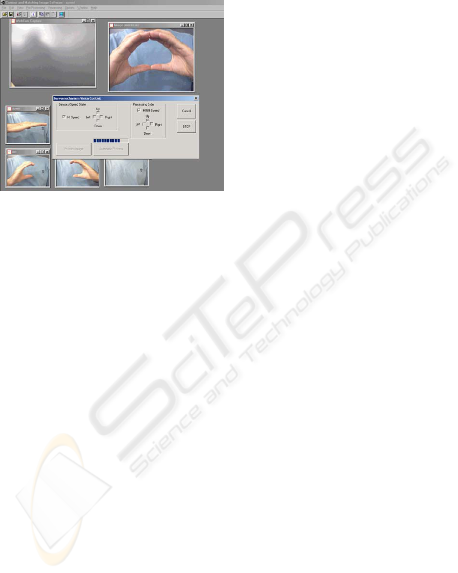
Figure 7: Servomechanism’s vision control system based
on the orientation histograms methodology
in the automatic working mode.
4 CONCLUSIONS AND FUTURE
WORK PERSPECTIVES
In this paper, was presented a servomechanism’s
vision control system based on hand gesture. The
used servomechanism was described, presented the
developed interface to its personal computer control,
and presented both approaches considered to the
control system. The first one, based in the command
object’s moments, is of simple and quick
implementation. However presents some
disadvantages, mainly the reduced number of
possible control orders. The second one is based on
image orientation histograms, and easily overcomes
this problem with a reduced computation cost
increment.
During the several experimental tests done, we
concluded that the methodology based on orientation
histograms presented two great advantages:
implementation simplicity and execution quickness.
The referred approach, works in satisfying manner
controlling the used servomechanism, and could be
considered in other kinds of friendly interfaces:
games, computerized applications, home appliances,
robotic systems, remote controls, etc.. However, we
also found that this approach presents some
limitations as well: As the used webcam does not
compensate lighting changes, the vision control
system does not react the same way if those
variations are significant. Another problem with the
actual version of the vision control system, relates
with the control object’s size and how it domain
each control image. This last problem is augmented
by the lack of an Auto-Focus system in the used
webcam.
For future work, to turn the vision control system
more robust to the problems previously referred, we
can suggest: a) The tracking of the control object
through images sequence using, for example,
Kalman filters, (Tavares, 1995), with active contours
(Blake, 1998; Tavares, 2000, 2002), as indicated in
(Blake, 1993). b) The employ of a more
sophisticated camera, which, by itself, can improve
the robustness of the adopted vision control
methodology.
REFERENCES
Blake, 1993. A. Blake, R. Curwen, A. Zisserman, “A
Framework for Spatiotemporal Control in the Tracking
of Visual Contours”, International Journal of Computer
Vision, 11(2), p. 127/145, 1993.
Blake, 1998. A. Blake, M. Isard, “Active Contours”,
Springer-Verlag, 1998.
Freeman, 1995. W. T. Freeman, M. Roth, “Orientation
histograms for hand gesture recognition”, IEEE Intl.
Workshp. on Automatic Face and Gesture Recognition,
Zurich, June, 1995.
Freeman, 1996. W. T. Freeman, K. Tanaka, J. Ohta, K.
Kyuma, “Computer Vision for Computer Games”, In
2nd International Conference on Automatic Face and
Gesture Recognition, Killington, VT, USA. IEEE,
1996.
Freeman, 1998. W. T. Freeman, D. B. Anderson, P. A.
Beardsley, C. N. Dodge, M. Roth, C. D. Weissman, W.
S. Yerazunis, H. Kage, K. Kyuma, Y. Miyake, K.
Tanaka, “Computer Vision for Interactive Computer
Graphics”, IEEE Computer Graphics and Applications,
Vol. 18, No. 3, pp. 42-53, May-June 1998.
Freeman, 1999. W. T. Freeman, P. A. Beardsley, H. Kage,
K. Tanaka, K. Kyuma, C. D. Weissman, “Computer
Vision for Computer Interaction”, SIGGRAPH
Computer Graphics Magazine, November 1999.
Jain, 1995. R. Jain, R. Kasturi, B. G. Schunk, Brian G.,
“Machine Vision”, McGraw-Hill International
Editions, Computer Science Series, 1995.
Richter, 1998. J. Richter, “Advanced Windows”,
Microsoft Press, 1998.
Tavares, 1995. J. Tavares, MSc Thesis: “Obtenção de
Estrutura Tridimensional a Partir de Movimento de
Câmara”, FEUP, 1995.
Tavares, 2000. J. Tavares, PhD Thesis: “Análise de
Movimento de Corpos Deformáveis usando Visão
Computacional”, FEUP, 2000.
Young, 1998. M. J. Young, “Mastering Microsoft Visual
C++ 6”, Sybex, 1998.
TWO APPROACHES FOR A SERVOMECHANISM CONTROL SYSTEM USING COMPUTER VISION
409
