
LASER-BASED ADAPTIVE CRUISE CONTROL FOR
INTELLIGENT VEHICLES
Miguel Ángel Sotelo, IEEE Member, David Fernández
Department of Electronics, University of Alcalá, Alcalá de Henares, Madrid, Spain
Eugenio Naranjo, Carlos González, IEEE member, Ricardo García, Teresa de Pedro, Jesús Reviejo
Department of Industrial Computer Science, Industrial Automation Institute, CSIC, Arganda del Rey, Madrid, Spain
Keywords: Intelligent Transportation Systems; Laser-based Adaptive Cruise Control; Fuzzy Logic; Vehicle
Automation
Abstract: Vehicle and highway automation is believed to reduce the risk of accident, improve safety, increase
capacity, reduce fuel consumption and enchance overall comfort and performance for drivers. One of the
most important research topics in the field of Intelligent Transportation Systems (ITS) is Adaptive Cruise
Control (ACC), aiming at adapting the vehicle speed to a predefined value while keeping a safe gap with
regard to potential obstacles. For this purpose, a laserscanner system provides the distance between the ego
vehicle and the preceding vehicle on the road. The complete system can be understood as a Laser-based
ACC controller, based on Fuzzy Logic, which assists the vehicle velocity control offering driving strategies
and actuation over the throttle of a car. This controller is embedded in an automatic driving system installed
in two testbed mass-produced cars operating in a real environment. The results obtained in these
experiments show a good performance of the Laser-based gap controller, which is adaptable to all speeds
and safe gap selections.
1 INTRODUCTION
Recent studies estimate that some 5.5 million
European Union accidents resulted in 42200
fatalities in 1998. The United States that same year
claimed another 42000 lives, and 9000 more were
lost in Japan. Overall, the cost to these nations
totalled some €682 billion, as described in (Marsh,
2003). As a result, a lot of money has been spent in
order to make roads safer. One of the applications of
ITS is to provide assistance to the control of some
vehicle elements, like the throttle pedal and
consequently, the speed-control assistance. A Cruise
Control (CC) system is a common application of
these techniques. It consists of maintaining the
vehicle speed at a user (driver) pre-set speed. These
kind of systems are already mass installed in top of
the line-end vehicles. A second and more
sophisticated step in the development of the speed
assistances is Adaptive Cruise Control (ACC)
(Crosse, 2000). ACC is similar to conventional
cruise control in that it keeps the vehicle pre-set
speed. However, unlike conventional cruise control,
this new system can automatically adjust speed in
order to maintain a proper headway distance (gap)
between vehicles in the same lane (STARDUST,
2002). In the current work this is achieved through a
laserscanner headway sensor, a PC, and a fuzzy-
logic speed controller. This paper addresses the
integration of a lasersacnner system, mechatronics,
and fuzzy control techniques in order to get robotic
aids to driving cars. The present application includes
a car computer throttle control powered by a fuzzy
logic controller, with the capability of performing a
Laser-based Adaptive Cruise Control either in an
unmanned/manual driving. The work described in
this paper was done at the Instituto de Automática
Industrial (IAI), a part of the Spanish Council for
Scientific Research (CSIC), in collaboration with the
Department of Electronics of the University of
Alcalá. The experiments were made in a private test
circuit located at the Instituto de Automática
Industrial, using two automated mass-produced
vehicles (Citroën Berlingo) as depicted in figure 1.
398
Ángel Sotelo M., Fernández D., Naranjo E., González C., García R., de Pedro T. and Reviejo J. (2004).
LASER-BASED ADAPTIVE CRUISE CONTROL FOR INTELLIGENT VEHICLES.
In Proceedings of the First International Conference on Informatics in Control, Automation and Robotics, pages 398-401
DOI: 10.5220/0001128603980401
Copyright
c
SciTePress
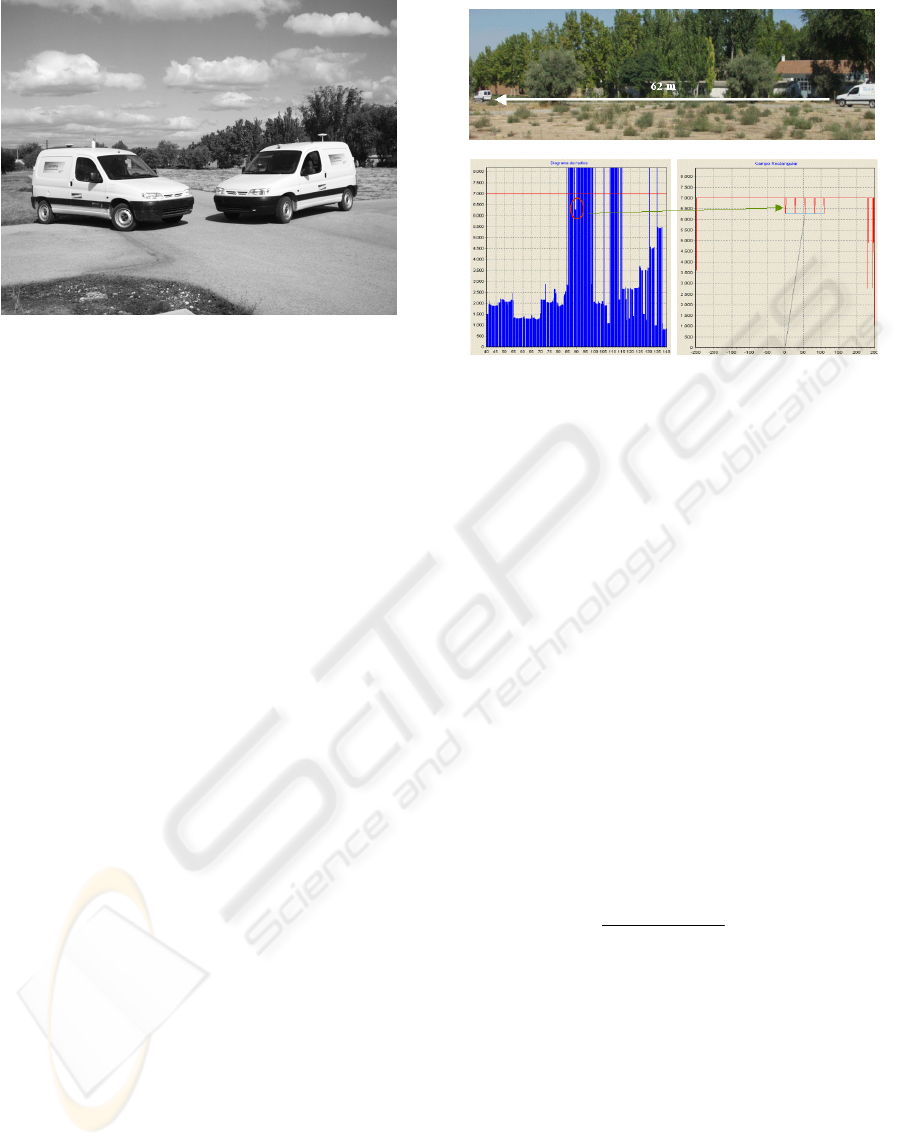
Figure 1: Citroën Berlingo commercial prototypes.
2 LASER-BASED OBSTACLE
DETECTION
A laserscanner (SICK LMS) is mounted onboard the
vehicle in order to provide reliable obstacle
detection in a range that can reach up to 90 m,
depending on weather conditions. Using the
information obtained from the laserscanner, a map
of the environment around the vehicle can be
constructed and thus, vehicle velocity can be
modified so as to track the preceding vehicle in an
adaptive cruise control manner (ACC) or to produce
an emergency stop in case of inminent collision.
Scan data provided by the laserscanner are converted
to x-y coordinates with respect to the vehicle frontal
part. Other vehicles can then be easily detected by
selecting the appropriate ROI in each situation. To
gain a better understanding on how the real system
works in real circumstances an example is presented
in which the ego-vehicle is driving along a straight
section of road, 62m behind the preceding vehicle,
as depicted in figure 2a. The angular resolution of
the SICK LMS was set to 0.25
Β
in this case, as long
as ACC is the desired feature. Distances measured
by the laserscanner at different angles are shown in
figure 2b, while the x-y coordinates of the detected
obstacles are depicted in figure 2c.
3 LASER-BASED ACC
The Laser-based Adaptive Cruise Control (ACC) is
based on a fuzzy Adaptive Cruise Control System.
Although a detailed description of the fuzzy ACC
can be found in (Naranjo et al, 2003), a brief
summary is provided.
a)
b)
c)
Figure 2: Vehicle detected on the same lane. a) Scene
picture, b) Distances measured by the laserscanner, c) x-y
coordinates of detected obstacles.
The ACC control system is based on the fuzzy
CC described in (Naranjo et al, 2003), with its
objective being to maintain a safe gap with the
vehicle ahead in the same lane of the road. Two new
input fuzzy variables, a new rule and two rule
modifications were added to the controller in order
to perform the ACC. The output is the same as that
in the CC controller: the actuation over the throttle
pedal. The pursuer car will be the automatically
driven vehicle that adapts its speed to the preceding
one. At this point, we shall define the new input
variables:
Time_Gap_current: it is the time headway, the
time it takes the pursuer vehicle to reach the point
where the pursued vehicle is at present speed, in
seconds. The mathematical representation is (1).
_
P
ursued Pursuer
current
Pursuer
xx
Time Gap
v
−
=
(1)
where x
Pursued
and x
Pursuer
are the x coordinate of the
pursued and the pursuer cars over the reference line,
in meters, and v
Pursuer
is the speed of the pursuer car
in meters per second.
Time_Gap_target: it is the time-headway set by
the user to be maintained by the ACC system from
the preceding vehicle. In commercial vehicles it
should be between 1 and 2 seconds.
Derivative of Time_Gap: is the variation of the
Time-Gap_current with time. Its mission is to
smooth the actuation in the same way that the
Acceleration smoothes the Speed_Error. The
LASER-BASED ADAPTIVE CRUISE CONTROL FOR INTELLIGENT VEHICLES
399
equation used to calculate this variable for the
control iteration i is (2).
4
__
__
4
ii
i
Time Gap Time Gap
dTimeGap
t
−
−
=
∆
(2)
Time_Gap_Error: it represents the time-gap
error, the difference between the user-defined target
time-gap and the current time-gap. Then, the input
value for the gap fuzzy controller is represented in
(3) and measured in seconds.
arg
__ _ - _
current t et
Time Gap Error Time Gap Time Gap=
(3)
We added a new rule and we also modified two
CC previous rules. The new set is as follows:
IF Speed_Error MORE THAN null THEN
Accelerator up
IF Speed_Error LESS THAN null AND
Time_Gap_Error MORE THAN near THEN Accelerator
down
IF Acceleration MORE THAN null THEN
Accelerator up
IF Acceleration LESS THAN null AND
Time_Gap_Error far THEN Accelerator down
IF Time_Gap_Error near AND d_Time_Gap negative
THEN Accelerator up
The aim of these rules is to maintain the Cruise
Control and to keep a safe distance. To do this, the
gap control only actuates when the pursuer car is
near the pursued one and it inhibits itself in other
cases, the control thus becoming the classical CC.
Let us see in detail the modified acceleration rules.
IF Speed_Error LESS THAN null AND
Time_Gap_Error MORE THAN near THEN Accelerator
down
The throttle signal decreases when the pursuer
car is near the pursued one so it will never accelerate
enough to crash with the other car.
IF Acceleration LESS THAN null AND
Time_Gap_Error far THEN Accelerator down
This rule allows stepping on the throttle only
when the pursuer car is far from the pursued one.
IF Time_Gap_Error near AND d_Time_Gap negative
THEN Accelerator up
With this rule, the control steps off the throttle
when the safe distance is near. The stabilization of
the system is the reason for the inclusion of the
derivative in this rule.
4 EXPERIMENTAL RESULTS
After installing the above defined controller in the
testbed cars, some experiments were made in order
to demonstrate its performance. These tests were
done at the CSIC’s Instituto de Automática
Industrial in Arganda del Rey, Madrid. The
experiment set consists of the combination of laser-
based safe gap maintenance and stop-and-go
capacity. Two testbed cars were used to make the
controller tests. Both of them are equipped with a
computer, an RTK-GPS receptor and Radio-
Ethernet, but only the pursuer has an onboard laser-
based ACC. The pursued is manually driven in order
to simulate real conditions in which the reactions of
the car ahead are unpredictable. The CC will be in
effect when the car is alone on the road. During the
156 seconds of this experiment, the pursued car runs
at some variable speed between 0, when the car is
stopped, and 30 Km/h. The target speed of the
pursuer car is always higher than the pursued one so,
the cruise control will only maintain this speed when
the pursuer is farther than the pre-selected safe gap.
The experiment was made in a circuit with a straight
lane with 2 Km of length, oriented from West to
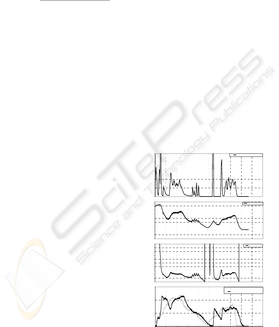
East, yielding the results depicted in figure 3.
Figure 3: Fuzzy ACC performance.
0
5
10
15
0 102030405060708090100
Time (Sec)
Speed (Km/h)
Pursued Speed (manuall y driven)
Pursuer Speed (automati cal ly driven)
0
1
2
3
4
5
6
7
8
9
10
Headway Time (Sec)
Time-Headway
0
2
4
6
8
10
12
14
16
18
Inter-Vehicle Distance (m)
Headway Distance
0
0.2
0.4
0.6
0.8
1
Pedal Pressure Normalized
Throttl e Pressure Normalized
ICINCO 2004 - ROBOTICS AND AUTOMATION
400

We have also pre-set a minimum safe headway
gap in the pursuer car of 2 seconds. The reason for
selecting this value is that 2 seconds are enough to
fulfil the safety requirements in a limited
environment such as our circuit. The bottom graphic
in figure 3 shows the real speed of both cars for the
duration of the experiment. The third graphic is the
real-time headway time-gap between these testbed
cars. The second represents the inter-vehicle
distance, in meters, including the length of the
pursued car (4 m). The top graphic shows the
pressure on the throttle of the pursued car, meaning
0 foot quite off the pedal and 1 throttle fully pressed.
At the beginning of the experiment both cars are
stopped and separated by about 50 meters. The
driver of the pursued car starts slowly while the
automatic driver of the pursued car sets the target
speed at 8 Km/h. The time gap is initially very high,
because the speeds are too low, so as the pursuer car
speed increases, the gap reduces. After the first 16
seconds, the pursuer car gets to its target speed of 20
Km/h. Then, the gap reduces drastically until it
becomes about 2 seconds. At 40 seconds from the
beginning, the pursued car stops. In this case, the
pursuer car approaches the other car until the gap is
about 2 meters (6 in the graphic), when it stops too
(STOP). The reason for this change of units is that
when the pursuer speed tends to zero, the time-gap
tends to infinity and in this case it is not useful for
control, because the cars would crash. It can be seen
in the gap graphic around the 40th second. The
distance between the cars is never less than 2 meters.
In order to improve the safety at these low speeds it
is recommended to increase the minimum safe gap
to 3 or 4 seconds.
5 CONCLUSIONS
The alliance of laser technology, fuzzy logic, and
Global Navigation Satellite Systems (GNSS) can
generate powerful controllers for automatic driving
applications. The combination of ACC+Stop&Go is
a good solution in order to achieve safer driving,
from high workload roads to traffic jams. A SICK
LMS 221 is the key element to provide obstacle
detection for active safety. By selecting a
configurable Region of Interest (ROI), the detection
ability of the laser system can be adapted to quite
different driving situations such as Adaptive Cruise
Control (tracking of a preceding vehicle on the same
lane), overtaking manoeuvres, and intersection
navigation (giving way to other vehicles before
traversing the intersection). This makes the system a
very versatile one and allows to use it either on
highways or on urban scenarios. In our experiments,
one of the testbed vehicles is manually driven while
the second vehicle is autonomously driven using the
laser-based ACC system described in this work. The
real application of this kind of technology can be
grouped in the field of intelligent driving aids.
ACKNOWLEDGEMENT
This work has been granted by several Spanish
Foundations, being the last ones: Ministery of
Science CICYT DPI2002-04064-05-04 and
Ministery of Fomento (Transports).
REFERENCES
Jones, W. D., 2001. Keeping Cars from Crashing. In IEEE
Spectrum, pp. 40 – 45.
Crosse, J., 2000. Tomorrow’s World, Automotive World,
pp. 46 – 48.
STARDUST, 2002. Scenarios and Evaluation Framework
for City Case Studies. European Comission Fifth
Framework Programme Energy, Environment and
Sustainable Development Programme Key Action 4:
City of Tomorrow and Cultural Heritage, Deliverable
2, 3.
Ioannou, P. A. and Chien, C. C., 1993. Autonomous
Intelligent Cruise Control. IEEE Transactions on
Vehicular Technology, pp. 657-672, volume 42.
Holve, R., Protzel, P., Bernasch, J., Naab, K., 1995.
Adaptive Fuzzy Control for Driver Assistance in Car-
Following. In Proceedings of the 3rd European
Congress on Intelligent Techniques and Soft
Computing – EUFIT’95, Aachen, Germany, pp. 1149-
1153.
Persson, M., Botling, F., Hesslow, E., Johansson, R.,
1999. Stop&Go Controller for Adaptive Cruise
Control. Control Applications, Proceedings of the 1999
IEEE Conference on, Vol. 2, pp. 1692-1697.
Kato, S., Tsugawa, S., Tokuda, K., Matsui, T., Fujiri, H.,
2002. Vehicle Control Algorithms for Cooperative
Driving With Automated Vehicles and Intervehicle
Communications. IEEE Transactions on Intelligent
Transportation Systems, vol. 3, No. 3, pp. 155 – 161.
Naranjo, J. E., González, C., Reviejo, J., García, R., De
Pedro, T., 2003. Adaptive Fuzzy Control for Inter.-
Vehicle gap Keeping. IEEE Transactions on
Intelligent Transportation Systems, vol. 4, No. 3.
Marsh. D., 2003. Radar reflects safer highways. EDN
Europe.
LASER-BASED ADAPTIVE CRUISE CONTROL FOR INTELLIGENT VEHICLES
401
