
AN INTEGRATED ENVIRONMENT FOR
MACHINE SYSTEM SIMULATION,
REMOTE MONITORING AND FAULT DETECTION
Amos Ng, Leo De Vin, Martin Sundberg, Fredrik Oldefors,
Centre for Intelligent Automation, University of Skövde, PO Box 408, SE-541 28 Skövde, Sweden
Philip Moore, Sanho Yeo
Mechatronics Research Group, De Montfort University, Leicester, LE1 9BH, U.K.
Keywords: Simulation, remote monitoring, model-based fault detection
Abstract: Machine service and maintenance is an intricate specialist task and machine builders often have to provide
worldwide service at short notice. Machine builders would benefit enormously from the possibility to
monitor and diagnose equipment operating at distant locations – both for condition-based preventive
maintenance and for diagnostic purposes before flying in qualified maintenance personnel and spare parts.
This paper introduces an innovative virtual engineering framework that extends the kinematics modelling
and dynamics modelling capability of advanced machine simulation systems to incorporate remote
monitoring and fault detection features. Specifically, it addresses the software environment that is designed
to facilitate the tight integration between virtual engineering tools (machine system simulation), machine
controllers (real/simulated) and model-based fault detection schemes. The underlying real-time
communication framework based on the publish-subscribe model and applications interfacing techniques
are also presented.
1 INTRODUCTION
In the past, cyclically or sporadically occurring
faults, which could not be identified automatically
and monitored directly by fault messages of the
controllers, had to be detected by visual observation
(Groll 2001). In this era of globalisation, this is not
desirable if the service and maintenance support is
provided in a worldwide basis. It is also not
applicable to machine failures for which the error
symptoms cannot be repeated for observation. Video
diagnosis systems and corresponding fast off-line
video transmission technologies, can be seen as an
enhancement to provide visual information to
improve the analysis capability (Wolfram and
Isermann 2002). However, this incorporates high
additional cost in installing and running the video
systems. Furthermore, monitoring by video can only
be applied to observe a very limited number of
views of an individual machine so that it falls short
of the applicability for monitoring the complex
machine system as a whole, where faults may occur
in different locations with different components.
Alternatively, advanced kinematics modelling with
realistic three-dimensional (3-D) animation feature
that is nowadays commonly supported by many
advanced machine simulation systems, is promising
to provide users with highly visualised, meaningful
and easily comprehensible information. This
approach is considered to be also highly economical
if the same set of simulation models, developed
incrementally during the machine design and
development lifecycle, can be reused. As a matter of
fact, our previous research conducted in the ESPRIT
project VIR-ENG (Adolfsson et al. 2000, VIR-ENG
2001, Moore et al. 2003), has proposed and
successfully demonstrated the use of virtual
engineering to support the entire development
lifecycle of modular manufacturing machine
systems, from conceptual design during negotiation
and quotation stage, to the final machine
commissioning phase. Depending on the level of
details and equipment types, both robot simulation
(RS) and discrete event simulation (DES) have been
used for developing the machine system simulations
that are integrated with real/simulated machine
150
Ng A., De Vin L., Sundberg M., Oldefors F., Moore P. and Yeo S. (2004).
AN INTEGRATED ENVIRONMENT FOR MACHINE SYSTEM SIMULATION, REMOTE MONITORING AND FAULT DETECTION.
In Proceedings of the First International Conference on Informatics in Control, Automation and Robotics, pages 150-157
DOI: 10.5220/0001129701500157
Copyright
c
SciTePress
controllers for testing and verifying the logic control
software. It has been envisaged that the graphical
simulation models developed incrementally during
the machine development stage can be effectively
applied to the operational monitoring and
maintenance phase as well. In addition to the
modelling capability and validity of the simulation
models, the applicability and effectiveness of such
an approach rely also heavily on a framework that
tightly integrates virtual engineering tools (machine
system simulations), machine controller (real and
simulated) and model-based fault detection schemes
with high-performance devices/applications
communication and interfacing techniques.
Recently, research and implementation of such a
new approach is undergoing in a Swedish project
called MASSIVE – MAchine Service Support using
Innovative Virtual Engineering at the University of
Skövde with a number of major Swedish industrial
companies (see Acknowledgments for the list of
participants). This paper aims at presenting an
overview of the MASSIVE project. Specifically, it
addresses the system architecture that is designed to
incorporate the tight integration between machine
system simulation and other system components for
remote monitoring and fault detection. It also
addresses the underlying real-time communication
framework that supports the interaction of the
system components.
The rest of this paper is organised as follows:
Section 2 briefly introduces the important modelling
concepts and techniques when using virtual
engineering tools for manufacturing machine system
lifecycles. Section 3 reveals the designed system
architecture. The underlying real-time
communication framework based on the publish-
subscribe model is presented in Section 4.
Conclusions and outlook are given in Section 5.
2 VIRTUAL ENGINEERING FOR
MANUFACTURING MACHINE
SYSTEM LIFECYCLES
Other than the advanced kinematics modelling and
realistic 3-D animation feature as mentioned
previously, the capability of virtual engineering tools
for the modelling of machine system logic as well as
the system dynamics required for both system
development and maintenance purposes should not
be underestimated. The core concept behind the new
approach proposed here is the separation of a
simulation model into a number of sub-models
including machine/environment logic models and the
machine dynamics models. These sub-models can
then readily be linked to the logic control models
and/or real/simulated machine controllers using
hardware-in-the-loop (HIL) techniques for testing
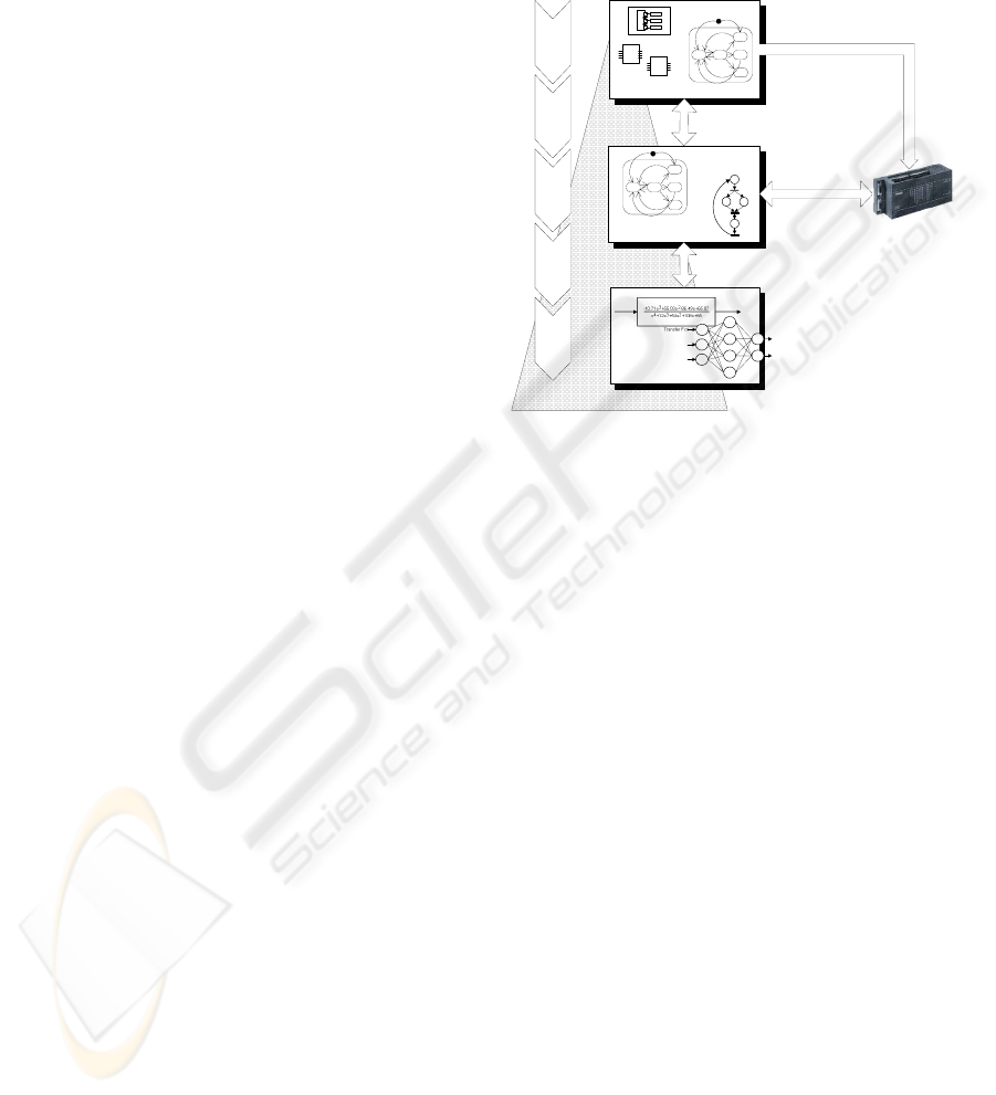
and verification. Figure 1 illustrates this concept and
proposes some suitable modelling formalisms for
different types of models.
Figure 1: Modelling techniques for manufacturing
machine system lifecycles.
A machine/environment logic model is a logic
model that mimics the logical behaviour of the
machine or process as well as part of the
surrounding environment (e.g. auxiliary devices or
human operators) in response to the commands sent
from the logic control models/machine controllers.
In return, based on the interaction of the logic model
and the machine dynamics models, inputs to the
logic control models/machine controllers are
changed to imitate the events/signals from the
feedback devices and any observable state variables
of the machine system. In other words, the
machine/environment logic model behaves as the
virtual actuators and sensors of the controlled
process. Hence, the interface for the connection to a
logic control model is called virtual I/O (VIO).
After the logic control models has been fully
tested and verified, control components that control
the physical machines can be generated seamlessly
using the VIR-ENG approach (Moore et al. 2003) or
transferred to real machine controllers such as
programmable logic controllers (PLCs). It is also
possible to carry out tests with the real controllers
against the virtual machines by replacing the virtual
sensors and actuator interfaces (i.e. VIO) with the
physical I/O devices, normally in a piecewise basis.
It has been noticed that an identical concept has been
proposed as the methodology for using the emerging
IEC 61499 function blocks modelling standard to
Design
Production &
Maintenance
Manufacturing
& Assembly
Comissioning
Integration
& Testing
FB
FB
Detail and validity of the models
Logic Control Models
e.g.
IEC 61131-3
IEC 61499
UML Statecharts
Machine/Environment
Logic Models
e.g.
UML Statecharts
Petri nets
Machine Dynamics
Models
e.g.
Linear transfer functions
Neural networks
Machine system development lifecycle
Real controller
e.g.
PLCs
Hardware-in-the-loop
techniques
Code generation
e.g. VIR-ENG approach
AN INTEGRATED ENVIRONMENT FOR MACHINE SYSTEM SIMULATION, REMOTE MONITORING AND
FAULT DETECTION
151
develop next-generation state-machine controllers
(Lewis 2001).
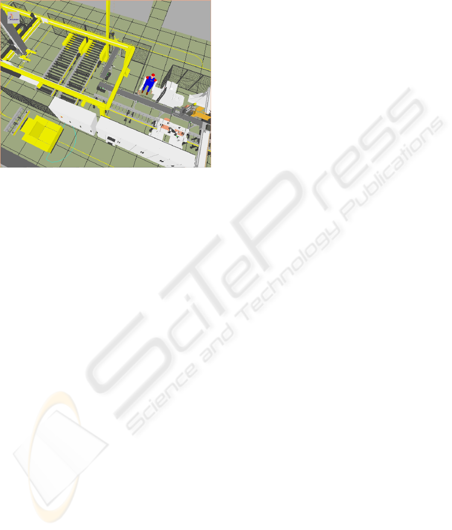
Figure 2: A simulation model for the industrial test-
bed – a flexible assembly cell for automotive engines.
The above-said approach has been partially
demonstrated to shorten the machine system
development time significantly based on the
experience from an industrial test-bed (VIR-ENG
2001) in which simulation models have been
developed using RS system IGRIP, DES system
QUEST supplied by DELMIA (2003)(see Figure 2).
To extend the model for valid and robust fault
detection further, an accurate machine dynamics
model is paramount. With an observation that
accurate machine dynamics is difficult to model by
using physical principles, especially during the
system development stage, applying system
identification techniques is proposed. Linear models
(Ljung 1999) or non-linear models, e.g. using neural
network (Nelles 2001) can be identified using
observed input-output data acquired during the
machine commissioning or initial operational stage.
These models can then be embedded into the
machine simulation and link to a
machine/environment logic model that governs
which dynamics model should be invoked based on
the predetermined logical structure. In a remote
monitoring setting, these dynamics models act as the
reference models to generate the nominal dynamic
response of the system with the input data from the
sampled data acquired remotely and allow
comparison to actual output from the real system
using residual analysis. The residual signal is useful
for fault detection, as well as to isolate and assist
diagnostic tasks when tracing the root cause of the
fault using various residual evaluation techniques –
an approach that is commonly known as model-
based fault detection. While significant efforts have
already been paid to address model-based fault
detection and isolation (FDI), particularly for the
process industry (Chen and Patton 1999, Isermann
and Ballé 1997), MASSIVE is intended to contribute
a new virtual engineering framework so that existing
generic or machine-specific FDI algorithms or
schemes, can be tightly integrated with graphical
machine simulations to provide an unique service
and maintenance environment for builders of
discrete manufacturing machine systems.
3 THE MSSS ENVIRONMENT
Within the MASSIVE project, the above-said
concepts are being realised through the design and
implementation of an integrated software
environment called MSSS (Machine Service Support
System), as an extended part of the machine design
and control environments developed in VIR-ENG. A
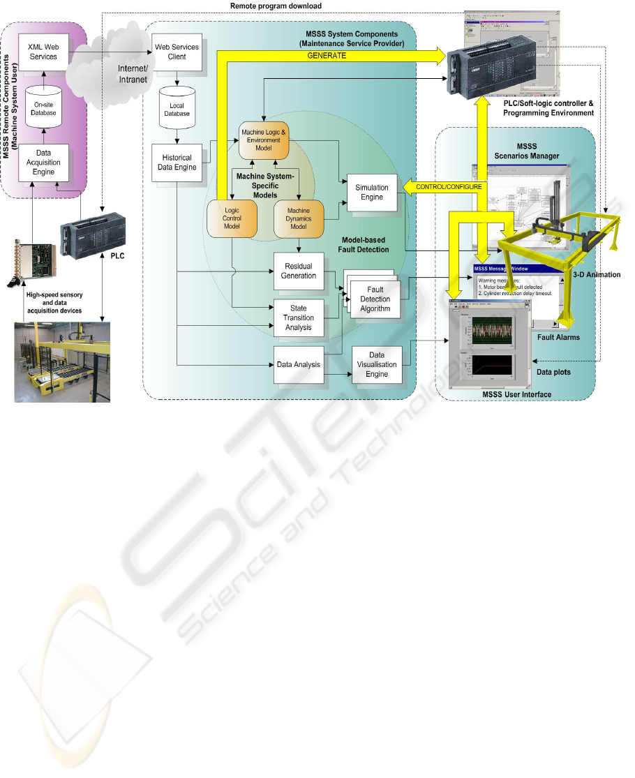
system architecture that defines various components
of MSSS and their interactions has been
preliminarily designed and is illustrated in Figure 3
on the next page.
3.1 Data Acquisition and
Transmission
MSSS is essentially a remote data acquisition and
analysis system. Therefore, it is obvious to see that
an advanced data acquisition, pre-processing and
management framework is the foundation for all
other functions. The OLE for Process Control (OPC)
technology (OPC Foundation 2003) is being used for
collecting discrete-event data and continuous data
with low sampling rate (<100Hz) from the
PLCs/soft-logic controllers or directly from the
fieldbus. As the de-facto standard for application
interface to control devices in the industrial
automation sector, OPC is supported by virtually all
automation suppliers and therefore offers seamless
data access solution without the need of developing
customised software drivers. Nevertheless, dedicated
sensory and high-speed data-acquisition devices
might be required if high sampling rate is required
for collecting continuous data such as electric
current.
The data acquisition system can be remotely
configured so that specified parameters, machine
process variables, discrete-event signals can be
acquired in prescribed time intervals and sampling
rates. Configurations for routine periodic data
logging can also be selected for day-to-day
monitoring. All configurations to the data
acquisition components are done through the Web
ICINCO 2004 - ROBOTICS AND AUTOMATION
152
methods provided by the XML Web services using
the user interface functions provided by Scenario
Manager (see Section 3.4). Implicitly, the term
“Internet/Intranet” in the system architecture implies
that a single solution can be applied readily into both
on-site and off-site machine service scenarios. This
also facilitates a common user interface for local and
remote monitoring, day-to-day and “on-demand”
specialist maintenance. Currently, the web services
are being developed using the Microsoft ASP.NET
(Active Server Page) technology. The ASP.NET
security and Windows authentication scheme have
been enforced to disallow unauthorized access to the
web services.
3.2 Monitoring and Fault Detection
For continuous visual monitoring or in the case of a
machine failure (breakdown), MSSS users can use
the historical data saved in the database to carry out
“playbacks” to investigate the recent history of the
machine system and current status using the
corresponding simulation models. In these cases,
animations are driven by the historical data acquired,
but simultaneously, the reference dynamics models
are used to generate the nominal response of the
system with the input data from the historical data.
The output data generated by the simulator and from
the collected historical data can be visualised and
compared using various data analysis and residual
analysis techniques. The data visualisation features
accomplish the 3-D animation for presenting useful
“non-animated” data like electric current and voltage
produced both from the simulator and the collected
data as an additional means for assisting any
monitoring and diagnostic tasks. A fault alarm is
generated, for instance, if a residual signal is
evaluated to exceed a certain threshold; but more
advanced fault detection algorithms can be easily
incorporated into MSSS. Figure 4 illustrates
schematically the block diagram of the monitoring
and fault detection scheme for the actuators and
mechanics of a robot manipulator.
3.3 Control System Verification
Control system verification is a desirable feature that
the simulation models can be used to verify the
control programs for testing and verification during
Figure 3: The MSSS environment.
AN INTEGRATED ENVIRONMENT FOR MACHINE SYSTEM SIMULATION, REMOTE MONITORING AND
FAULT DETECTION
153
the machine system design, development,
commissioning or re-configuration stage. While this
functionality has been explored in-depth during the
VIR-ENG project, the focus of MASSIVE is to
extend the research outcomes from VIR-ENG to
support verification of control programs that are
developed/modified to cope with maintenance
service tasks. Remote download of control code that
has been verified in a virtual environment is
particularly helpful for the following situations:
• Develop, test and upload temporary control
code in the case of temporary reconfiguration
due to machine service activities (either
preventive or corrective maintenance).
• Remote download of new/modified control
code to include additional functions requested
by the machine users during the operational
phase, e.g. to enhance the performance of the
machine or to cope with slight changes in
production.
MSSS provides control system verification with
two different types of configuration:
• Verification of logic control models and then
the logic control code is generated, compiled
and subsequently downloaded to the target
controller hardware. Verification, testing and
simulation are therefore carried out in a pure
software environment.
• Verification of the actual control logic
hardware and software.
The first configuration type has been developed
and demonstrated successfully using languages
defined in IEC 61131-3 (1993), in particular
Sequential Function Chart (SFC) as the logic control
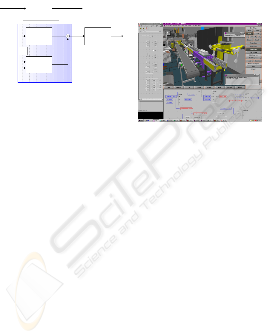
modelling language (see Figure 5). An important
research area that has recently been identified is to
extend the concept and implementation to
incorporate the function block standard defined in
IEC 61499.
Figure 5: Testing and verification of logic control
models using machine simulations.
The integration of real and simulated machine
controllers with a simulated model of the machine
system in order to test the system’s behaviour, has
been identified to be one of the “hot topics” and
technology trends of virtual manufacturing (Dépincé
et al. 2003). With today’s industrial automation
equipment, this integration can be achieved by
connecting the simulated machine/environment logic
model directly to the machine controller via the OPC
client/server-based data access technology. This
integration technique has been successfully
demonstrated by embedding OPC client functions
into a simulation system (Sundberg et al. 2003)
using the interfacing technique described in Section
4. The current challenge is to incorporate the OPC
communication capability into the unified
communication framework selected for integrating
all MSSS components (see Section 4).
3.4 Scenario Manager
Scenarios Manager is the configuration environment
for users to define/create different scenarios, e.g.
monitoring scenario, tentative failure or “what if”
scenario for diagnosis. It acts as the main user
interface for MSSS users to interact with all local
system components as well as remote components
through the Web service client. The concept of
scenarios is specifically introduced to allow users to
combine various components and sub-models in a
very flexible and rapid manner. A scenario is an
Robot
Manipulator
⎥
⎦
⎤
⎢
⎣
⎡
)(
)(
ky
ky
&
⎥
⎦
⎤
⎢
⎣
⎡
)(
ˆ
)(
ˆ
ky
ky
&
⎥
⎦
⎤
⎢
⎣
⎡
)(
)(
ke
ke
&
Robot simulation
Motion
Playback
⎥
⎦
⎤
⎢
⎣
⎡
)(
)(
ky
ky
&
Fault Detection
Al g o r i t h m
Res id ua l
Faul t
Al a r m
1−
z
Ad a pt i v e
Dynamics Model
+
-
Position &
Velocity
Torque command
T
Figure 4: Monitoring and fault detection scheme for
the actuators and mechanics of a robot manipulator.
ICINCO 2004 - ROBOTICS AND AUTOMATION
154
abstract “container” that holds any combinations of
the following types of software objects:
• A simulation model that is comprised of
various sub-models.
• Historical data stream.
• VIO variables to real/simulated control
devices/programs.
• Fault detection algorithms that can be applied
with the simulation model.
• Data processing and visualisation functions.
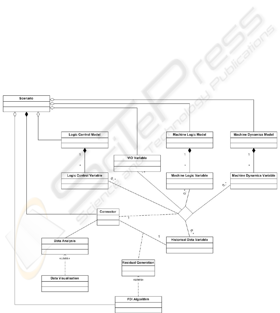
The UML (Unified Modelling Languages) class
diagram shown in Figure 6 represents the
aggregation of a scenario. A connector is a software
communication mediator that defines the interface
for related software objects to communicate with
each other, for instance, different types of sub-
models, different algorithmic modules for residual
analysis and fault detection, possibly developed
using a variety of tools and running on a distributed
platform. The purpose of having the concept of
connectors is twofold. Firstly, it reduces the
dependencies among MSSS components; a single
component or sub-model can be used and reused in
multiple scenarios without any modifications.
Secondly and more importantly, it hides the
underlying communication mechanism from the
software packages adopted in MASSIVE. In other
words, the communication mechanism is
encapsulated by the framework that supplies all the
communication functions in form of a set of
standard libraries.
4 THE COMMUNICATION
FRAMEWORK
The following issues have been considered as vital
when it comes to the development of the
communication framework:
• The suitable communication model for the
data flows within a scenario.
• How machine simulation systems are
integrated with other applications in order to
produce smooth animation effects.
Figure 6: UML class diagram showing the aggregation of a scenario.
AN INTEGRATED ENVIRONMENT FOR MACHINE SYSTEM SIMULATION, REMOTE MONITORING AND
FAULT DETECTION
155
• How data integrity and synchronisation is
maintained if multiple parties are sharing the
data concurrently.
The concept of connectors has suggested the
possibility of having some distributed, many-to-
many complex data flow patterns when running a
scenario. Loose coupling and real-time
(deterministic) performance have been identified to
be the essential requirements when selecting the
communication architecture that supports the
implementation of the connectors: it should facilitate
the dynamic configuration of data producers from
data consumers so that each can act independently of
each other; data exchange among applications
should also happen anonymously in a distributed
platform, without knowing the network locations.
After an extensive investigation into various
communication middleware architectures, such as
the well-known Microsoft’s Distributed Component
Object Model (DCOM) and Common Object
Request Broker Architecture (CORBA), the
Network Data Delivery Services (NDDS)
middleware (Pardo-Castellote et al. 1999) supplied
by Real-Time Innovations (RTI) commercially has
been selected as the most suitable one for
developing the communication framework for
MSSS. NDDS is developed based on the publish-
subscribe model that simplifies peer-to-peer and
many-to-many communications. Applications use
named topics rather than network addresses to
distribute data; a publisher simply creates a
publication and gives it a topic name. Each
subscriber then creates a subscription for the topic
name and instructs NDDS what to do when a new
issue arrives. A publisher can then update the shared
data and notify all subscribers by sending an issue
using only a single NDDS function call. Every time
the publication has a new issue, NDDS handles the
network I/O and transparently sending each issue
from the publisher to all subscribers with a declared
interest in that topic. Subscribers can therefore be
notified when data has been changed and avoid the
need for continuous polling. The publish-subscribe
model is therefore described as notification-based.
The NDDS publish-subscribe model features an
open protocol that adjusts automatically as
applications join and leave the network.
Communications happen anonymously and an
application can join and leave the network without
the need to notify others; this makes the
communications highly fault-tolerant. On the other
hand, NDDS provides fast and deterministic data
distribution over standard IP networks, whereof the
underlying UDP layer handles the data transmission
and multicast efficiently. All these features make
NDDS a very suitable middleware that satisfies the
requirements for the implementation of the
framework.
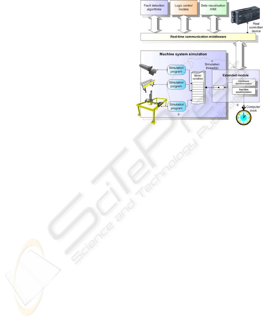
Figure 7: The interfacing method used for integrating
simulation programs with other applications.
Initial implementation of a set of standard
libraries that supports the simulation systems and
different MSSS prototype components to invoke the
NDDS services has been completed using the
simulation system interfacing technique described in
Figure 7. This interfacing technique is characterised
by the use of multithreads to detect and handle data
updates of model variables that are logically
connected to connectors. This relieves the simulation
engine from running a polling loop to detect data
changes. Together with the real-time capability of
NDDS, this results a highly smooth animation effect.
A set of experiments has been carried out to
quantitatively compare the performance of NDDS
with other architectures; NDDS outperforms DCOM
noticeably in terms of both update latency and
throughput.
5 CONCLUSIONS & OUTLOOK
This paper has introduced an innovative virtual
engineering framework for supporting the remote
monitoring, fault detection and maintenance services
of discrete manufacturing machine systems. The
core concept behind this framework is the separation
of a virtual machine (simulation model) into a
number of sub-models including logic control
models, machine/environment logic models and
machine dynamics models. This separation
ICINCO 2004 - ROBOTICS AND AUTOMATION
156

facilitates many useful advanced functions to be
developed, including control system verification,
HIL testing, monitoring by “playback” and model-
based fault detection, etc.
This paper has pointed out the importance of a
real-time communication framework that provides a
highly flexible communication mechanisms among
different sub-models and other system components,
possibly developed using a variety of tools running
on a distributed platform. RTI’s NDDS has been
selected as the suitable real-time networking
middleware for the development of the underlying
communication framework. Based on the publish-
subscribe model, NDDS provides many-to-many
communications to happen anonymously with
network location transparency, which are essential to
the implementation of connectors – the concept
introduced for maintenance specialists to define
multiple monitoring and fault detection scenarios by
flexibly connecting multiple sub-models,
algorithmic modules and data analysis tools. Future
publications will focus on the dynamics modelling
techniques and fault-detection algorithms for the
real-world industrial test cases within MASSIVE.
ACKNOWLEDGEMENTS
The authors gratefully acknowledge the Knowledge
Foundation (KK Stiftelsen), Sweden, and other
industrial participants, including AP&T, DELFOi,
Euromation, Volvo Cars and Volvo Powertrain, for
the provision of the research funding and their
collaborative input to the MASSIVE project. We
would also like to acknowledge Real-Time
Innovations for the grant of NDDS through our
participation in their University Program.
REFERENCES
Adolfsson, J., Ng, A. H. C. and Moore, P. R. (2000)
Modular machine system design using graphical
simulation. In Proceedings of the 33rd CIRP
International Seminar on Manufacturing Systems, 5-7
June, Stockholm, Sweden, pp 335-340.
Chen, J. and Patton, R. J. (1999), Robust model-based
fault diagnosis for dynamic systems, Kluwer
Academic Publishers, Dordrecht.
DELMIA (2003) IGRIP/Envision & QUEST D5 Release
12, Dassault Systemes, http://www.delmia.com.
Dépincé, P., Peer-Oliver, W. and Michael, Z. (2003)
Virtual Manufacturing, MANTYS - Thematic
Technology Trend Report.
Groll, F. (2002) Process visualization and optimization
with modern software tools. In Proceedings of the
International Symposium on Robotics, 7-11 October,
Stockholm, Sweden, pp. 193-197.
IEC 61131-3 (1993) Programmable controllers - Part 3:
programming languages, International
Electrotechnical Commission.
Isermann, R. and Ballé, P. (1997) Trends in the
application of model-based fault detection and
diagnosis of technical process, Control Engineering
Practice, 5 (5), pp. 709-719.
Lewis, R. (2001) Modelling control systems using IEC
61499, The Institution of Electrical Engineers,
London, United Kingdom.
Ljung, L. (1999). System identification: Theory for the
user, Prentice-Hall, Englewood, Cliffs, New Jersey.
Moore, P. R., Pu, J., Ng, A. H. C., Wong, C. B., Chong, S.
K., Adolfsson, J., Olofsgård, P. and Lundgren, J.-O.
(2003) Virtual Engineering: An integrated approach to
agile manufacturing machinery design and control,
Journal of Mechatronics, 13, pp. 1105-1121.
Nelles, O. (2001) Nonlinear system identification,
Springer-Verlag, Berlin, Heidelberg.
OPC Foundation (2003) http://www.opcfoundation.org.
Pardo-Castellote, G., Schneider, S. and Hamilton, M.
(1999) NDDS: The real-time publish-subscribe
middleware, Real-Time Innovations whitepaper,
http://www.rti.com.
Sundberg, M., Ng, A. H. C. and de Vin, L. J. (2003)
Distributed modular logic controllers for modular
conveyor systems. In Proceedings of the 20th
International Manufacturing Conference, Cork,
Ireland, pp. 493-500.
VIR-ENG (2001) Integrated design, simulation and
distributed control of agile modular manufacturing
machinery (VIR-ENG) ESPRIT Framework IV 25444,
final report, Final report, June.
Wolfram, A. and Isermann, R. (2002) Component based
tele-diagnosis approach to a textile machine, Control
Engineering Practice, 10, pp. 1251-1257.
AN INTEGRATED ENVIRONMENT FOR MACHINE SYSTEM SIMULATION, REMOTE MONITORING AND
FAULT DETECTION
157
