
DESIGN OF LOW DELAY BANDPASS FIR FILTERS WITH
MAXIMALLY FLAT CHARACTERISTICS IN THE PASSBAND AND
THE TRANSMISSION ZEROS IN THE STOPBAND
Yukio Mori
Department of Electronics and Communication, Salesian Polytechnic
Igusa 2-35-11, Suginami-ku, Tokyo, 167-0021 Japan
Naoyuki Aikawa
College of Engineering, Nihon University
Aza-Nakagawara 1, Tokusada, Tamura-machi, Koriyama-shi, Fukushima, 963-8642 Japan
Keywords:
Low delay, Maximally flat, Closed form transfer function
Abstract:
The large group delay of the high order FIR filters is unacceptable in some applications. Therefore, recently,
how to reduce the group delay of FIR filters has been studied intensively. To reduce the ringing in the time
domain and to maximize the stopband attenuation, it is useful to design FIR filters with maximally flat char-
acteristics in the passband and transmission zeros in the stopband. We present a mathematically closed form
transfer function of low delay bandpass FIR filters with maximally flat amplitude in the passband and the
transmission zeros in the stopband. Because of the mathematically closed form transfer function, the design-
ing filters are very simple. Moreover, we propose a design method of low delay bandpass FIR filters with
maximally flat amplitude in the passband and equiripple in the stopband by using an iterative method of a
closed form transfer function and Remez algorithm.
1 INTRODUCTION
FIR digital filters realized nonrecursively can always
be stable. FIR digital filters with exactly linear phase
characteristics can be easily designed and are impor-
tant for applications such as waveform transmission
and image processing. In (McClellan et al., 1973), an
excellent program to design the transfer function of
FIR filters with equiripple characteristics in both the
passband and the stopband haa been presented. These
filters have the disadvantages of having echoes in the
impulse response and ringing in the step response due
to their sharp cutoff frequency responses. The am-
plitude of these echoes is proportional to the ampli-
tude of the passband ripples. Consequently, FIR fil-
ters with maximally flat characteristics in the pass-
band are required (Herrmann, 1971). However, the
roll off property of these filters is not steep in the fre-
quency domain. Accordingly, to reduce echoes and
ringing and to maximize the stopband attenuation, it
is important to design FIR filters with maximally flat
characteristics in the passband and transmission ze-
ros in the stopband. The design method of such FIR
filters by Remez algorithm has been proposed (Se-
lesnick and Burrus, 1996; Aikawa and Sato, 2000).
However, since the delay of linear-phase filters is half
of filter length, the delay of linear-phase filters will
become large when high-order filters are required.
Recently, how to reduce the delay of FIR filters
have been studied intensively (Fukae et al., 1997;
Karm and McClellan, 1995; Selesnick and Burrus,
1998; Samadi et al., 2000). In (Samadi et al., 2000;
Ogata et al., 2000), the design method of the trans-
fer function of low delay FIR lowpass filters with flat
characteristics in both the passband and the stopband
has been presented. In (Samadi et al., 2000), the trans-
fer function is given in a mathematically closed form.
However, the roll off property of the filter is not steep
in the frequency domain. In (Ogata et al., 2000), the
design method of low delay FIR filters with maxi-
mally flat characteristics in the passband and equirip-
ple characteristics in the stopband by using successive
projections method has been proposed. This filter can
be reduced echoes and ringing, and maximized the
stopband attenuation. However, the mathematically
closed form transfer function of low delay bandpass
FIR filters with maximally flat characteristics in the
passband and the transmission zeros in the stopband
is not proposed.
We propose a mathematically closed form transfer
function of low delay bandpass maximally flat FIR
filters with prescribed transmission zeros in the stop-
band. This method can be easily realized the transfer
function of the filter with arbitrary center frequency
208
Mori Y. and Aikawa N. (2004).
DESIGN OF LOW DELAY BANDPASS FIR FILTERS WITH MAXIMALLY FLAT CHARACTERISTICS IN THE PASSBAND AND THE TRANSMISSION
ZEROS IN THE STOPBAND.
In Proceedings of the First International Conference on Informatics in Control, Automation and Robotics, pages 208-213
DOI: 10.5220/0001131202080213
Copyright
c
SciTePress

due to its closed form regardless of case of filter.
Moreover, we propose a design method of low delay
bandpass FIR filters with maximally flat amplitude in
the passband and equiripple in the stopband by using
an iterative method of a closed form transfer function
and Remez algorithm. Finally, the usefulness of the
proposed method is verified through the examples.
2 A CLOSED FORM TRANSFER
FUNCTION OF LOW FELAY
FIR FILTERS
In generally, a frequency response of FIR filters with
N order becomes
H(e
jω
) =
N
X
n=0
h(n)e
−jnω
= A(ω)e
jθ(ω)
(1)
where A(ω) is amplitude response and θ(ω) is phase
response. It is necessary to satisfy the following con-
ditions so that the frequency response in (1) has the
flat response in the passband, the transmission zeros
in the stopband, and the group delay response τ at
ω = ±ω
0
.
A(ω)|
ω=±ω
0
= 1 (2a)
d
m
A(ω)
dω
m
¯
¯
¯
¯
ω=±ω
0
= 0, m = 1, 2, · · · , M (2b)
A(ω
l
) = 0, l = 1, 2, · · · , L
1
+ L
2
(2c)
G(ω)|
ω=±ω
0
= −
dθ(ω)
dω
¯
¯
¯
¯
ω=±ω
0
= τ (2d)
d
m
G(ω)
dω
m
¯
¯
¯
¯
ω=±ω
0
= 0, m = 1, 2, · · · , D (2e)
where M and D are parameters to decide the degree
of flatness of amplitude response and group delay re-
sponse at ω = ±ω
0
, respectively. Moreover, L
1
and
L
2
are number of the transmission zeros in the low
stopband and in the high stopband, respectively. One
of a closed form transfer function which satisfies con-
ditions (2) is obtained as
H(e
jω
) = P (e
jω
) − R(e
jω
)S(e
jω
). (3)
We decide functions P (e
jω
), R(e
jω
) and S(e
jω
) ac-
cording to the following methods.
Consider P (e
jω
) with K degrees of flatness
P (z) =
2K
X
i=0
p
i
z
−i
= e
α(ω)+jβ(ω)
(4)
where z = e
jω
. Thus, we can be written as
φ(z) = z
P
0
(z)
P (z)
= τ
d
(ω) + jν(ω) (5)
where τ
d
(ω) and ν(ω) are differentiation the am-
plitude and the group delay of P (z), respectively.
Then, owing to simultaneous the amplitude and the
group delay having maximally flat characteristics at
ω = ±ω
0
, it should be
φ(z) = τ
P
−
B
K
¡
z
2
− 2x
0
z + 1
¢
K
P (z)
(6)
where τ
p
is the delay of P (e
jω
) and x
0
= cos ω
0
.
From (5) and (6), we obtain
−zP
0
(z) + τ
P
P (z) = B
K
¡
z
2
− 2x
0
z + 1
¢
K
. (7)
By differentiating (7) with respect to z and eliminat-
ing B
k
, we obtain
P
00
(z)
©
z
¡
z
2
− 2x
0
z + 1
¢ª
+P
0
(z)
©
(1−τ
P
)
¡
z
2
− 2x
0
z + 1
¢
−2Kz(z − x
0
)
ª
+P (z) { 2Kτ
P
(z − x
0
)} = 0
.
(8)
From (8), the coefficient p
i
of P (z) can be obtained
as eigen value problem shown by following equation.
Ap + λp = 0 (9)
where p is the column vector of coefficient p
i
and A
is (2K + 1) × (2K + 1) square matrix given by
a
i,i−1
= (τ
P
− i + 1)(2K − i + 1)
a
i,i
= −x
0
{(τ
P
− i)(2K − i) + (−τ
P
+ i)i}
a
i,i+1
= (−τ
P
+ i + 1)(i + 1)
a
i,j
= 0 ; j 6= i − 1, i, i + 1
; i = 0, 1, · · · , 2K .
(10)
Moreover, S
L−1
(z) in (3) is Lagrange interpolation
polynomial shown by the following equation.
S
L−1
(z) =
L
1
+L
2
X
i=1
F
i
L
1
+L
2
Y
j=1j6=i
z
−1
− z
−1
j
z
−1
i
− z
−1
j
(11)
where
F
i
=
P (e
jω
i
)
R(e
jω
i
)
(12)
R(e
jω
) in (3) is
R(e
jω
) =
©
(e
jω
− e
−jω
0
)(e
jω
− e
jω
0
)
ª
K+
1
2
.
(13)
In (11), z
k
= e
jω
k
is the transmission zero in the stop-
band. Thus, there are typical zero positions for each
of the four cases to obtain FIR filter with real coef-
ficient. To obtain filter of case 1, we need to select
complex conjugate pairs for all z
k
. In the case 2, we
need to select a z
k
= −1 and remainder zeros are
complex conjugate pairs. Similarly, in the case 3 and
type 4, we need to select z
k
= 1 and remainder zeros
are complex conjugate pairs and z
k
= −1 , z
k
= 1
DESIGN OF LOW DELAY BANDPASS FIR FILTERS WITH MAXIMALLY FLAT CHARACTERISTICS IN THE
PASSBAND AND THE TRANSMISSION ZEROS IN THE STOPBAND
209
and remainder zeros are complex conjugate pairs, re-
spectively. Thus, the relationship N , M, L
1
and L
2
is given by
N = M + L
1
+ L
2
. (14)
In (3), the flatness parameter of the amplitude re-
sponse, M , and group delay response, D, become
M =
½
K K : even
K + 1 K : odd
(15a)
and
D =
½
K K : even
K − 1 K : odd
(15b)
In addition, group delay at ω = ±ω
0
is given by
τ = 2K − τ
P
. (16)
It is clear from (3)-(13) that we will easily realize the
transfer function by deciding flatness in the passband
and transmission zeros in the stopband because of its
closed form function regardless of the four cases of
filter.
3 DESIGN METHOD OF
LOWDELAY FIR FILTER WITH
EQUIRIPPLE STOPBAND
In this section, we present a design method of low
delay maximally flat FIR filter with equiripple char-
acteristics in the stopband by using Remez algorithm
for the closed form transfer function in the section 2.
Using V (e
jω
) composed of zeros, z
k
= e
jω
k
(k =
1, 2, · · · , L
1
+ L
2
), in the stopband and U(e
jω
),
composed of other zeros, the transfer function in (3)
can be rewritten as
H(e
jω
) = V (e
jω
) · U(e
jω
) (17)
where
V (e
jω
) =
L
1
+L
2
Y
l=1
¡
e
jω
− e
jω
l
¢
. (18)
A zero phase transfer function doesn’t exist because
H(e
jω
) in (18) is nonlinear phase characteristics.
Then, to apply the Remez algorithm, we define the
error function as
E(e
jω
) = W (e
jω
)
©
D(e
jω
) −
¯
H(e
jω
)
ª
(19)
where W (ω) and D(ω) are a weight function and an
ideal function, respectively. Moreover,
¯
H(e
jω
in 19
is given by
¯
H(e
jω
) = H(e
jω
) · H
∗
(e
jω
) (20)
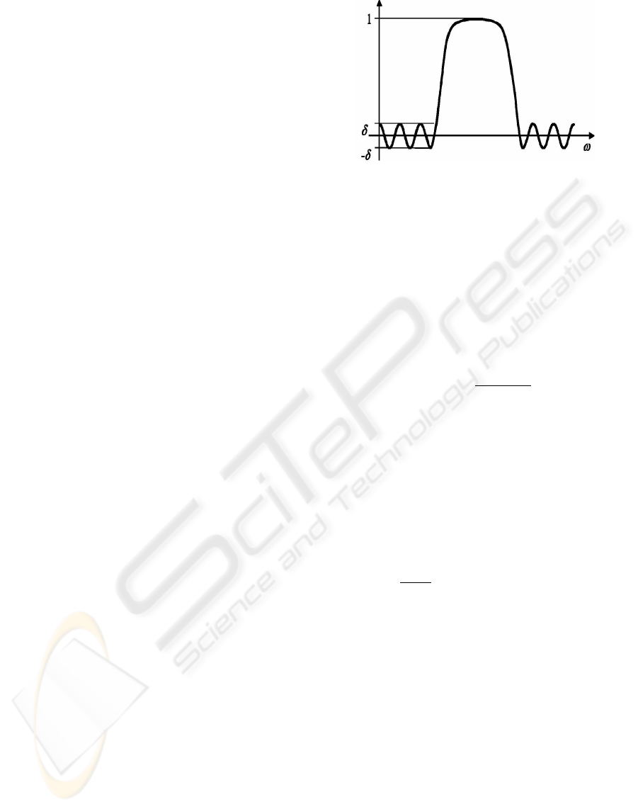
Figure 1: Amplitude response of
¯
¯
U (e
jω
)
¯
¯
2
˜
V (e
jω
)
where H
∗
(e
jω
) is a complex conjugate transfer func-
tion of H(e
jω
). Substituting (17), (18) and (20) into
(19) yields
E(e
jω
) =
ˆ
W (e
jω
)
n
ˆ
D(e
jω
) −
¯
¯
V (e
jω
)
¯
¯
2
o
(21)
where
ˆ
W (e
jω
) and
ˆ
D(e
jω
) are
ˆ
W (e
jω
) = W (e
jω
) ·
¯
¯
U(e
jω
)
¯
¯
2
(22)
and
ˆ
D(e
jω
) =
D(e
jω
)
|U(e
jω
)|
2
, (23)
respectively.
However, (21) cannot be solved directly by Remez
algorithm. Thus, we define a new error function using
˜
V (e
jω
) as
E(e
jω
) =
ˆ
W (e
jω
)
n
ˆ
D(e
jω
) −
˜
V (e
jω
)
o
. (24)
We solve (24) by Remez algorithm. Using
˜
V (e
jω
),
the amplitude response of
¯
¯
U(e
jω
)
¯
¯
2
˜
V (e
jω
) is shown
in Fig. 1. In Fig. 1, let
˜
A(e
jω
) =
1
1 + δ
n
¯
¯
U(e
jω
)
¯
¯
2
˜
V (e
jω
) + δ
o
, (25)
where δ is ripple. Then, because of
˜
A(e
jω
) > 0,
˜
A(e
jω
) can be rewritten as
˜
A(e
jω
) =
¯
¯
U(e
jω
)
¯
¯
2
¯
¯
V
M
(e
jω
)
¯
¯
2
. (26)
The zeros of V
M
(z) correspond to the zeros in the
stopband when H(e
jω
) in (17) has equiripple charac-
teristics in the stopband. It is clear from (25) and (26)
that those roots are obtained from the frequency of the
minimum value of
¯
¯
U(e
jω
)
¯
¯
2
˜
V (e
jω
).Therefore, fac-
toring is not needed in the proposed algorithm. How-
ever, the zeros of V
M
(z) do not correspond to the
zeros U (e
jω
) in (17). Thus, we assume v
k
(k =
1, 2, · · · , L
1
+ L
2
) which are roots of V
M
(e
jω
)
to be new transmission zeros and calculate (3) again.
Namely, in calculation, the filter with a complete
equiripple characteristic is not obtained once. There-
fore, the calculation of the above-mentioned is re-
peated until the transmission zeros do not vary.
ICINCO 2004 - SIGNAL PROCESSING, SYSTEMS MODELING AND CONTROL
210
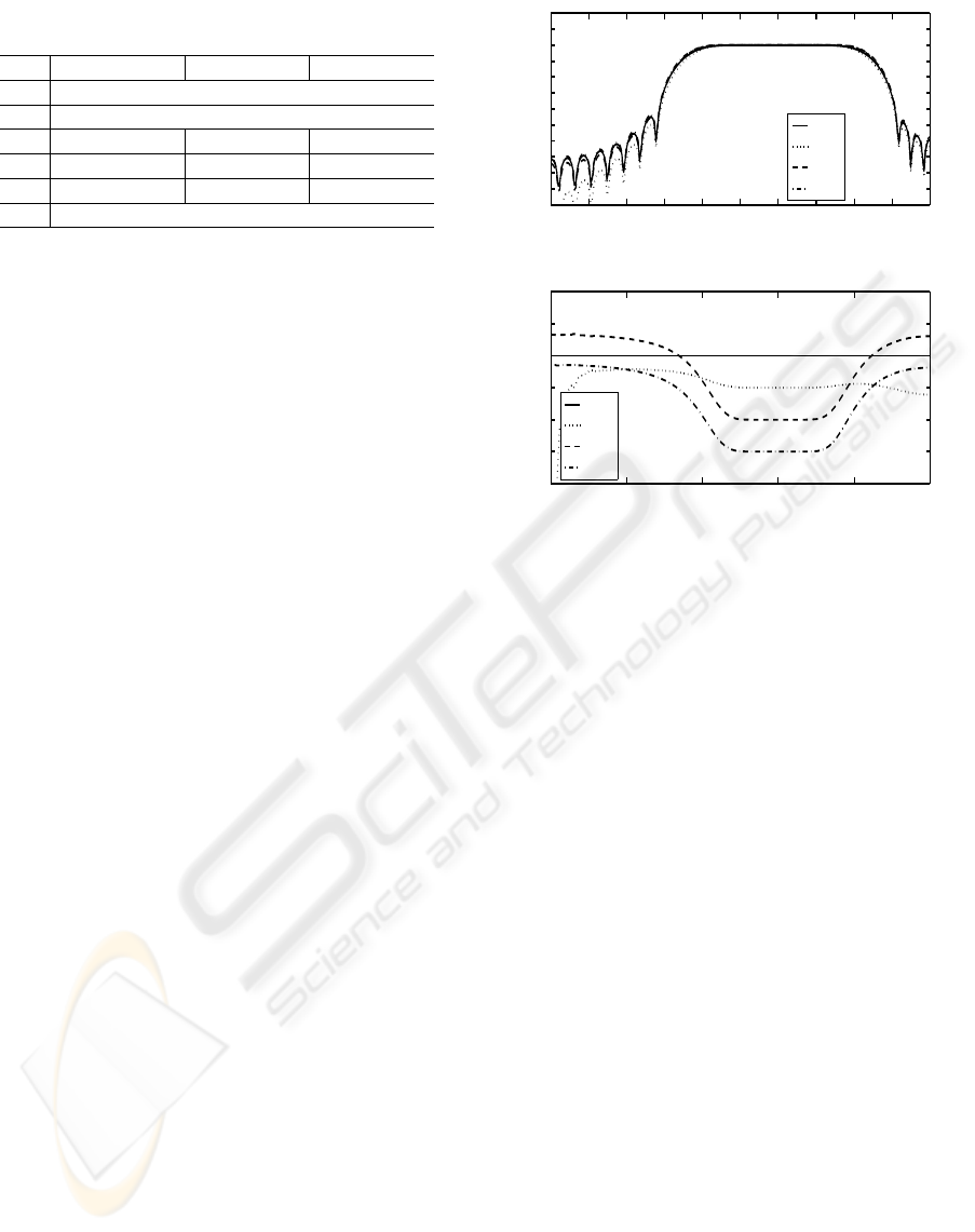
Table 1: The specifications of varying ω
0
w
0
0.15π 0.40π 0.65π
K 4
τ 18
ω
s
0.05π, 0.25π 0.30π, 0.50π 0.55π, 0.75π
L
1
2 12 20
L
2
28 18 10
N 38
4 DESIGN EXAMPLES
In this section, the usefulness of the proposed method
is verified through the examples.
We shall design all cases of bandpass maximally
flat low delay FIR filter with the prescribed transmis-
sion zeros in the stopband as following specifications.
Here, The transmission zeros in the stopband are ar-
ranged at equal intervals.
[Filter of case 1]
N = 40, K = 10, ω
0
=0.6π, τ = 20, 18, 16, 14
ω
s
=0.3π, 0.9π[rad/s], L
1
=14, L
2
=6
[Filter of case 2]
N = 39, K = 10, ω
0
=0.6π, τ = 19.5, 17.5, 15.5, 13.5
ω
s
=0.3pi, 0.9π[rad/s], L
1
= 14, L
2
= 5
[Filter of case 3]
N = 39, K = 10, ω
0
=0.6π, τ = 19.5, 17.5, 15.5, 13.5
ω
s
= 0.3π, 0.9π [rad/s], L
1
= 13, L
2
= 6
[Filter of case 4]
N = 38, K = 10, ω
0
=0.6π, τ = 19, 17, 15, 13
ω
s
= 0.3π, 0.9π [rad/s], L
1
= 13, L
2
= 5
The amplitude responses and the group delay re-
sponses of the obtained filter are shown in Fig. 5
from Fig. 2. Notice from figures (a) that the ob-
tained filters have the prescribed transmission zeros
in the stopband. Likewise, note from figures (b) that
the obtained filters have the prescribed group delay in
the passband. Moreover, when τ = 20 in case 1, the
resulting filter has a linear phase characteristics be-
cause the group delay characteristic is flat response in
all frequency as shown in Fig. 2. The same is true for
case 2, case 3 and case 4.
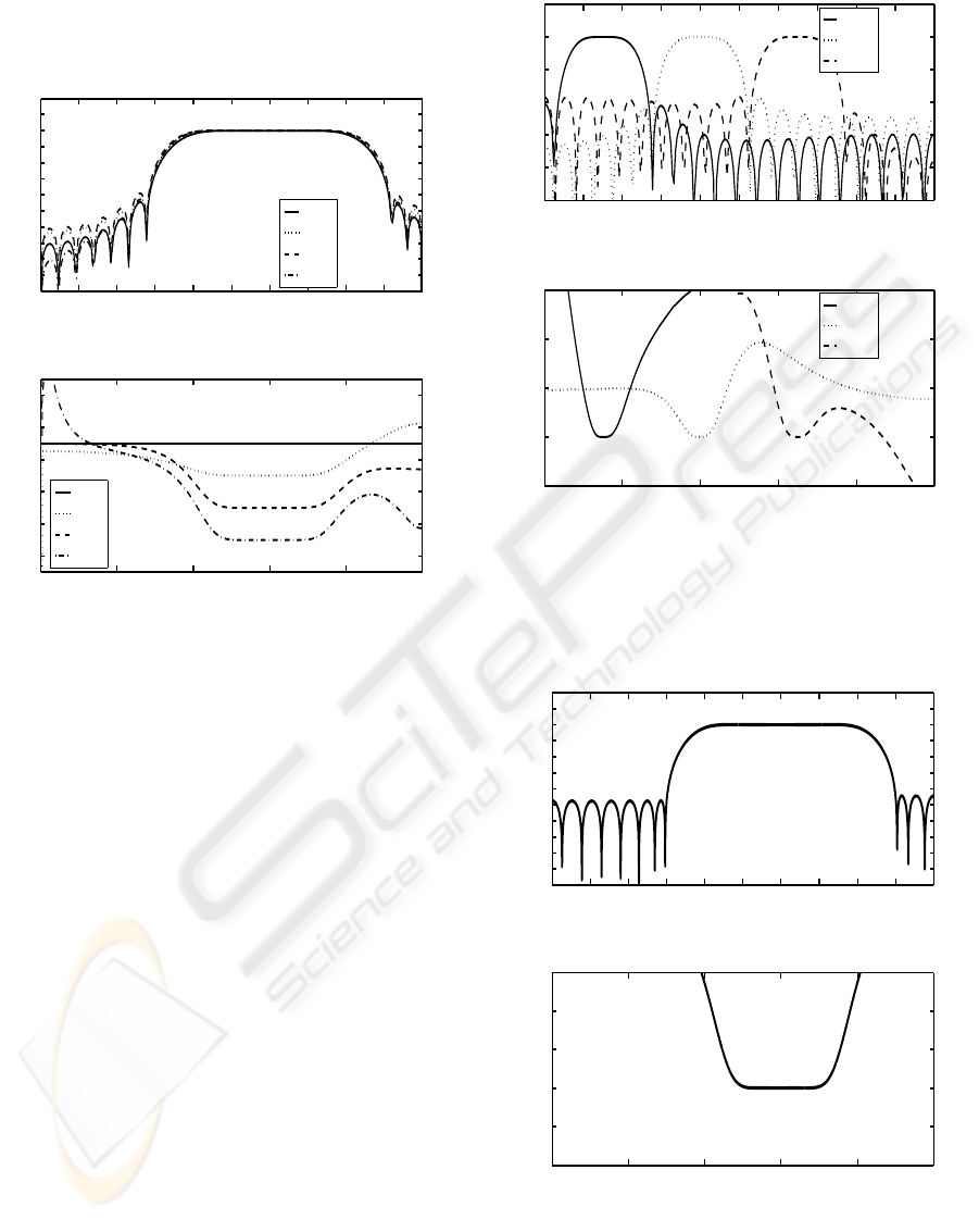
Next, we shall design the bandpass filters of case 1
with the prescribed transmission zeros in the stopband
for some center frequency as specifications in the ta-
ble 1. The amplitude response and the delay response
of the obtained filters are shown by (a) and (b) in Fig.
6, respectively. It is clear from (a) in Fig. 6 that band-
pass filter with the prescribed transmission zeros in
the stopband for the arbitrary center frequency can be
designed in the proposed method. In addition, the ob-
tained filter also has the prescribed group delay in the
passband.
Finally, we shall design a bandpass maximally flat
0 0.2 0.4 0.6 0.8 1.0
−100
−80
−60
−40
−20
0
20
Angular Frequency ×π [rad/s]
Amplitude [dB]
(a) Amplitude response
τ=20.0
τ=18.0
τ=16.0
τ=14.0
0 0.2 0.4 0.6 0.8 1.0
12
14
16
18
20
22
24
Angular Frequency ×π [rad/s]
Group Delay
(b) Group delay
τ=20.0
τ=18.0
τ=16.0
τ=14.0
Figure 2: The amplitude response and the group delay of
filter of case 1
FIR filter of case 1 with equiripple stopband as fol-
lowing specifications.
[Specifications]
N = 40, K = 8, ω
0
= 0.6π, τ = 14
ω
s
= 0.3π, 0.9π[rad/s], L
1
= 14, L
2
= 6
This specification is the same as case 1 of the first
example. Therefore, we assume the filter of case 1
that has τ = 14 to be a initial value. That is, we de-
sign a low delay bandpass maximally flat FIR filters
with prescribed transmission zeros in the stopband by
using 3 at first. The obtained amplitude response and
group delay response are shown by dashed line in Fig.
2. Next, we design a filter with equiripple characteris-
tics in the stopband by the proposed algorithm shown
in chapter 3. Here, the convergence condition of the
proposed algorithm is that the difference of angle be-
tween z
k
and v
k
is smaller than 10
−3
. In this ex-
ample, the number of iteration is three. Therefore,
convergence of the proposed algorithm is very fast.
Moreover, because the transfer function of filter with
the prescribed transmission zeros in the stopbands can
be realized the closed from and the transfer functiuon
of filter with equiripple characteristics is obtained by
Remez algorithm, its designing filter is also very sim-
ple. The amplitude response and the group delay re-
sponse of the filter obtained are shown in Fig. 7 (a)
and (b), respectively. It is clear from Fig. 7 (a) and
(b) to obtain filter with the equiripple characteristics
in the stopband and the prescribed group delayin the
DESIGN OF LOW DELAY BANDPASS FIR FILTERS WITH MAXIMALLY FLAT CHARACTERISTICS IN THE
PASSBAND AND THE TRANSMISSION ZEROS IN THE STOPBAND
211
0 0.2 0.4 0.6 0.8 1.0
−100
−80
−60
−40
−20
0
20
Angular Frequency ×π [rad/s]
Amplitude [dB]
(a) Amplitude response
τ=19.5
τ=17.5
τ=15.5
τ=13.5
0 0.2 0.4 0.6 0.8 1.0
12
14
16
18
20
22
Angular Frequency ×π [rad/s]
Group Delay
(b) Group delay
τ=19.5
τ=17.5
τ=15.5
τ=13.5
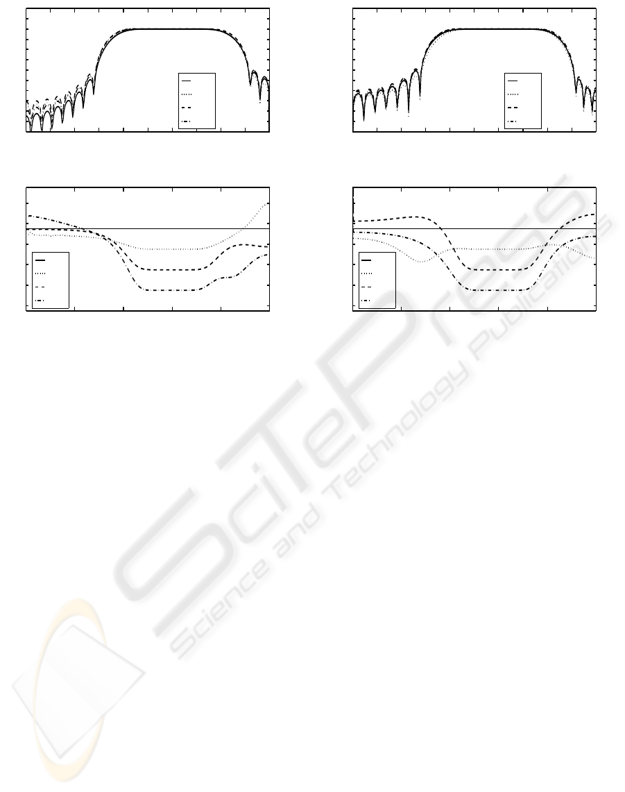
Figure 3: The amplitude response and the group delay of
filter of case 2
passband. Note that the filter obtained by this design
method differs from the filter described by chapter 2,
and can decide the stopband edge frequency, because
the Remez algorithm can decide the stopband edge
frequency.
5 CONCLUSION
We proposed a mathematically closed form transfer
function of low delay bandpass maximally flat FIR
filters with prescribed transmission zeros in the stop-
band. This method can be easily realized the transfer
function due to its closed form regardless of case of
filter. Moreover, the proposed filter has arbitrary cen-
ter frequency regardless of the even order or the odd
order. Next, we proposed a design method of low de-
lay bandpass FIR filter with maximally flat amplitude
in the passband and equiripple characteristics in the
stopband. This method is used an iterative method
of a closed form transfer function and Remez algo-
rithm. Therefore, the designing filter is also very
simple. Moreover, the proposed algorithm converges
very quickly. Finally, the usefulness of the proposed
method was verified through the examples.
This work was supported by expenditure for grad-
uate school of engineering of Nihon University in
2003.
0 0.2 0.4 0.6 0.8 1.0
−100
−80
−60
−40
−20
0
20
Angular Frequency ×π [rad/s]
Amplitude [dB]
(a) Amplitude response
τ=19.5
τ=17.5
τ=15.5
τ=13.5
0 0.2 0.4 0.6 0.8 1.0
12
14
16
18
20
22
Angular Frequency ×π [rad/s]
Group Delay
(b) Group delay
τ=19.5
τ=17.5
τ=15.5
τ=13.5
Figure 4: The amplitude response and the group delay of
filter of case 3
REFERENCES
Aikawa, N. and Sato, M. (2000). Designing linear phase fir
digital filters with flat passband and equiripple etop-
band charac-teristics. IEICE Trans., J83-A(6):744–
749.
Fukae, S., Aikawa, N., and Sato, M. (1997). Com-
plex chebyshev approximation using successive pro-
jections method. IEICE Trans., J80-A(7):1192–1196.
Herrmann, O. (1971). On the approximation problem in
non-recursive digital filter design. IEEE Trans. Circuit
Theory, CT-18(9):441–413.
Karm, L. J. and McClellan, J. H. (1995). Complex cheby-
shev approximation for fir filter design. IEEE Trans.
Circuits and Systems, CAS-42(4):207–244.
McClellan, J. H., Parks, T. W., and Rabiner, L. R. (1973).
Computer program for designing optimum fir linear
phase digital filters. IEEE Trans. Audio and Electroa-
coustics, AU-21(6):506–526.
Ogata, A., Aikawa, N., and Sato, M. (2000). A design
method of low delay bandpass filters. In ISCAS2000.
ISCAS Press.
Samadi, S., Nishihara, A., and Iwakura, H. (2000). Univer-
sal maximally flat low-pass fir systems,. IEEE Trans.
Signal Processing, 48(7):1956–1964.
Selesnick, I. W. and Burrus, C. S. (1996). Exchange al-
gorithms for the design of liner phase fir filters and
differentiators having flat monotonic passbands and
equiripple stopbands. IEEE Trans. Circuits and Sys-
temsU, CAS-43(9):671–675.
ICINCO 2004 - SIGNAL PROCESSING, SYSTEMS MODELING AND CONTROL
212
Selesnick, I. W. and Burrus, C. S. (1998). Maximally flat
low-pass fir filters with reduced delay. IEEE Trans.
Circuits and SystemsU, CAS-45(1):53–68.
0 0.2 0.4 0.6 0.8 1.0
−100
−80
−60
−40
−20
0
20
Angular Frequency ×π [rad/s]
Amplitude [dB]
(a) Amplitude response
τ=19.0
τ=17.0
τ=15.0
τ=13.0
0 0.2 0.4 0.6 0.8 1.0
12
14
16
18
20
22
Angular Frequency ×π [rad/s]
Group Delay
(b) Group delay
τ=19.0
τ=17.0
τ=15.0
τ=13.0
Figure 5: The amplitude response and the group delay of
filter of case 4
0 0.2 0.4 0.6 0.8 1.0
−40
−20
0
Angular Frequency ×π [rad/s]
Amplitude [dB]
(a) Amplitude response
ω
0
=0.15π
ω
0
=0.40π
ω
0
=0.65π
0 0.2 0.4 0.6 0.8 1.0
17
18
19
20
21
Angular Frequency ×π [rad/s]
Group Delay
(b) Group delay
ω
0
=0.15π
ω
0
=0.40π
ω
0
=0.65π
Figure 6: The amplitude response and the group delay re-
sponse of the bandpass filters for some center frequencies
0 0.2 0.4 0.6 0.8 1.0
−100
−80
−60
−40
−20
0
20
Angular Frequency ×π [rad/s]
Amplitude [dB]
(a) Amplitude response
0 0.2 0.4 0.6 0.8 1.0
12
13
14
15
16
17
Angular Frequency ×π [rad/s]
Group Delay
(b) Group delay
Figure 7: The amplitude response and the group delay re-
sponse of the bandpass filter with equiripple characteristics
in the stopband
DESIGN OF LOW DELAY BANDPASS FIR FILTERS WITH MAXIMALLY FLAT CHARACTERISTICS IN THE
PASSBAND AND THE TRANSMISSION ZEROS IN THE STOPBAND
213
