
CYCLOP SYSTEM: MOTION CONTROL OF MULTI-ROBOTS
THROUGH A SINGLE EYE
George Tho, Douglas Tavares, Pablo Alsina, Luiz Gonc¸alves
Universidade Federal do Rio Grande do Norte
DCA-CT-UFRN, Campus Universit
´
ario, Lagoa Nova, 59072-970, Natal, RN, Brasil
Keywords:
Multi-robots, landmarks, visual servor, visual control
Abstract:
We propose a way to control several robots at a glance by using visual data provided by a single vision camera.
Position and orientation of the group is given by a main robot (a master) which has a very simple camera on
its top. This robot also has two encoders for determining its positioning related to the origin. The other (slave)
robots have no position/orientation sensors as camera/angle-sensors. Their only local sensing capabilities are
light (infra-red) and bump sensors. They have a top mark that allows the master discovering their orientation
and positioning through the vision software. All robots can be controled by using a control software running
in a host computer, through a communication protocol also developed in this work. The robots have some
software tools running inside a local processor and memory so they can perform some tasks autonomously, as
obstacle avoidance. The main goal is to control all slave robots to stay inside the field of view of the master.
With this behavior, the master can have control over the slaves position and can eventually send some of them
to perform usefull tasks in certain places, inside its field of view.
1 INTRODUCTION
We propose a way to control several robots at a glance
through a vision system architecture composed by a
single camera. The camera is mounted on the top of
a mobile robotics platform, a master robot, allowing
to acquire images in real-time. Computer vision tech-
niques are used to get position and orientation of other
robots (slaves), inside the field of view of the cam-
era, in relation to the master robot. The slave robots
have a sphere on its top allowing its detection by the
vision system. All robots have local sensing capabil-
ities as infra-red light sensors, for obstacle distance,
and bump (touch) sensors. The master robot has en-
coders (angle sensors) that are used in combination
with landmarks for determining its position related to
the environment origin. All robots have a process-
ing unit that can run, locally, some small behaviors.
That is, some software tools (tasks) can be running
in its local processor and memory so they can even-
tually perform some tasks autonomously, as obstacle
avoidance. The robots can communicate to each other
and to a main computer via an infra-red port. All
robots have two motors which can be remotely con-
troled through a communication protocol also devel-
oped in this work. That is, a control software runs in
a host computer, which can repeatedly transmit con-
trol commands, in real-time, to all robots through the
communication protocol. The main goal is to con-
trol all slave robots to stay inside the field of view of
the master (as the hen and young chikens biological
behavior). With this behavior, the master can have
control over the slaves position and can eventually
send some of them to perform usefull tasks in certain
places of its field of view, individually or colectively.
It is possible that each robot has a specialized behav-
ior so that, if a mission is given to the group, each
robot can perform a part of it or some specific tasks in
parallel or sequential way.
2 RELATED WORK
Several works discuss use of visual features and
visual architectures for attention control (Treisman,
1985; Tsotsos et al., 1995). Vision is also used for
recognition purposes (Rao and Ballard, 1995; Rybak
et al., 1998). In previous work, researchers have used
vision for attention control and pattern recognition
(Gonc¸alves et al., 2000; Milanese et al., 1995). Sev-
339
Tho G., Tavares D., Alsina P. and Gonçalves L. (2004).
CYCLOP SYSTEM: MOTION CONTROL OF MULTI-ROBOTS THROUGH A SINGLE EYE.
In Proceedings of the First International Conference on Informatics in Control, Automation and Robotics, pages 339-342
DOI: 10.5220/0001133403390342
Copyright
c
SciTePress
eral works discuss robotics vision applications as a
mean to provide localization and cognition to robots,
mainly in the context of landmark selection (Milanese
et al., 1995). We used in previous work as a basis
for controling multi-user agents in a mixed reality en-
vironment, mainly given as a feedbak for the robots
controllers and also for determining their positioning
in the environment(Tavares et al., ). Several tools or
behaviors work in a bidirecional channel linking the
real platform and the virtual side of the application.
Control can be alternated betwenn real and virtual en-
tities, that is, the virtual can follow the real one, based
on its position and orientation given by the vision sys-
tem, and vice-versa, depending on a requested user
behavior. In the current work, we adopted a simi-
lar philosophy, but with the camera field of view in
horizontal positioning, that is, with camera gaze par-
allel, approximately, to the ground plane (see Figure
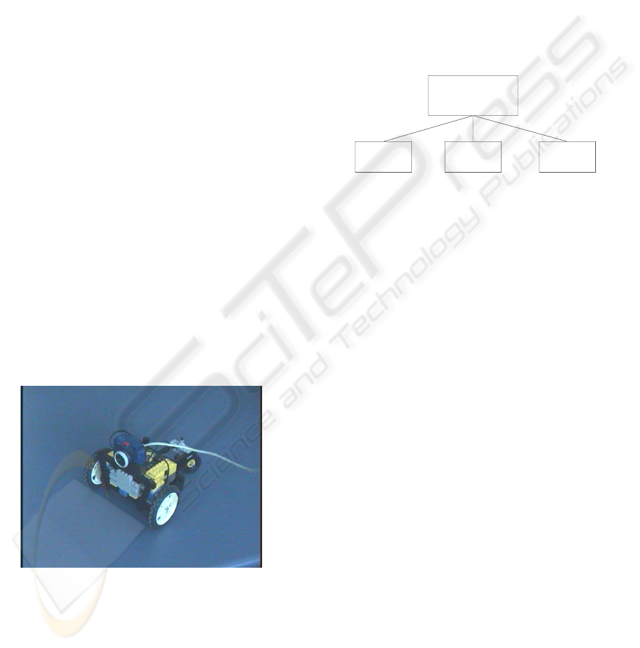
1). The environment is composed by different types
of objects as obstacles and robots. The robots are
autonomous vehicles implemented by using LEGO
hardware prototyping technology. However, we have
developed/upgraded our own software tools for con-
trol based on the BricOS operating system, once the
software provided by the fabricant of LEGO kits is
very limited. Obstacles are colored cubes or cylin-
ders. The environment can have more than one robot
so a robot could be considered as a dynamic obstacle
for another one. With this hardware setup, we can per-
form many kind of multi-robot tasks as: (1) Moving
around and avoiding obstacles; (2) Looking for spe-
cial objects (as colored cubes or cylinders); (3) Iden-
tifying and catching special objects; (4) manipulating
objects.
Figure 1: Hardware setup.
3 THE PROPOSED SYSTEM
Basically, the system has three low-level working
modules and a high-level control module as seen in
Figure 2. The first low-level module (image acquisi-
tion) is responsible for taking pictures from the cam-
era posted on the master robot and passing them to
the computer. This module runs on the host computer
and its coding depends on the hardware used for im-
age acquisition. Its output must be an array of chars
(bytes) encoding the image. This is transparent to the
vision processing, the second low-level module. This
module takes an image as input and returns position
and orientation of each robot inside the field of view.
The third low-level module (robot control) is respon-
sible for packing commands and sending them to all
robots, that is, it provides communication between the
computer and the robots.
High−level
control
Image
Acquisition
Vision
processing
Robot
control
Figure 2: System architecture.
The vision module acquires images through a digi-
tal camera posted on the top of the master robot. This
camera is capable of capturing color images up to 352
× 264 pixels in size at a rate of 30 frames per second.
It is connected to the host computer through the USB
port. The vision software developed runs under Linux
Operating System. Images are captured on the RGB
format and stored in the computer memory as an uni-
dimensional array of bytes. Each pixel is simply rep-
resented by three consecutive bytes, corresponding to
its R, G, and B component values. Vision processing
provides in real time position and orientation for each
robot inside the field of view of the robot containing
the camera. This information is determined by using
some image processing techniques to segmentate the
image followed by an algorithm for determining the
position and orientation of each detected robot.
We use a visual mark to identify each slave robot,
a sphere painted with two colors on the top of each
robot as seen in Figure 3. By finding this sphere,
we can get position and orientation of a robot. The
ball has 5 cm of diameter and is positioned approxi-
mately in the same height, in relation to the ground, as
the projection center of the camera. We consider that
the ground is a plane with same height level along it.
With that, the projection of the sphere in the image
lays, approximately, in a horizontal line passing near
the image center. This line is tracked from image to
image so its current position can be easily recovered.
The above key restrictions substantially reduce com-
putational costs.
We apply band-pass filters in the image, enhanc-
ICINCO 2004 - ROBOTICS AND AUTOMATION
340
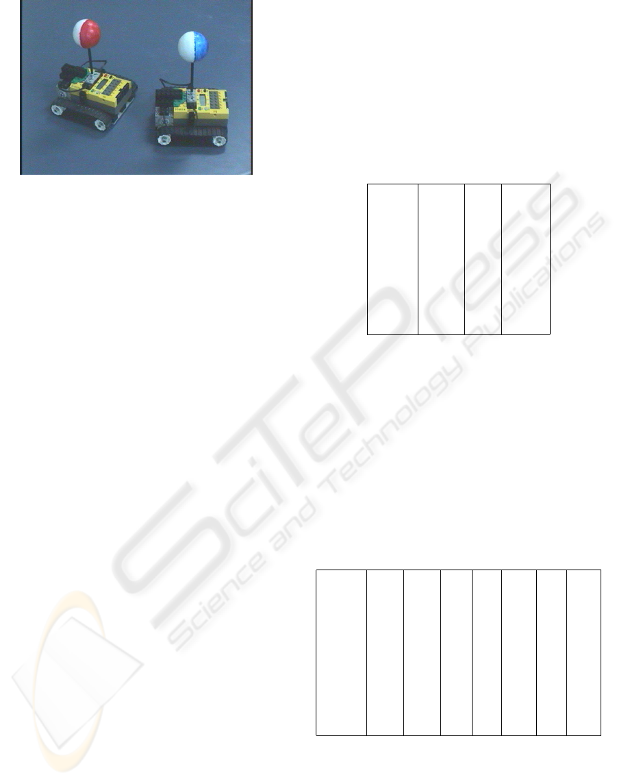
Figure 3: Two colors (red/blue and white) ball.
ing red and/or blue and white pixels. A treshold is
applied, at this time asking for pixels in two bynary
images that attend an “or” between the colors, red or
white and then blue or white. Then, we jump from 6
to 6 pixels in the image central line in order to find
a pixel inside the ball. We have, then, just to find
the edges or separations between red/blue and white.
This is done after the determination of the ball center,
by scanning the center horizontal line for an abrupt
change, in the original image. This scheme for getting
orientation makes the algorithm a little slow, running
at a 15 fps. We are currently trying to improve this
performance.
The control module is responsible for mapping the
real world into an internal geometric representation
and is responsible for generating trajectories and pass-
ing motion commands for the robots. With the ori-
entation and position of each robot been informed at
each 0.033 of a second, the control module can be
devised. We implemented a robot controller using
only position and orientation, a simple proportional
(P) one. This resulting P controller is actually com-
posed of two other P controllers working in parallel.
One is responsible for position and another for orien-
tation. At the end, the angular velocity to be applied in
each motor (wheel) is the summation of the velocity
calculated by the position controller and the velocity
calculated by the orientation controller. To control po-
sition, the reference angle θ
ref
is is the simple differ-
ence between the desired position and the actual one.
For orientation, the reference signal is given by sub-
tracting the actual value from the desired one. Finally,
having calculated the value to be applied in each of
the wheels, it is necessary to send the signal through
the infra-red tower. Several values are sent as the left
and right velocity values, and some control variables.
These values must be in the interval [0, 255] (unsigned
char). That means a minimum change for velocity can
be of 1/255 of velocity unit at each time interval.
4 EXPERIMENTS AND RESULTS
We initially conducted experiments in order to setup
the transformation between (R, X)− > (z, x) (cal-
ibration of the system). Basically, we have 12 un-
knows and each picture gives 2 equations plus one re-
striction (an orthonormal tranform matrix). So, 4 pic-
tures would be enough for finding all coefficients. As
we have taken 9 pictures, we used a minimum square
approach to perform this calculation. Table 4 summa-
rizes the taken data.
Image R X z(cm)
1 105.0 0 11
2 55.0 0 15
3 39.0 0 33
4 24.5 0 69
5 15.0 0 114
6 12.0 0 147
7 28.5 160 47
8 16.5 290 86
9 11.0 500 143
Figure 4: Data taken by hand.
Next, we tested the determination of the ball radius
in pixels by the vision system. The error in determi-
nation of the radius of the bal was up to 10%. That
means a maximum linear error up to 15 cm in the de-
termination of the robot positioning. Note that the er-
ror increases as a robot gets far from the master. Then,
we conducted some other experiments on determining
radius. Table 5 summarizes the corresponding calcu-
lated and measured by hand data. We have had no
more than 10% of error in the calculation of the robot
position.
Image Xc Yc Rc zh xh zc xc
a42 167 149 23 42 0 45 1
a43 32 149 21 42 15 41 14
a31 264 152 18 57 -15 53 -14
a32 171 151 19 57 0 56 0
a33 63 151 17 57 15 59 16
a22 170 152 16 72 0 70 2
a23 81 151 15 72 15 67 18
a11 233 154 14 87 -15 88 -13
a12 173 152 14 87 0 88 -1
a11 95 152 12 87 15 85 14
Figure 5: Data taken by hand and calculated by the system.
We conducted experiments for determining orien-
tation using two color balls. In these, the error in de-
termination of the angle was greather than 10 degrees
when the robot was close to zero or 180 degrees (re-
member origin for angle is gaze of master robot).
CYCLOP SYSTEM: MOTION CONTROL OF MULTI-ROBOTS THROUGH A SINGLE EYE
341

We also tested system performance in terms of time
spent for all calculations. For the system determining
only position (white ball), it can run in real time, up
to 30 fps. With the red/blue scheme, orientation and
position can be determined at a 10 times per minute
rate. This is also the rate in which the current version
of the communication protocol can operate in order
for the control part, so, this is fine.
5 CONCLUSIONS AND FUTURE
WORK
The proposed techique have allowed to define po-
sition and orientation of the robots using only one
single camera and a ball with two colors posted on
the top of the robot. This is a good rewsult and
this scheme can be implemented by using very sim-
ple hardware interfaces. We are currently developing
a very robust robotic platform. We will change the
LEGO robots by this one in short term. This new mas-
ter robot will have embedded processing (a PC-104)
and a stereo vision system. With this platform, we
may send the robots to other places as rooms since it is
not connected to any other computer. We also intend
to specialize the slave robots so each of them pos-
sesses a native behavior as lift objects, follow lines,
and others. Depending on the problem proposed to
the master, this one could send a specialized robot to
certain positions. In future versions, we intend to put
odometry on the slave robots so one can estimate their
positions in the images, decreasing computations nec-
essary for finding them.
We are currently developing a way to reduce un-
certainty present in the odometry system of the mas-
ter robot. A common way to do that is to make the
robot learn visually discernible marks with known po-
sition in the environment. The known coordinates of
these visually discernible marks can then be used to
correct the odometer systematic and non-systematic
errors. We have a currently implemented approach in
which we consider lines separating tiles on the ground
with known sizes to constantly update the odome-
try. Another way is to determine or to learn some
features in the environment that can be retrieved by
image filtering processes and use these feature read-
ings to try to determine a current positioning of the
robot. In principle, we intend to test with some ex-
isting techniques for landmark selection. Then to dis-
cover the best ones that can be used for detection of
useful marks in the environment. As the current posi-
tioning is supposed to be known, the robot can search
for some determined features in determined places of
its field of view, trying to identify those.
REFERENCES
Gonc¸alves, L. M. G., Grupen, R. A., Oliveira, A. A.,
Wheeler, D., and Fagg, A. (2000). Tracing patterns
and attention: Humanoid robot cognition. The Intelli-
gent Systems and their Applications, 15(4):70–77.
Milanese, R., Gil, S., and Pun, T. (1995). Attentive mecha-
nisms for dynamic and static scene analysis. Optical
Engineering, 34(8).
Rao, R. P. N. and Ballard, D. (1995). An active vision ar-
chitecture based on iconic representations. Artificial
Intelligence Magazine, 78(1-2):461–505.
Rybak, I. A., Gusakova, V. I., Golovan, A. V., Podlad-
chikova, L. N., and Shevtsova, N. A. (1998). A model
of attention-guided visual perception and recognition.
Vision Research, 38(2):387–400.
Tavares, T., Lemos, G., Medeiros, A., Tho, G., Antunes, V.,
and Gonc¸alves.
Treisman, A. (1985). Preattentive processing in vision.
Computer Graphics and Image Processing, (31):156–
177.
Tsotsos, J., Culhane, S., Wai, W., Lai, Y., Davis, N., and Nu-
flo, F. (1995). Modeling visual attention via selective
tuning. Artificial Intelligence Magazine, 78(1-2):507–
547.
ICINCO 2004 - ROBOTICS AND AUTOMATION
342
