
A LATERAL DIRECTOR AUTOPILOT DESIGN FOR CONFLICT
RESOLUTION ALGORITHMS
Mustafa Suphi Erden, Kemal Leblebicioğlu
Department of Electrical & Electronics Engineering, Computer Vision and Intelligent Systems Research Laboratory,
Middle East Technical University, 06531 Ankara, Turkey
Keywords: Aircraft autopilot, aircraft lateral dynamics, air traffic management, conflict resolution.
Abstract: Conflict resolution, namely avoidance of aircraft crushes, is one of the main problems to be solved in a free
flight based air traffic system. The researches on conflict resolution are mainly performed in simulative
environments. In the work presented here, a simple lateral director autopilot is designed for conflict
resolution studies. Using such a simple autopilot, real aircraft dynamics can be incorporated to conflict
resolution techniques and the simulation results can be made closer to real situations.
1 INTRODUCTION
In studies on the problem of conflict resolution, the
airplanes are considered to be single points able to
go in any direction pointed by the conflict resolution
algorithm (Alliot et al., 1992; Bicchi and Pallottino,
2000; Clements, 1990; Erden, 2001; Erden, 2002;
Petrick and Felix, 1998; Pappas, 1997; Tomlin,
2000). These applications are based on the
assumption that the aircrafts can be piloted in any
commanded direction, which is not the case in
reality. It is possible that the results of conflict
resolution studies might be made closer to reality by
using some simplified aircraft dynamics and
autopilots. In this study a simple lateral autopilot
(Rauw, 1998; Sachs, 1999) is designed for conflict
resolution studies in order to serve as an interface
between the dynamics and the guiding mechanisms.
2 LINEARIZED LATERAL
DYNAMICS OF AIRCRAFT
The linearized lateral dynamics equations are given
as follows (McLean, 1990):
0
0
rarp
rarp
r0
0
v
secr
tanrp
NNrNpNNr
LLrLpLLp
Ycos
U
g
rY
ra
ra
r
γψ
γφ
δδβ
δδβ
δφγββ
δδβ
δδβ
δ
=
+=
′
+
′
+
′
+
′
+
′
=
′
+
′
+
′
+
′
+
′
=
++−=
∗
&
&
&
&
&
(1)
In these equations U
0
denotes the speed of the
aircraft in the x axis direction of the aircraft body
frame, pointing forward out of the nose of the
aircraft. The subscript 0 shows that this speed is
used as the trim (linearization) condition.
β
denotes
the sideslip angle, namely it is an indication of the
angle between the x axis of the body frame and
direction of flight in the lateral plane. It is given by
(
β
=v/U
0
) for small
β
values, where v stands for the
velocity component of the aircrfat in the y direction
of the body frame, pointing out through the right
wing. If
β
is not zero, then the aircraft nose direction
is not pointing to the direction of flight in the lateral
plane. p and r denote the angular velocities (roll and
yaw rates) of the aircraft with respect to the x and z
axis of the body frame; and
φ
and
ψ
are the
corresponding roll and yaw angles.
δ
a
and
δ
r
stand
for the aileron and rudder deflections, respectively.
These two are used as the control parameters of the
lateral dynamics.
γ
0
is the angle between the relative
wind (the direction of flight) and the horizontal
plane (McLean, 1990, p.36). The subscript 0 denotes
the value used for trimming. The primed stability
derivatives appearing in the equations are dependent
on some parameters of the aircraft (surface area of
the wing, mean aerodynamic chord, wing span),
density of air, and aerodynamic coefficients of the
aircraft that are obtained from wind tunnel tests.
(McLean, 1990, pp.51-55; Stevens and Lewis, 1992,
pp.65-80)
In the simulations of this research a very large,
four-engined, passenger jet aircraft, named Charlie,
is used. The stability derivatives for lateral motion
are given in Eq 2. These values are given for a flight
condition of U
0
=158m/s,
γ
0
=0
0
, in a height level of
6100m. These data are taken from (McLean, 1990,
pp.559-561).
330
Suphi Erden M. and Leblebicio
˘
glu K. (2004).
A LATERAL DIRECTOR AUTOPILOT DESIGN FOR CONFLICT RESOLUTION ALGORITHMS.
In Proceedings of the First International Conference on Informatics in Control, Automation and Robotics, pages 330-334
DOI: 10.5220/0001133903300334
Copyright
c
SciTePress
39.0:N 0.13:L
018.0:N 0.38:L
14.0:N 0.65:L
07.0:N 2.05:L
42.0:N 0.014:Y
15.0:L 0.082:Y
ra
a
r
r
δ
r
rp
pβ
*
δ
v
−
′′
′′
−
′
−
′
−
′
−
′
′
′
−
δ
δ
β
δ
(2)
When these stability derivatives are substituted
in Eq.1, the A and B matrices of the linear system,
(3)
are as follows:
⎥
⎥
⎥
⎥
⎦
⎤
⎢
⎢
⎢
⎢
⎣
⎡
−−
−−
−−
=
00100
00010
0014.007.042.0
0038.065.005.2
0062.010082.0
A
⎥
⎥
⎥
⎥
⎦
⎤
⎢
⎢
⎢
⎢
⎣
⎡
−
=
00
00
39.0018.0
15.013.0
014.00
B
(4)
3 STRUCTURE OF THE LATERAL
DIRECTOR AUTOPILOT
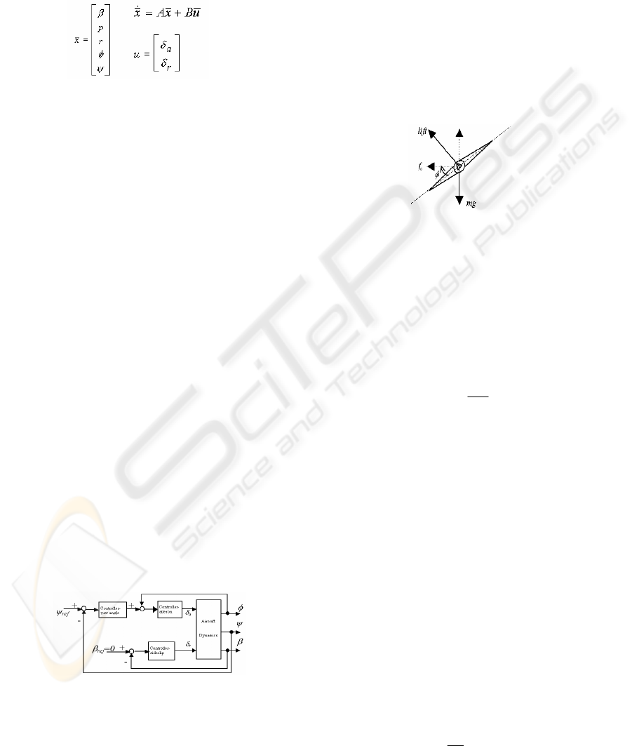
Control of the lateral motion of aircraft is managed
by manipulating the roll angle with the aileron
deflections. Therefore, Roll Attitude Hold mode
(RAH) is the basic autopilot mode for lateral
autopilots. The deviation of the actual roll angle
from the desired roll angle is fed to the ailerons.
Heading Hold mode (HH) is the lateral autopilot
mode that functions to maintain a certain heading of
the aircraft. It uses the difference between the actual
yaw angle and desired yaw angle as the feedback.
This feedback is used to determine the magnitude of
the roll angle necessary to manage the desired
heading of the aircraft. Then it uses the RAH as the
inner loop to sustain that roll angle. Besides these
two modes, turn-coordinator is another important
part of the lateral autopilot. During turnings of
aircraft an undesired sideslip angle may occur if the
flight is not coordinated. The function of turn-
coordinator is to suppress the sideslip angle with
appropriate deflections of rudder. Fig. 1 shows the
block diagram of the described lateral autopilot
model.
Figure 1: Basic lateral autopilot block diagram
4 TURNING AND COORDINATED
TURN
The basic maneuver in lateral motion is the turning
maneuver in constant level. In this maneuver the
aircraft maintains a bank angle (roll angle). Since the
body frame is banked with respect to the Earth fixed
frame the lift force in the direction of (–z) axes of
the body frame (opposite to the gravity direction if it
is not banked) is also banked. The horizontal
component of the lift force maintains the centrifugal
force (f
c
) necessary for turning, and the vertical
component balances the weight. The situation is
shown in Fig. 2.
Figure 2: The centrifugal force due to banking of the lift
force
An analysis of Fig.2 with the physical laws
relating the centrifugal force to the turning radius
will reveal that, for a constant speed flight with
velocity U
0
, the bank angle required for a turning of
w radians per second is given with the formula in
Eq. 5. This formula shows that a larger banking is
required for a sharper turn.
⎟
⎠
⎞
⎜
⎝
⎛
−
=
g
wU
tan
0
1
φ
(5)
Due to the banking of the lift force, its vertical
component decreases and is no more sufficient to
balance the weight. More deflection of the elevator
is needed for compensating the decrease in the
vertical component; otherwise the aircraft will loose
height. This is achieved by the turn-compensator in
lateral autopilots. In the analysis above and in the
simulations of this research it is assumed that the
compensation for the loss of lift is achieved by a
hypothetical turn-compensator. Therefore, the
vertical component of the lift force is always equal
to the weight, sustaining the aircraft stay in the same
level in any maneuver.
A turn is said to be ‘coordinated’ when the
lateral acceleration and the sideslip velocity (v),
hence the sideslip angle (
β
), are zero. The condition
for a coordinated turn is that the rate of change of
the sideslip angle (
β
&
) is zero. The necessary
condition for that is given by, (McLean, 1990,
p.335).
)(sin
0
φ
U
g
r =
(6)
A LATERAL DIRECTOR AUTOPILOT DESIGN FOR CONFLICT RESOLUTION ALGORITHMS
331
In any turn sideslip angle occurs if the rate of
yawing (r) is different from the value given by Eq.6.
The turn will not be coordinated in that case. If a
turning is not coordinated the derivations made on
Fig. 2 will not be valid, because the velocity vector
and the heading of the aircraft will not be pointing to
the same direction. The autopilot designed in this
work has the sideslip suppressor component as
shown in Fig. 1. This suppressor maintains the
sideslip angle close to zero during any maneuver
with proper rudder deflections. Therefore, in any
turn in simulations, Eq.6 is sustained very closely,
hence the turns may be considered to be coordinated.
5 DIRECTION CONTROL AND
LOCALIZER
In case of coordinated turns, the heading of the
aircraft can be taken as the yaw angle. This is
equivalent with the sideslip angle,
β
, being zero. For
small bank angles we can drop the ‘sin’ in Eq.5, and
write,
φψ
⎟
⎟
⎠
⎞
⎜
⎜
⎝
⎛
==
0
U
g
r
&
(6)
As Eq.6 reveals, the rate of turn of aircraft is
approximately proportional to the bank angle. A
simple direction controller for the aircraft can be in
the form,
)(
act
ref
K
comm
ψψ
ψ
φ
−=
(7)
For this control law, the ‘controller-yaw angle’
block in Fig. 1 should be filled with K
ψ
.
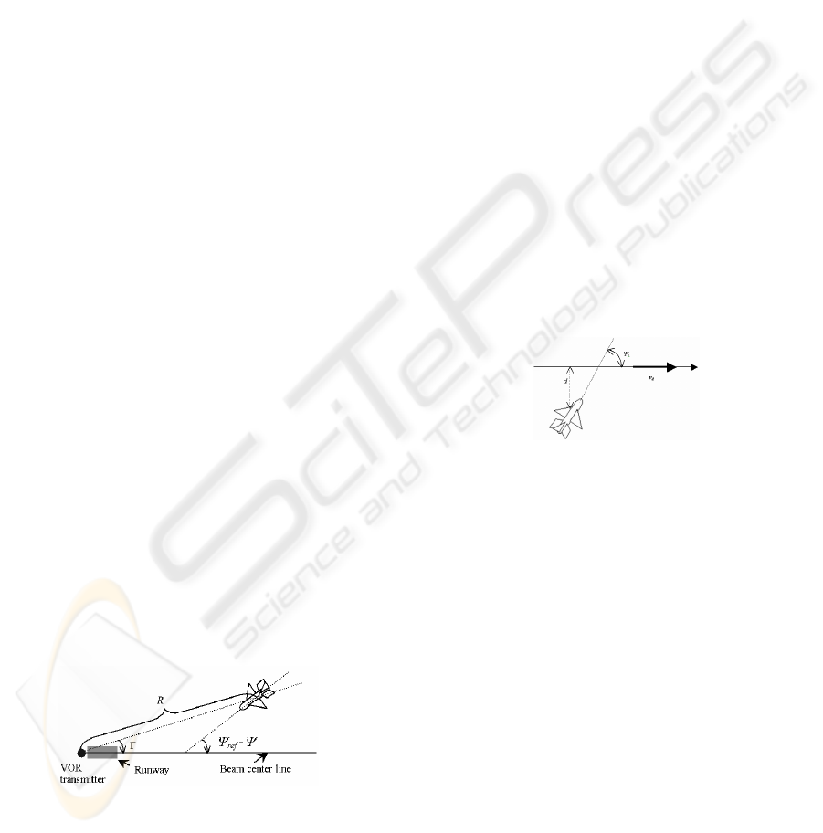
Localizing the aircraft in a desired direction is
the main concern for lateral motion control systems.
When an aircraft approaches to the airport for
landing, it should have been aligned to the direction
of runway. VHF-omni range (VOR) navigation is
the most commonly used system for this purpose.
Fig. 3 shows a graphical representation of the
system.
Figure 3: Graphical representation of VOR system
VOR navigation system makes use of the radio
navigation systems to generate the steering
commands to put the aircraft in the runway’s bearing
direction. (Nelson, 1998, pp.314-318; McLean,
1990, p.381). The information of (
Ψ
ref
-
Ψ
) and R are
used to generate the angle Γ. The output signal of
the VOR transmitter is proportional to the angle Γ,
and this signal is used to generate the
Ψ
com
command
for the director autopilot to make the Γ angle zero.
6 DESIGN OF LATERAL
DIRECTOR AUTOPILOT
The aim in this section is not to design a
sophisticated lateral autopilot, rather, to design a
suitable one sufficient to incorporate the linearized
lateral dynamics of an aircraft with any conflict
resolution algorithm. The RAH and HH modes of
the lateral autopilot will be incorporated in PID
controllers. There will be a sideslip suppressor to
strengthen the coordinated turn assumption, and the
principles of the VOR navigation system will be
utilized in a modified form.
In more concrete terms, the aim can be stated as
‘to design an autopilot to put the aircraft in any
direction in its flight level’. It is assumed that the
position and heading of the aircraft, and the direction
it should go are input to the control system, as
shown in Fig. 4.
Figure 4: Position of the aircraft and the direction it should
go in
What differs the situation in Fig. 4 from the
situation in Fig. 3 is that there is no runway, no VOR
transmitter, and no radio signal communication. The
data for the reference direction is already available
in the aircraft from the conflict resolution algorithm
without a communication process. Since there is no
VOR transmitter it is meaningless to use an angle of
Γ as in Fig. 3. It is more practical to use the
information of d and v
d
. Any ordered two points in
space determines a directed line. Let us denote this
direction with the vector v
d
and name it as the
‘direction of the line’. v
d
gives the information of
reference yaw angle. The difference between the
reference yaw and actual yaw of the aircraft will be
one of the control signals of the director. When the
heading of the aircraft is in the direction of v
d
, the
line aircraft follows will be parallel to the reference
directed line. However, these two lines are desired to
be coincident, not to be in parallel. Therefore the
information of d should be utilized to coincide the
ICINCO 2004 - ROBOTICS AND AUTOMATION
332
path of the aircraft with the reference line. The
second control signal of the director will be d. The
controller should manage to make
ψ
e
and d zero
simultaneously. In the director, the two control
signals produce two aileron deflection (
δ
a
)
commands and these are fed to the dynamics of the
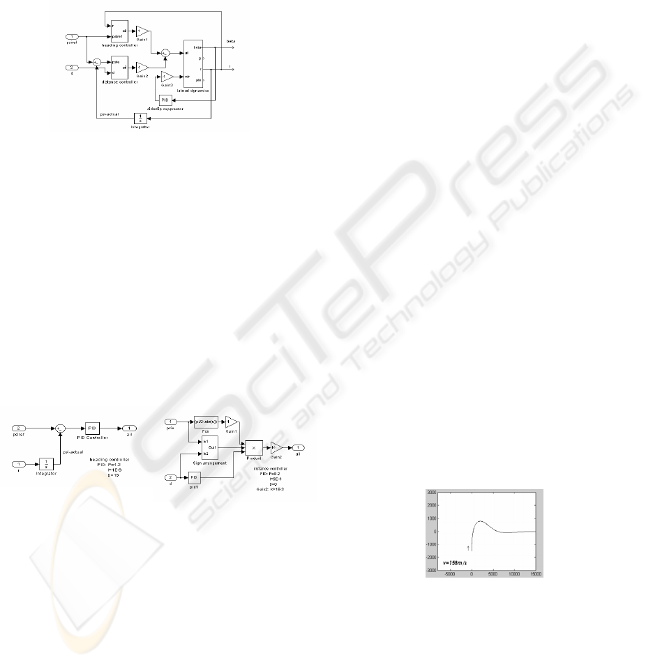
aircraft with a weighted sum. The block diagram is
given in Fig. 5.
Figure 5: Block diagram of the lateral director
The three main parts of the lateral director
autopilot are seen in Fig. 5: Heading controller,
distance controller, and sideslip suppressor. The
aileron deflection command of the heading
controller is multiplied by a weight factor and added
to the command of distance controller, which is also
multiplied with a negative weight (these weights are
arranged to be 1 for the aircraft used in simulations).
These weighting factors may be obtained by ad-hoc
methods for different aircrafts. The rudder deflection
should be negative in order to suppress a positive
sideslip angle. PID controllers are used for all
control blocks. The sideslip suppressor is simply a
PID controller. The heading controller and distance
controller blocks are shown in Fig. 6.
Figure 6: Block diagrams of the heading and distance
controllers
The PID parameters of the heading controller are
determined by ad-hoc methods. The distance
controller takes the error yaw angle (psie) with the
distance (d) and generates an aileron command. The
parameters of the PID controller and the gains in
distance controller are obtained again by ad-hoc
methods. In fact the controller is not a PID but a PI
controller since the D parameter is zero. The
function block labeled as ‘Fcn’ determines the
distance command according to the heading of the
aircraft with respect to the reference direction.
Considering Fig. 4., when the
ψ
e
is near 90
0
there is
not much need for aileron deflection to decrease the
distance, because the aircraft is already heading in
the direction to decrease the distance. On the other
hand it needs a strong aileron deviation when the
angle
ψ
e
approaches to zero. The sign arrangement
block is necessary for arrangement of sign of
distance. When the aircraft passes to the other side
of the directed line (refer to Fig. 4) the sign of the
distance becomes negative. The initial sign of the
distance should be determined properly according to
the aircraft being above or below the line, and
consistency should be attained so that the system
works properly in any configuration.
The outputs of the lateral director are taken as
the yaw angle rate (r) and the sideslip angle (
β
).
These are the necessary information to determine the
path the aircraft follows in the two dimensional
lateral plane. Although the sideslip angle is very
close to zero as a result of the sideslip suppressor,
this small value is still used in simulations. The yaw
angle of the aircraft is simply the integral of the yaw
rate. The aircraft flies with constant speed in the
direction of
ψ
actual
+
β
. The subsection performing
these calculations is called the ‘position tracker’.
7 A SAMPLE RESULT
The integration of the autopilot, dynamics of the
aircraft and the position tracker is shown in Fig. 7,
with a plot of the route that the aircraft follows in an
example situation. In this example situation, the
commanded directed line is the y=0 line with the
direction of increasing x. Accordingly, the psiref
command is made
π
/2 taking the +y direction as the
north. The d command is equal to the y position of
the aircraft. All the ad-hoc parameter arrangements
are made considering the configuration in Fig. 7.
The path is arranged to be fast enough to catch the
directed direction with little overshoot.
Figure 7: Autopilot, lateral dynamics, and position tracker
system; the path followed by the aircraft for a 90
0
right
turn in 1500m ahead
REFERENCES
Alliot, JM., H. Gruber, G. Jolly, M. Schoenauer, 1992.
Genetic algorithms for solving air traffic control
A LATERAL DIRECTOR AUTOPILOT DESIGN FOR CONFLICT RESOLUTION ALGORITHMS
333

conflicts. In Proceedings 9
th
IEEE Conference of
Artificial Intelligence Application.
Bicchi, A., L. Pallottino, 2000. On optimal cooperative
conflict resolution for air traffic management systems.
In Proceedings IEEE Transactions on Intelligent
Transportation Systems.
Clements, J.C., 1999. The optimal control of collision
avoidance trajectories in air traffic management. In
Transportation Research Part B 33 (1999) 265-280.
Erden, M.S., K. Leblebicioğlu, U. Halıcı, 2001. Çok ajanlı
system yaklaşımıyla hava trafiği kontrolü, In 9.Sinyal
İşleme ve Uygulamaları Kurultayı, Gazimağosa –
KKTC.
Erden, M.S., K. Leblebicioğlu, U. Halıcı, 2002. Conflict
resolution by negotiation. Abstract In IFAC 15
th
World
Congress Book of Abstracts, 230, Barcelona, Spain;
full paper in the related CD.
McLean, D., 1990. Automatic Flight Control Systems,
Prentice Hall International (UK) Ltd.
Nelson, R.C., 1998. Flight Stability and Automatic
Control, McGraw-Hill Companies Inc.
Pappas, G.J., C.J. Tomlin, J. Lygeros, D.N. Godbole and
S.S. Sastry, 1997. A next generation architecture for
air traffic management systems. In IEEE Conference
on Decision and Control, pp 2405-2440, San Diego,
California, USA.
Petrick, H., M. C. Felix, 1998. A soft dynamic
programming approach for on-line aircraft 4-D
trajectory optimization. In European Journal of
Operational Research 107, 87-95.
Rauw, M.O., 1998. FDC 1.2-A SIMULINK Toolbox for
Flight Dynamics and Control Analysis, Chapter 11,
February 8.
Sachs, G., 1999. Flight path predictor for minimum pilot
compensation, Aerospace Science and Technology, 4,
247-257.
Stevens B.L. and F.L. Lewis, 1992. Aircraft Control and
Simulation, John Willey & Sons Inc.
Tomlin, C., R. Ghosh, 2000. Maneuver design for multiple
aircraft conflict resolution. In Proceedings of the
American Control Conference, Chicago, Illinos.
ICINCO 2004 - ROBOTICS AND AUTOMATION
334
