
INTEGRATED DESIGN OF STRUCTURE/CONTROLLER FOR
PARALLEL INVERTED PENDULUM SYSTEMS
Chiharu Ishii and Shigehiko Yamamoto
Kogakuin University
2665-1, Nakano-cho, Hachioji-shi, Tokyo 192-0015, JAPAN
Hiroshi Hashimoto
Tokyo University of Technology
1404-1, Katakura-cho, Hachioji-shi, Tokyo 192-0982, JAPAN
Keywords:
Simultaneous optimal design, Integrated design of structure/controller, Parallel inverted pendulum systems
Abstract:
An integrated design of structure/controller for parallel inverted pendulum systems is presented. In practical
parallel inverted pendulum systems, existence of a realizable stabilizing controller is inevitably determined
depending on the position of center of gravity of two pendulums. In this paper these parameters are set as
structural parameters in structural systems and a descriptor form representation is used to express the dynamics
of parallel inverted pendulum systems. A state feedback gain and structural parameters are determined based
on a design of linear quadratic regulator(LQR), in which a generalized Ricatti equation in LQR problem for
the descriptor form representation is reduced to LMI conditions. Main contribution of this paper is to give a
method to determine the position of center of gravity of two pendulums for parallel inverted pendulum systems
in a sense of suitable for control. Based on the obtained structural parameters, some experimental works are
executed. Experimental results show the effectiveness of the proposed design method.
1 INTRODUCTION
Recently, simultaneous optimal design for structural
and control systems, in other words, integrated de-
sign of structural and control systems has attracted
an attention of control engineers (Hale, et al., 1985)
and (Pil, et al., 1996), in which structure and con-
trol system design parameters are simultaneously op-
timized to minimize a certain objective function. In
most cases, control theory gives a controller design
method for the given model of the plant. Control the-
ory seldom suggests a design of the plant itself. In
order to obtain a superior mechanism with high per-
formance, it is necessary to prepare the structural sys-
tems with higher controllability in the design stage.
In (Seto, et al., 1989), a simultaneous optimal de-
sign method for structure and control systems for an
optical servosystems is discussed, while in (Ando,
et al., 2003) this method is modified and applied to
a displacement expanders of magnetic recording test
stands. (Kim, et al., 2003) proposed a method of
simultaneous optimization for state feedback gains
and structural parameters. The system formulation
is given using descriptor form representation of the
plant under LMI(Linear Matrix Inequality) constraint.
In this paper, we propose a simultaneous optimal
design method of structure and control systems for
a parallel (double) inverted pendulum systems. It is
well known that stabilization problem of parallel in-
verted pendulum systems is very difficult compared
with the stabilization problem of single inverted pen-
dulum systems and series-type (double) inverted pen-
dulum systems. Especially, in practical parallel in-
verted pendulum systems, essential controllability is
highly depends on the length and weight of two pen-
dulums. Furthermore, existence of a realizable stabi-
lizing controller is inevitably determined depending
on the position of center of gravity of two pendulums.
If the length and the position of center of gravity of
the pendulums are not proper, realizable stabilizing
controller hardly exists in practical systems.
Analysis and stabilization control of parallel in-
verted pendulum systems is addressed in (Kawatani,
et al., 1993) and (Sugie, et al., 1993). In (Kawatani,
et al., 1993), state feedback controller with full state
observer is designed via arbitrary pole assignment.
While in (Sugie, et al., 1993), a two-degree-of-
freedom controller is designed based on H
∞
loop
shaping design procedure. In both cases, stabiliza-
tion is succeeded. However, although analysis for
the length of the pendulum is executed in both cases,
analysis for the position of center of gravity of the
108
Ishii C., Yamamoto S. and Hashimoto H. (2004).
INTEGRATED DESIGN OF STRUCTURE/CONTROLLER FOR PARALLEL INVERTED PENDULUM SYSTEMS.
In Proceedings of the First Inter national Conference on Informatics in Control, Automation and Robotics, pages 108-113
DOI: 10.5220/0001134601080113
Copyright
c
SciTePress
pendulums is not executed. In both literatures, suit-
able position of center of gravity of two pendulums
for control is determined through experiments with
adding additional weight in each pendulum by trial
and error. Thus, in structural systems, shape of the
pendulum in a sense of suitable for control in terms
of position of the center of gravity is not considered.
Therefore, in this paper we focus on the position
of center of gravity of the pendulums, and set these
parameters as structural parameters in structural sys-
tems. Main contribution of this paper is to give a
method to determine the position of center of grav-
ity of two pendulums for parallel inverted pendulum
systems in a sense of suitable for control. More
clearly, we propose a simultaneous quasi-optimal de-
sign method for state feedback gains and structural
parameters based on design of linear quadratic regu-
lator(LQR).
In the design method, firstly the plant is described
by a descriptor form representation instead of regular
state space representation. This allows to show the
structural parameters linearly in model of the plant.
Secondly, generalized Ricatti equation in LQR prob-
lem for the descriptor form representation is rewrit-
ten to TMI. By adding a proper convexifying function
to TMI, BMI is obtained from TMI. Finally, fixing
structural parameters and controller gain matrices al-
ternately, BMI reduces to LMI. Then, each feasibility
problem with LMI can be solved. This procedure is
repeated until the repetition index becomes specified
value. Thus, state feedback gain and structural param-
eters are obtained.
Based on the obtained structural parameters, in
other words, the position of center of gravity of the
pendulums, we added additional weights to the pen-
dulums so that the real position of center of gravity
becomes obtained value, and executed experimental
work for stabilization. Besides, as for the obtained
structural parameters, in terms of structural systems
design, verification through various experiments with
changing the position of center of gravity are carried
out.
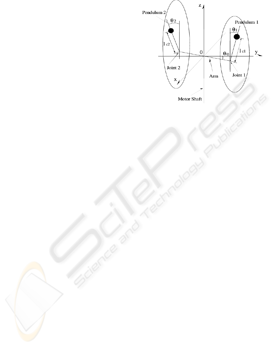
2 MODEL OF PARALLEL
INVERTED PENDULUM
Consider the parallel inverted pendulum system
shown in Fig.1.
The dynamics are given by
M(θ)
¨
θ + C(θ,
˙
θ)
˙
θ + D
˙
θ + G(θ)=τ , (1)
θ
0
: rotation angle of arm
θ
1
: rotation angle of pendulum 1
θ
2
: rotation angle of pendulum 2
m
0
: mass of arm
m
1
: mass of pendulum 1
m
2
: mass of pendulum 2
l
01
: length of arm from origin to joint 1
l
02
: length of arm from origin to joint 2
l
1
: length of pendulum 1
l
2
: length of pendulum 2
l
c0
: center of gravity of arm
l
c1
: center of gravity of pendulum 1
l
c2
: center of gravity of pendulum 2
J
0
: moment of inertia of arm
J
1
: moment of inertia of pendulum 1
J
2
: moment of inertia of pendulum 2
d
0
: viscosity coefficient of joint 0
d
1
: viscosity coefficient of joint 1
d
2
: viscosity coefficient of joint 2
g : acceleration of gravity
Figure 1: Model of Parallel Inverted Pendulum
θ =
θ
0
θ
1
θ
2
T
, τ =
τ
0
00
T
,
M(θ)=
⎡
⎣
∗1 f
3
cos θ
1
f
7
cos θ
2
f
3
cos θ
1
f
4
0
f
7
cos θ
2
0 f
8
⎤
⎦
,
∗1=f
1
+ f
2
sin
2
θ
1
+ f
6
sin
2
θ
2
,
C(θ,
˙
θ)=
⎡
⎣
∗2 −f
3
˙
θ
1
sin θ
1
−f
7
˙
θ
2
sin θ
2
∗30 0
∗40 0
⎤
⎦
,
∗2=2f
2
˙
θ
1
sin θ
1
cos θ
1
+2f
6
˙
θ
2
sin θ
2
cos θ
2
,
∗3=−f
2
˙
θ
0
sin θ
1
cos θ
1
, ∗4=−f
6
˙
θ
0
sin θ
2
cos θ
2
,
D =
⎡
⎣
d
0
00
0 d
1
0
00d
2
⎤
⎦
,G(θ)=
⎡
⎣
0
−f
5
sin θ
1
−f
9
sin θ
2
⎤
⎦
.
where θ is angle vector of arm and pendulum, M (θ)
is moment of inertia matrix, C(θ,
˙
θ)
˙
θ is nonlinear
vector containing Coriolis and Centrifugal forces, D
INTEGRATED DESIGN OF STRUCTURE/CONTROLLER FOR PARALLEL INVERTED PENDULUM SYSTEMS
109

is viscosity matrix, G(θ) is gravitational vector and
τ
0
is input torque for arm. Moreover, the following
notations are used for simplicity.
f
1
= J
0
+ m
0
l
2
c0
+ m
1
l
2
01
+ m
2
l
2
02
,
f
2
= m
1
l
2
c1
,
f
3
= m
1
l
01
l
c1
,
f
4
= J
1
+ m
1
l
2
c1
,
f
5
= m
1
gl
c1
,
f
6
= m
2
l
2
c2
,
f
7
= m
2
l
02
l
c2
,
f
8
= J
2
+ m
2
l
2
c2
,
f
9
= m
2
gl
c2
.
Consider a linear approximation for the system (1)
around the equilibrium θ
0
=[000]
T
. Then, lin-
earized system of (1) is described by
M
l
¨
θ + D
˙
θ + G
l
θ = τ , (2)
where
M
l
=
⎡
⎣
f
1
f
3
f
7
f
3
f
4
0
f
7
0 f
8
⎤
⎦
,G
l
=
⎡
⎣
00 0
0 −f
5
0
00−f
9
⎤
⎦
.
Define state variable x by x =[θ
˙
θ ]
T
. Then,
descriptor form representation of the parallel inverted
pendulum system is given by
E
˙
x = Ax + Bτ , (3)
where
E =
I 0
0 M
l
,A=
0 I
−G
l
−D
,B =
0
I
.
Note that E is a positive symmetric matrix. Hence,
equation (3) can be reformed to a regular state space
representation by pre-multiplying E
−1
. However,
since E involves structural parameters, the descriptor
form representation is used thorough this paper in or-
der to make it easy to deal with structural parameters
in structural systems.
In this paper, we focus on the position of center of
gravity for twopendulums, so other parameters in par-
allel inverted pendulum systems are set as constant.
Using a formula to calculate moment of inertia, f
4
and f
8
are expressed as follows.
f
4
= J
1
+ m
1
l
2
c1
=
1
3
m
1
l
2
1
− m
1
l
1
l
c1
+2m
1
l
2
c1
f
8
= J
2
+ m
2
l
2
c2
=
1
3
m
2
l
2
2
− m
2
l
2
l
c2
+2m
2
l
2
c2
In order to parameterize l
c1
and l
c2
linearly, the fol-
lowing approximation is adopted.
m
1
l
2
c1
≈ m
1
l
1
l
c1
,m
2
l
2
c2
≈ m
2
l
2
l
c2
Thus, f
4
and f
8
are described as
f
4
=
1
3
m
1
l
2
1
+ m
1
l
1
l
c1
,f
8
=
1
3
m
2
l
2
2
+ m
2
l
2
l
c2
.
Let l
c1
and l
c2
be structural parameters in structural
system. Then, M
l
and G
l
are described as follows.
M
l
= M
0
+ B
M
ΣC
M
,G
l
= G
0
+ B
G
ΣC
G
,
where
M
0
=
⎡
⎣
f
1
00
0
1
3
m
1
l
2
1
0
00
1
3
m
2
l
2
2
⎤
⎦
,
B
M
=
⎡
⎣
0 m
1
l
01
0 m
2
l
02
m
1
l
01
m
1
l
1
00
00m
2
l
02
m
2
l
2
⎤
⎦
,
C
M
=
⎡
⎢
⎣
100
010
100
001
⎤
⎥
⎦
,G
0
=
⎡
⎣
000
000
000
⎤
⎦
,
B
G
=
⎡
⎣
0000
−m
1
g 000
00−m
2
g 0
⎤
⎦
,
C
G
=
⎡
⎢
⎣
010
000
001
000
⎤
⎥
⎦
,
Σ=
⎡
⎢
⎣
l
c1
000
0 l
c1
00
00l
c2
0
000l
c
2
⎤
⎥
⎦
.
Note that Σ is diagonal matrix whose elements are
composed by structural parameters. Thus, descriptor
form representation (3) is rewritten as
(E
0
+ B
E
ΣC
E
)
˙
x =(A
0
+ B
A
ΣC
A
)x + B
0
τ
0
, (4)
where
E
0
=
I 0
0 M
0
,B
E
=
0
B
M
,
A
0
=
0 I
−G
0
−D
,B
A
=
0
−B
G
,
C
E
=[0C
M
],C
A
=[C
G
0],
B
0
=[000100]
T
.
3 INTEGRATED DESIGN OF
STRUCTURE/CONTROLLER
For the system (4), consider the linear quadratic reg-
ulator(LQR) problem, which is stated as follows.
LQR Problem:
Find a state feedback gain which minimizes the fol-
lowing quadratic cost function
J =
∞
0
x
T
Qx + τ
T
0
Rτ
0
dt, (5)
ICINCO 2004 - SIGNAL PROCESSING, SYSTEMS MODELING AND CONTROL
110

where Q ≥ 0 and R>0 are arbitrary matrices with
suitable dimension.
It is well known that the solution of the problem is
given as follows.
Theorem 1:
Assume that (E, A, B) in the system (3) is impulse
controllable and finite dynamics stabilizable. Then,
the state feedback gain which minimizes the quadratic
cost function (5) is given by K = −R
−1
B
T
X
g
,
where X
g
is a solution of the following generalized
Ricatti equation.
A
T
X
g
+ Y
g
A + Q − Y
g
BR
−1
B
T
X
g
=0, (6)
E
T
X
g
= Y
g
E. (7)
Then, minimum value of the cost function is given by
J
min
= x
0
E
T
X
g
x
0
.
Noting that there exists E
−1
, Ricatti equation (6) is
rewritten as follows.
PE
−1
A + A
T
E
−T
P
−PE
−1
BR
−1
B
T
E
−T
P + Q =0, (8)
where P = E
T
X
g
.
Hereafter for theoretical development, consider the
Ricatti inequality instead of Ricatti equation (8).
Using a change of variable and Schur Complement
and noting equation (4), finally the following matrix
inequality is obtained.
⎡
⎣
∗1 ∗2 ∗3
∗2
T
−I 0
∗3
T
0 −R
−1
⎤
⎦
< 0, (9)
where
∗1=(A
0
+ B
A
ΣC
A
)X(E
0
+ B
E
ΣC
E
)
T
+(E
0
+ B
E
ΣC
E
)X(A
0
+ B
A
ΣC
A
)
T
−B
0
M(E
0
+ B
E
ΣC
E
)
T
− (E
0
+ B
E
ΣC
E
)M
T
B
T
0
,
∗2=(E
0
+ B
E
ΣC
E
)XH
T
,
∗3=(E
0
+ B
E
ΣC
E
)M
T
,
X = P
−1
,Q= H
T
H, M = FX, F = −K.
(9) is a trilinear matrix inequality(TMI) of the prod-
uct of two variables X and Σ. (1, 1)-block of (9) is
described as
A(Σ)XE
T
(Σ) + E(Σ)XA
T
(Σ)
−B
0
ME
T
(Σ) − E(Σ)M
T
B
T
0
=(A(Σ)X − BM)(A(Σ)X − BM)
T
+ E(Σ)E
T
(Σ)
−(A(Σ)X − BM − E(Σ))(A(Σ)X − BM − E(Σ))
T
,
where A(Σ) = A
0
+ B
A
ΣC
A
and E(Σ) = E
0
+
B
E
ΣC
E
. Define G(Σ,X,M) as
G(Σ,X,M)=A(Σ)X − BM − E(Σ). (10)
By adding a positive semi-definite function, so-
called convexifying function proposed in (Simomura,
et al., 1993) given by
(G(Σ,X,M) − G(Σ
f
,X
f
,M
f
))
×(G(Σ,X,M) − G(Σ
f
,X
f
,M
f
))
T
≥ 0 (11)
to (1, 1)-block in (9), finally the following bilin-
ear matrix inequality(BMI) is obtained as a sufficient
condition of (9).
⎡
⎢
⎢
⎢
⎢
⎣
∗4 ∗5 ∗6 ∗7 ∗8
∗5
T
−I 000
∗6
T
0 −R
−1
00
∗7
T
00−I 0
∗8
T
000−I
⎤
⎥
⎥
⎥
⎥
⎦
< 0, (12)
where
∗4=G(Σ
f
,X
f
,M
f
)G
T
(Σ
f
,X
f
,M
f
)
−G(Σ,X,M)G
T
(Σ
f
,X
f
,M
f
)
−G(Σ
f
,X
f
,M
f
)G
T
(Σ,X,M)
∗5=E(Σ)XH
T
,
∗6=E(Σ)M
T
,
∗7=A(Σ)X − BM,
∗8=E(Σ),
Σ
f
, X
f
and M
f
are proper matrices with suitable
dimention.
BMI problem can be solved recursively by fix-
ing each variable alternately. Thus, fixing (X, M)
and Σ alternately, each feasibility problem with LMI
can be solved. However, there is no guarantee that
the parameters are adjusted desirably if only feasibil-
ity problem is considered. Therefore, suitable index
function should be introduced to obtain desirable pa-
rameters.
Generally, it is said that pendulum having its posi-
tion of center of gravity in high position can be sta-
bilized easier than that having it in low position, and
when the difference of natural frequency between two
pendulums is large, stabilization becomes easy.
In terms of these reasons, we try to raise the posi-
tion of center of gravity for long pendulum and lower
the position of center of gravity for short pendulum.
To this end, we consider to make the following index
function small.
J
l
= −
l
c1
l
0
c1
+
l
c2
l
0
c2
, (13)
where l
0
c1
and l
0
c2
are original position of center of
gravity for two pendulums. Note that the index func-
tion (13) is linear function related to the variable
{l
c1
l
c2
}. Hence, it can be solved by minimization
problem in the framework of LMI.
Thus, the algorithm to obtain a solution is stated as
follows.
INTEGRATED DESIGN OF STRUCTURE/CONTROLLER FOR PARALLEL INVERTED PENDULUM SYSTEMS
111
• Set an initial value Σ
0
= diag{ l
0
c1
l
0
c
1
l
0
c2
l
0
c2
}, and
find (X
0
,M
0
) subject to (9), where l
0
c1
and l
0
c2
are
original position of center of gravity for two pen-
dulums.
• Set a repetition index values ε
1
and ε
2
, and set k =
0.
Repeat
• Minimization problem:
By fixing (X, M)=(X
f
,M
f
)=(X
k
,M
k
), find
Σ
k+1
such that index function J
l
given by (13) is
minimized subject to (12).
• Feasibility problem:
By fixing Σ=Σ
f
=Σ
k+1
, find (X
k+1
,M
k+1
)
subject to (12).
• Set k = k +1.
Until |l
0
c1
− l
k
c1
| >ε
1
or |l
0
c2
− l
k
c2
| >ε
2
.
Note that parameters l
k
c1
and l
k
c2
may not converge
to certain values, because mixed minimization and
feasibility problem is solved in this approach, how-
ever, it has practical significance since control perfor-
mance of the plant may be improved compared with
the case in which structural parameters are not ad-
justed.
4 EXPERIMENTS
Original parameters of pendulum are shown in Table
1.
Table 1: Parameters of pendulum
l
1
l
2
l
c1
l
c2
m
1
m
2
0.4 0.23 0.15 0.078 0.11 0.075
Applying the proposed technique to a practical par-
allel inverted pendulum, finally one of the quasi-
optimal parameter values l
c1
=0.175 and l
c2
=0.07
are obtained. Additional weight is added on proper
position in each pendulum so that the position of cen-
ter of gravity becomes obtained quasi-optimal value.
Then, the mass of the pendulums are also changed as
m
1
=0.14 and m
2
=0.09.
In general, minimum value of the cost function (5)
obtained by solving LMI is larger than the one of
obtained by solving Ricatti equation. Hence, state
feedback gain is redesigned by solving correspond-
ing Ricatti equation using the obtained optimal struc-
tural parameters. For Q = diag{1.0 × 10
3
1.0 ×
10
6
500 0.111}, the following state feedback gain
is obtained.
K =[ − 14.142 − 1508.2 1015.8
−15.503 − 260.76 131.48 ] . (14)
Besides, minimal order observer is used to estimate
{
˙
θ
0
,
˙
θ
1
,
˙
θ
2
}. Poles of the observer were assigned as
{−60, −60, −60}.
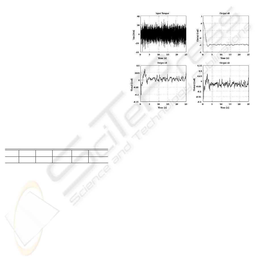
Firstly, experimental works were carried out for
the parallel inverted pendulum system with original
parameters using the control system designed for its
original parameters. However, none of experiments
succeeded. Then, experimental works using the con-
trol system designed for obtained optimal parameters
were executed. Experimental results are shown in
Fig.2.
Figure 2: Experimental Results
As shown in Fig.2, stabilization of both pendulums
are succeeded.
5 VERIFICATION
In order to evaluate the effectiveness of the proposed
control system in terms of structural systems design,
the following experiments were executed. First, fix-
ing the position of center of gravity of one of the
pendulums, several controllers are designed chang-
ing parameters for the position of center of gravity of
another pendulum little by little in controller design.
Then, for each controller, experimental works for sta-
bilization control were carried out by shifting the real
position of center of gravity of the pendulum in actual
system little by little.
Experimental results for fixing l
c2
=0.0725 and
changing conditions of l
c1
are shown in Table 2. On
the other hands, experimental results for fixing l
c1
=
0.172 and changing conditions of l
c2
are shown in Ta-
ble 3.
From Table 2 and Table 3, it can be said that
l
c1
=0.172 and l
c2
=0.0725 are the robustest value
of the center of gravity for pendulums in both aspects
ICINCO 2004 - SIGNAL PROCESSING, SYSTEMS MODELING AND CONTROL
112

Table 2: Changing l
c1
with l
c2
=0.0725 (fixed)
0.180 0.178 0.176 0.174 0.172 0.170
0.180 × × × × × ×
0.178 × × × × × ×
0.176 × ×
0.174 ×
0.172
0.170
Row : Real position of center of gravity
Column : Parameter used to design controller
×: Failure, : Success (Good), : Success (Very good)
Table 3: Changing l
c2
with l
c1
=0.172 (fixed)
0.0825 0.080 0.0775 0.075 0.0725 0.070
0.0825 × × × × × ×
0.0800 × × × × × ×
0.0775 × × × × × ×
0.0750 × × × × ×
0.0725
0.0700 × × × × × ×
Row : Real position of center of gravity
Column : Parameter used to design controller
×: Failure, : Success (Good), : Success (Very good)
of structural and control systems. In terms of above
observations, we conclude that the effectiveness of the
proposed integrated design of structure/controller for
parallel inverted pendulum systems was verified.
6 CONCLUSIONS
In this paper, we proposed an integrated design of
structure/controller for parallel inverted pendulum
systems, in which the position of center of gravity
of the pendulums are set as structural parameters in
structural systems, and state feedback gain and struc-
tural parameters are determined based on a design of
linear quadratic regulator(LQR). There are two fea-
tures in the proposed method. The first one is that a
descriptor form representation is used to express the
dynamics of parallel inverted pendulum systems in or-
der to show the structural parameters linearly. The
second one is that a generalized Ricatti equation in
LQR problem for the descriptor form representation
is finally reduced to LMI conditions. To the best of
our knowledge, this is the first paper which gives the
position of center of gravity of pendulums for paral-
lel inverted pendulum systems analytically in a sense
of suitable for control. Based on the obtained struc-
tural parameters, we executed experimental works for
stabilization. Experimental works show the effective-
ness of the proposed design method.
REFERENCES
Hale, A. L., Lisowski, R. J., & Dahi, W. E. (1985). Optimal
Simultaneou Structure and Control Design of Maneu-
vering Flexible Spacecraft.
Journal of Guidance, Con-
trol and Dynamics, 8-1
, 86-93.
Pil, A. C., & Asada, H. H. (1996). Integrated Struc-
ture/Control Design of Mechatronic Systems Us-
ing a Recursive Experimental Optimization Method.
IEEE/ASME Transactions on Mechatronics, 1-3
, 191-
203.
Seto, K., Kajiwara, I., Nagamatsu, A, & Morifuji, H.
(1989). Design of an Optical Servosystem using a
Structural Optimizing Method with a Control Sys-
tem by way of Vibration.
Journal of JASM-C, 55-516
,
2029-2036. (in Japanese)
Ando, H., Obinata, G., & Miyagaki, J. (2003). Integrated
Design of Structure/Controller for Track-Following.
Proceedings of the 8th Symposium on Motion and Vi-
bration Control
, 146-151. (in Japanese)
Kim, J. H., Shimomura, T., & Okubo, H. (2003). Simul-
taneous Optimal Design of Structural/Control Sys-
tems (An Approach via Successive LMI Optimiza-
tion).
Proceedings of the 8th Symposium on Motion
and Vibration Control
, 154-157. (in Japanese)
Kawatani, R., & Yamaguchi, T. (1993). Analysis and Stabi-
lization of a Parallel-Type Double Inverted Pendulum
System.
Journal of SICE, 29-5
, 572-580. (in Japanese)
Sugie, T., & Okada, M. (1993). H
∞
Control of a Parallel
Inverted Pendulum System.
Journal of ISCIE, 6-12
,
543-551. (in Japanese)
Simomura, T., & Fujii, T. (1993). A Iterative Method
for Mixed H
2
/H
∞
Control Design with Uncom-
mon LMI Solutions.
Proceedings of American Con-
trol Conference
, 3292-3296.
INTEGRATED DESIGN OF STRUCTURE/CONTROLLER FOR PARALLEL INVERTED PENDULUM SYSTEMS
113
