
A DSP-BASED ACTIVE CONTOUR MODEL
Juan Zapata
Depto. de Electr
´
onica, Tecnolog
´
ıa de Computadoras y Proyectos.Universidad Polit
´
ecnica de Cartagena.
Campus Muralla del Mar s/n. Cartagena, Spain
Ram
´
on Ruiz
Depto. de Electr
´
onica, Tecnolog
´
ıa de Computadoras y Proyectos.Universidad Polit
´
ecnica de Cartagena.
Campus Muralla del Mar s/n. Cartagena, Spain
Keywords:
Ultrasound image processing, DSP processors, active deformable contours.
Abstract:
In this paper a DSP-based active contour model for tracking of the endocardium in a sequence of echocar-
diographic images is presented. If a contour is available in the first frame of a sequence, the contours in the
subsequent frames are segmented. Deformable active contours is a technique that combine geometry, physics
and approximation theory in order to solve problems of fundamental importance to medical image analysis;
such as segmentation, representation and matching of shapes, and the tracking of objects in movement. The
procedure has been developed on a DSP processor using its hardware features. The results are illustrated using
a sequence of four-chambers apical echocardiographic images.
1 INTRODUCTION
In recent years, ultrasound image processing has at-
tracted the attention of researchers in the study of
diagnostic systems based on the analysis of images,
mainly due to the non-ionizing nature of ultrasonic ra-
diation and the consequent reduction of risks for the
patient and the medical professional. In this respect,
it can be confirmed that some aspects of techniques
used in the analysis of images have been strongly in-
fluenced by the development of solutions to typical
problems in this domain such as the recognition of
areas with anatomical meaning in the image and non-
rigid movement tracking.
Operations developed for image processing are
computationally intensives, mainly due to the tremen-
dous volume of optical information and the com-
plex mathematical operations required. This aspect
of computational demand becomes decisive when a
real-time result is required. General purpose proces-
sors are not appropriate for real-time medical process-
ing imaging applications because of technical trade-
offs in hardware design. General purpose processors
are extremely capable when it comes to data manip-
ulation but are inefficients for mathematical calcula-
tion. DSP (digital signal processing) processors work
in an opposite way since they are efficient for mathe-
matical calculation and less efficients in data manip-
ulation (Lapsley et al., 1996). Digital signal process-
ing is one of the most powerful technologies and has
shown enormous growth and had an important tech-
nological impact in several areas, e.g. in telecommu-
nications, medical imaging, radar and sonar, high fi-
delity music reproduction, to name just a few. DSP
systems are perfectly capable of solving the problem
of endocardium motion tracking in echocardiography
images.
Numerous papers have considered the problem of
automatic contour tracking. One approach is to use
active contour models to track the boundaries of
anatomic structures in medical images. This tech-
nique is a suitable alternative to classic edge-based
segmentation techniques, and combines the detection
of grey level transitions within the image together
with the need to obtain a closed contour. This task
involves both hardware and software aspects. In fact,
while purely hardware solutions have proved to be
inefficient and unsuitable for complex algorithms, a
purely software solution based on a PC does not of-
fer a large bandwidth in terms of MOPS and system
throughput (Geminami et al., 1999). Therefore, an in-
tegrated hardware/software platform based on a DSP
processor located in a host PC was chosen as environ-
ment to develop active contour algorithms. Due to its
full programmability, high performance and novel ar-
chitecture, the TMS320C6701 is one of the most suit-
ables devices for researching and testing new digital
signal processing algorithms.
425
Zapata J. and Ruiz R. (2004).
A DSP-BASED ACTIVE CONTOUR MODEL.
In Proceedings of the First International Conference on Informatics in Control, Automation and Robotics, pages 425-429
DOI: 10.5220/0001135604250429
Copyright
c
SciTePress

2 A CONTOUR TRACKING
ALGORITHM
Geometrically, a snake or deformable active contour
is a spline with a parametric representation v(s) =
(x(s), y(s)) embedded in the image plane (x, y ∈ R),
where x and y are the coordinate function and s ∈
[0, 1] is the parametric domain (Kass et al., 1988). En-
ergetically, the active contour is subordinated to two
types of energy that dictate its behaviour. Equation (1)
can be viewed as a representation of the energy of the
contour and the final shape corresponds to the mini-
mum of this energy.
E
∗
snake
=
Z
1
0
E
int
(v(s)) + E
ext
(v(s)) (1)
The first term of the functional is the internal de-
formation energy. This internal energy (2) consists of
the first and second derivatives of v(s) in relation to s
and characterizes the deformation of a stretchy, flex-
ible contour. Two parametric functions, ω
1
(s) and
ω
2
(s), dictate the simulated physical characteristics
of the tension and rigidity of the contour, respectively.
Z
1
0
E
int
(v(s)) ds =
Z
1
0
ω
1
(s)
¯
¯
¯
¯
∂v(s)
∂s
¯
¯
¯
¯
+ ω
2
(s)
¯
¯
¯
¯
∂
2
v(s)
∂s
¯
¯
¯
¯
2
ds
(2)
The second term, the external energy, also termed the
image energy, couples the snake to the image. Tradi-
tionally,
Z
1
0
E
ext
(v(s)) ds =
Z
1
0
P (v(s)) + E
con
(v(s)) ds
(3)
where P (v(s)) denotes a scalar potential function de-
fined on the image plane. This scalar function can
be designed so that local minima coincide with inten-
sity extrema, edges or other image features of interest.
The second term of the equation (3), E
con
(v(s)), is
the energy consequence of external constraints. These
asserted constraints can benefit certain zones or lo-
cal characteristics of the image. Therefore, during the
minimization procedure, the contour can be favoured
to reach these zones.
There are two key difficulties with the original
technique. First, the procedure requires that the ini-
tial contour lies near the feature of interest and relies
on an inherent force to move the contour towards the
edges. Cohen (Cohen, 1991) decided to include of
a force to oblige the active contour to expand and to
contract in the absence of other type of forces in or-
der to solve some of the problems encountered in the
original model, where main problem was that a snake
which is not close enough to the edges or interest fea-
tures is not attracted by them, and so the object con-
tour is reached very slowly or converges to a straight
line. The model developed by Cohen allows a be-
haviour like a balloon since the curve is driven by an
internal pressure force. In summary, our model pro-
poses to use this pressure force in order to allow a
faster approximation of an active contour when it is
not near the real contours of the object to segment.
Cohen formulates the balloon model in the following
form: F = k
1
~n(s) − k
∇P
||∇P ||
, where ~n(s) is a nor-
mal unitary vector to the curve at point v(s), k
1
is the
force amplitude and k a scale factor and P is the im-
age potential. Other methods have been proposed to
solve the problem of initialization (Leroy et al., 1996;
Cohen and Cohen, 1993). The main idea, common
in others techniques too, is to increment the capture
range of the external forces and to guide the initial
contour towards the desired contour.
A second problem appears when the active contour
cannot progress in the concavities of the object (Da-
vatzikos and Prince, 1995). There is no success-
full solution to this problem, although several forces
have been proposed by researchers (Cohen, 1991; Da-
vatzikos and Prince, 1995; Davatzikos and Prince,
1994; Prince and Xu, 1996). However, although
many of these proposed methods solve theproblem
they given rise to new difficulties. For example, pres-
sure forces must be initialized to push out or push in,
a condition that involves careful initialization. Xu and
Prince designed a new external force called gradient
vector flow force or GVF force (Xu and Prince, 1997;
Xu and Prince, 1998); which is intended to solve the
aforementioned problems. The gradient vector flow
field is a vectorial field which is derived from the
image through the minimization of an energy func-
tional. This external GVF force is computed as a dif-
fusion of the gradient vectors of a gray-level or binary
edge map derived from the image. The GVF field can
be found by solving the following Euler equations,
where ∇
2
is the Laplacian operator:
µ∇
2
u − (u − f
x
)(f
2
x
+ f
2
y
) = 0 (4)
µ∇
2
v − (v − f
x
)(f
2
y
+ f
2
y
) = 0 (5)
Equations (4) and (5) can be rewritten as follows:
u
t
(x, y, t) =
µ∇
2
u(x, y, t) − b(x, y)u(x, y, t) + c
1
(x, y)
v
t
(x, y, t) =
µ∇
2
v(x, y, t) − b(x, y)v(x, y, t) + c
2
(x, y)
(6)
where:
b(x, y) = f
x
(x, y)
2
+ f
y
(x, y)
2
(7)
c
1
(x, y) = b(x, y)f
x
(x, y) (8)
c
2
(x, y) = b(x, y)f
y
(x, y) (9)
We have introduced a hybrid energy term (S
´
anchez
et al., 2000), which is an adaptive combination of both
ICINCO 2004 - ROBOTICS AND AUTOMATION
426

terms, GVF and balloon energy. In this way, if there is
no GVF field, then the balloon force acts on the active
contour, although its influence over the active contour
decreases as the GVF force increases in magnitude.
The superposition of effects get through the balloon
force and the GVF force is ruled by a user parame-
ter. The optimum value of this parameter is obtained
when the influence of the pressure force over the ac-
tive contour is null.
3 HARDWARE OVERVIEW
3.1 TMS320C60 EVM evaluation
board
The choice of DSP-based hardware permits the de-
velopment of a powerful and highly flexible sys-
tem. Due to its full programmability and high per-
formance, the TMS320C6701 processor mounted on
the TMS320C60 EVM is a suitable device for re-
searching and testing DSP algorithms. In the work
described in this paper, a personal computer was
equipped with the Code Composer Studio develop-
ment environment which helps to construct and debug
embedded real-time DSP applications. It provides
tools for configuring, building, debugging, tracing
and analyzing programs. Texas Instruments DSP’s
provide on-chip emulation support that enables Code
Composer Studio to control program execution and
monitor real-time program activity. The heart of the
TMS320C60 EVM evaluation board is the Texas In-
struments TMS320C6701 processor. The C6701 is
based on a VLIW-like architecture which allows it to
execute up to eight RISC-like instructions per clock
cycle.
The two data paths of the C6701 extend the func-
tionality of the data paths of the C6201 with support
for 64-bit data and IEEE-754 32-bit single-precision
and 64-bit double-precision floating-point arithmetic.
Each data path includes a set of four execution units,
a general-purpose register file, and paths for moving
data between memory and registers. The four exe-
cution units in each data path comprise two ALUs,
a multiplier and an adder/subtractor which is used
for address generation. The ALUs support both in-
teger and floating point operations, and the multipli-
ers can perform both 16x16-bit and 32x32-bit integer
multiplies and 32-bit and 64-bit floating point mul-
tiplies. The two register files each contain sixteen
32-bit general-purpose registers. To support 64-bit
floating point arithmetic, pairs of adjacent registers
can be used to hold 64-bit data. In addition to the
operations supported by the C6201, the C6701 of-
fers support for floating-point reciprocal and recip-
rocal square root estimation, and for converting data
between fixed- and floating-point formats.
3.2 Implementation
Although the code running on the DSP processor can
be written in C because the compiler generates an
quasi-efficient code, the performance of the applica-
tion can be maximized by using compiler options,
intrinsic instructions, and assembly code transforma-
tion. In fact, this previous strategy was used in our
code.
The computational cost of the active contour algo-
rithm constitutes most the computational cost of the
entire procedure. Therefore, the algorithm is imple-
mented in assembly language on the four execution
units in each data path and executed in parallel in or-
der to utilize all the hardware resources of DSP and
exploit all the capabilities of the architecture VLIW
and software pipelining. Because most of the millions
of instructions per second (MIPS) in DSP applications
occur in tight loops, it is important for the application
to make maximal use of all the hardware resources in
important loops. Fortunately, loops have more inher-
ent parallelism than non-looping code because multi-
ple iterations of the same code are executed with lim-
ited dependency between each iteration.
To maximize the efficiency of the code, the ap-
plication schedules as many instruction as possible
in parallel. For this, the relationships, or dependen-
cies, between instructions were determined. Figure 1
shows the assembly instructions for floating-point ac-
tive contour and allocated resources.The symbol || de-
fines which instruction is being executed in parallel,
while the symbol @ defines which iteration of the loop
is executing each cycle. For example, the rightmost
column shows that on during given cycle inside the
loop, the ADDSP instruction is adding data for iter-
ation n, the MPYSP instruction is multiplying data
for iteration n+2 (@@), and so on. No value can live
in a register for more than the number of cycles in
the loop. Otherwise, iteration n+1 writes into reg-
ister before iteration n has read that register. The
live-too-long problem means that no loop variable can
live longer than the iteration interval, because a child
would then read the parent value for the next itera-
tion. A simple solution is to break up the lifetime of
a variable by inserting move (MV) instructions in or-
der to break up the path of the variables into smaller
pieces and can live for minimum iteration interval.
One way to accomplish if-then-else in assembly code
is by means of conditional instructions in one of the
five general-purpose registers. Conditional instruc-
tions can handle both the true and false cases of if-
then-else statement. Branching is one way, although,
because each branch has five delay slots, this method
requires additional cycles. Furthermore, branching
A DSP-BASED ACTIVE CONTOUR MODEL
427

within the loop makes software pipelining almost im-
possible. Using conditional instructions eliminates
the need to branch to the appropriate piece of code af-
ter checking the condition. For this, instructions can
be used on the zero and nonzero values of a condition
register. This method also allows software pipeline
the loop and achieve much better performance.
4 RESULTS AND DISCUSSION
The high speed contour tracking procedure was tested
on sequences of cardiovascular images. The video
was captured with a resolution of 512x512 pixels, 8
bits per pixel, 25 frames per second.
The procedure, designed to track the endocardial
walls, used a hybrid snake to segment the first frame
of the ultrasound sequence (see Figure 4). In the
next frames, the active contour is located under the
GVF force derived from a GVF field of reduced dif-
fusion. A GVF field of reduced diffusion cannot close
all the discontinuities, and so if the pressure force is
found in any place of the image, it may deform the
contour further of endocardial boundaries or invade
other chambers. In this case, it is necessary to de-
activate the force although there is no GVF field. In
this way, the GVF snake (very close to its real con-
tour) is only influenced by the rest of the concerned
forces and deformations are not produced. Our exper-
iments are based on tracking each chamber in differ-
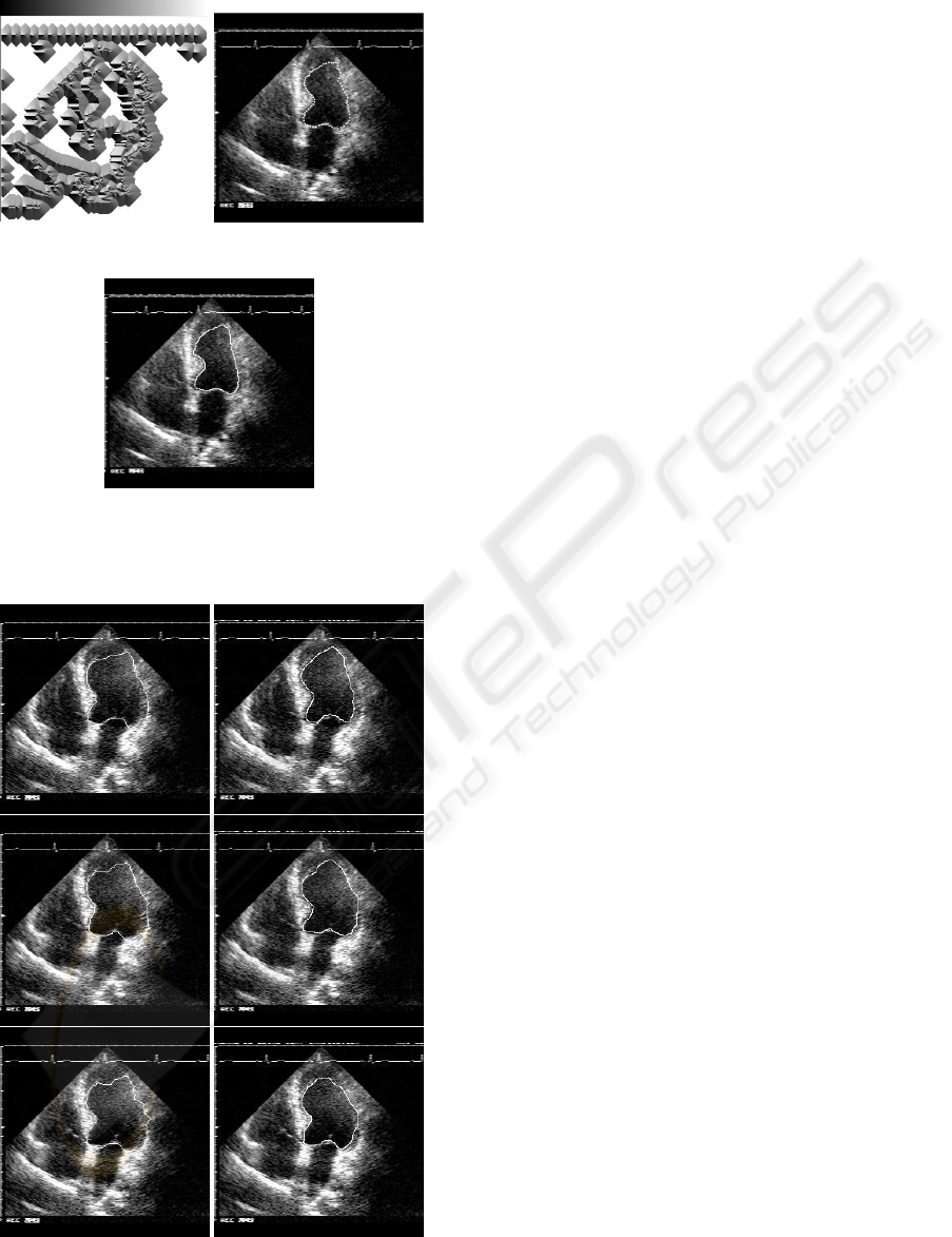
ent echocardiographic sequences. In summary, Fig-
ure 3 shows the echocardiographic sequence for the
left ventricle (three frames are shown), with the ac-
tive contours achieved in the first column and drawn
by a specialist in the second column. The similar-
ity is about a 94.5% for the first and second frame
and a 94.7% for the third frame. Similar results were
achieved for different frames of the sequence and for
the others chambers.
The software was implemented and configured to
process instructions in parallel. To be more exact,
loop kernel can be executed in 7 cycles only. Ev-
ery execution packet involves at least two instructions
executing in parallel, although there are packets with
five instruction in parallel and an execute packet with
seven instruction in parallel. Therefore, if we sup-
pose our snake has 80 snaxels then the energy of a
neighboring point is calculated in each iteration (7
cycles). Each snaxel has 9 neighbours and, therefore,
80×9×7 = 5040 cycles are needed for the active con-
tour in a frame. In a complete sequence, in one sec-
ond, 5040 × 25 = 125.800 cycles are needed and the
DSP load is just 0.1% (125K/160M × 100). Given
these circumstances, the implementation can be con-
sidered very satisfactory for the DSP adopted.
We have presented a high-speed contour tracking
;** --------------------------------------*
L3: ; PIPED LOOP KERNEL
ADDSP .L2 B4,B7,B4 ; |27|
|| MV .S2X A5,B4 ; twin reg.
|| MV .L1 A6,A0 ; @@long l.
|| [ A1] LDW .D2T2 *B5,B6 ; @@|27|
|| [ A1] LDW .D1T1 *A0,A5 ; @@|27|
[ B0] B .S2 L3 ; |29|
|| SUBSP .L1 A10,A5,A4 ; @|27|
|| SUBSP .L2X B8,A5,B4 ; @|27|
|| [ A1] LDW .D1T2 *A3,B5 ; @@|27|
|| MV .S1 A7,A6 ; @@@longl.
ADDSP .L2X A4,B4,B7 ; |27|
|| ADDSP .L1 A7,A11,A5 ; @@@@|27|
[ A1] SUB .D1 A1,1,A1 ;
|| SUBSP .L2X B6,A3,B7 ; @|27|
|| SUBSP .L1 A10,A4,A5 ; @|27|
|| SHL .S1 A5,3,A3 ; @@@|27|
[!B2] STW .D2T2 B4,*++B9(12); |27|
|| MPYSP .M1 A14,A0,A5 ; @@|27|
|| ADDAW .D1 A3,A5,A3 ; @@@|27|
|| ADD .S1 1,A9,A9 ; @@@@|29|
[ B0] SUB .S2 B0,1,B0 ; @|29|
|| MPYSP .M1 A0,A5,A3 ; @@|27|
|| ADD .S1 A2,A3,A3 ; @@@
|| ADD .D1 A12,A3,A13 ; @@@
|| INTSP .L1 A9,A7 ; @@@@@|27|
[ B2] MPYSU .M2 2,B2,B2 ;
|| [!B2] STW .D2T2 B7,*+B9(4) ; |27|
|| MPYSP .M1X A0,B5,A4 ; @@|27|
|| ADD .S2X B1,A13,B5 ; @@@|27|
|| ADD .S1 A8,A13,A0 ; @@@|27|
|| ADD .D1 A8,A3,A3 ; @@@|27|
|| SPTRUNC .L1 A5,A5 ; @@@@|27|
Figure 1: Loop kernel for the active energy algorithm
ICINCO 2004 - ROBOTICS AND AUTOMATION
428
0 359
(a) GVF field of reduced
diffusion
(b) Hybrid snake
(c) Boundary proposed by
a expert human
Figure 2: Left ventricle boundary delimitation
Figure 3: Tracking of the left ventricle in a sequence of
ultrasound images.
procedure where a snake is used to contour the endo-
cardium in a sequence of echocadiographic images.
Our preliminary results are encouraging. The main
effort consists in the development of a user interface.
This interface must communicate the host with the ap-
plication running on the DSP, must initialize the active
contour and set up the tuning parameters. Our sys-
tem should be tested with other echographic images
to measure its real performance and tuning capacity.
REFERENCES
Cohen, L. (1991). On Active Contour Models and Balloons.
Computer Vision, Graphics and Image Proccessing,
53(2):211–218.
Cohen, L. and Cohen, I. (1993). Finite-Element Methods
for Active Contour Models and Balloons for 2-D and
3-D Images. IEEE Trans. Pattern Analysis and Ma-
chine Intelligence, 15(11):1131–1147.
Davatzikos, C. and Prince, J. L. (1994). Convexity Analysis
of Active Contour Models. In Proc. Conf. on Info. Sci.
and Sys., pages 581–587.
Davatzikos, C. and Prince, J. L. (1995). An Active Con-
tour Model for Mapping the Cortex. IEEE Trans. on
Medical Imaging, 14(1):65–80.
Geminami, V., Provvedi, S., Demi, M., Paterni, M., and
Benassi, A. (1999). A DSP-Based Real Time Contour
Tracking System. IEEE.
Kass, M., Witkin, A., and Terzopoulos, D. (1988). Snakes:
Active Contour Models. International Journal of
Computer Vision, 1(4):321–331.
Lapsley, P., Bier, J., Shoham, A., and Lee, E. (1996). DSP
Processor Fundamentals: Architectures and Features.
IEEE Press.
Leroy, B., Herlin, I., and Cohen, L. D. (1996). Multi-
resolution Algortihms for Active Contour Model. In
12th International Conference on Analysis and Opti-
mization of System, pages 58–65.
Prince, J. and Xu, C. (1996). A New External Force Model
for Snakes. In 1996 Image and Multidimensional Sig-
nal Processing Workshop, pages 30–31.
S
´
anchez, P. J., Zapata, J., and Ruiz, R. (2000). An ac-
tive contour model algorithm for tracking endocardiac
boundaries in echocardiographic sequences. Criticals
Reviews in Biomedical Engineering.
Xu, C. and Prince, J. (1997). Gradient Vector Flow: A New
External Force for Snakes. In IEEE Proc. Conf. on
Comp. Vis. Patt. Recog. (CVPR), pages 66–71.
Xu, C. and Prince, J. (1998). Snakes, Shapes, and Gradient
Vector Flow. IEEE Transactions on Image Process-
ing, pages 359–369. March.
A DSP-BASED ACTIVE CONTOUR MODEL
429
