
TOWARDS A CONCEPTUAL FRAMEWORK-BASED
ARCHITECTURE FOR UNMANNED SYSTEMS
Norbert Oswald
European Aeronautic Defence and Space Company - EADS,
Military Aircraft, 81663 Munich, Germany
Keywords:
Software architecture, autonomous system, modelling
Abstract:
Future unmanned aerial systems demand capabilities to perform missions automatically to the greatest possi-
ble extent. Missions like reconnaissance, surveillance, combat, or SEAD usually consist of recurring phases
and contain resembling or identical portions such as autonomous flight control, sensor processing, data trans-
mission, communication or emergency procedures. To avoid implementing many similar singular solutions,
a systematic approach for the design of an unmanned avionic software architecture is needed. Current ap-
proaches focus on a coarse system design, do not integrate off-the-shelf middleware, and do not consider the
needs for having on-board intelligence.
This paper presents a reference software architecture to design and implement typical missions of unmanned
aerial vehicles based on a CORBA middleware. The architecture is composed of identical components and
rests upon the peer-to-peer architectural style. It describes the internal structure of a single component with re-
spect to autonomous requirements and provides a framework for the rapid development and implementation of
new components. The framework separates functionality and middleware by hiding ORB specific statements
from components. Experimental tests simulating a reconnaissance mission using various ORB implementa-
tions indicate the benefits of having an architectural design supporting multi-lingual multi-process distributed
applications.
1 INTRODUCTION
As a result of technological advances in many dis-
ciplines like flight control, data and signal process-
ing, sensor engineering, communication links, and
integrated modular avionics, the development of un-
manned aerial systems is currently of great interest
in the domain of military aircrafts. Such systems
raise the possibility to conduct military operations in
a more efficient and less risky fashion than before but
require robustness and reliability. Because of its dy-
namic, stochastic, and largely unknown environment,
the execution of missions needs software systems that
are able to act autonomously especially in situations
were no remote control is possible.
Missions like reconnaissance, surveillance, com-
bat, suppression of enemy air defence, or air-to-air
contain a number of components that can be recycled.
From the software point of view a mission typically
consists of a mission independent and a mission de-
pendent part. Tasks of the mission independent part
like takeoff, landing, or autonomous flight recur for
various missions. But also in the independent part re-
sembling or identical portions such as data transmis-
sion, communication or emergency procedures occur.
This suggests to design and build a unique software
architecture facilitating to cover demands of most
missions. To do so, one has to incorporate features
of today’s avionic systems. Characteristic for avionic
applications are their heterogeneous and distributed
environment with various platforms as well as exist-
ing and approved multi-lingual legacy code. As re-
design, porting and testing of software to new plat-
forms is costly and time-consuming, one needs a soft-
ware architecture that integrates existing code written
for particular platforms, in various languages, for dif-
ferent operating systems as well as COTS products.
Desirable would be an open platform that enables dis-
tributed computing, dynamic algorithm plug-in, and a
rapid algorithm switching, also incorporating aspects
such as real-time, fault tolerance and security.
When dealing with the development of such a soft-
ware architecture one has to consider the work done
so far from three subject areas, the military sector, the
118
Oswald N. (2004).
TOWARDS A CONCEPTUAL FRAMEWORK- BASED ARCHITECTURE FOR UNMANNED SYSTEMS.
In Proceedings of the First International Conference on Informatics in Control, Automation and Robotics, pages 118-126
DOI: 10.5220/0001137501180126
Copyright
c
SciTePress

artificial intelligence community and the field of ar-
chitecture description languages (ADL). In the mili-
tary sector, there is still a primary focus on the de-
sign of physical platforms, low-level control systems
and sensing. Recently, there has been some work
started in order to build so-called open source plat-
forms. OCP is a joint venture from Boeing, Georgia
Institute of Technologies and Honeywell Laboratories
to build an open control platform designed to give fu-
ture UAVs more capable flight control systems and in-
tegrates interdisciplinary systems that enables recon-
figurable control (Schrage and Vachtsevanos, 1999)
(Wills et al., 2001). A prototype of OCP was lately
tested on a UAV helicopter. JAUS is another example
of a joint venture to design an architecture for future
unmanned systems. The main focus of this project
is based upon building an architecture for various
unmanned systems that tries to become independent
from technological trends (JAUS, 2004) (Hansen,
2003). A third initiative is the avionics architecture
description language (AADL) which is expected to
pass as a standard soon. The AADL has be designed
to support a model-based architecture-driven devel-
opment of large-scale systems with an emphasis on
concepts that address performance-critical embedded
systems concerns like timing and performance (Feiler
et al., 2003) (Dissaux, 2004).
Building of software architectures has a long tradi-
tion in the artificial intelligence community. The first
important developments go back to the early 80s with
the deliberative architectures from (Nilsson, 1980)
that are characterised through predictable and prede-
termined communication between layers. Reactive
behaviour-based architectures introduced by (Brooks,
1986) that emphasised parallelism over hierarchy ap-
peared later. Intelligent behaviour in such an archi-
tecture emerges from the interactions of multiple be-
haviours and the real world. To combine the bene-
fits of both approaches and thus enabling reactive be-
haviour and planning capabilities a multitude of hy-
brid architectures have been introduced over the in-
tervening years. An overview about various architec-
tures in AI applications can be found e.g. in (Ko-
rtenkamp et al., 1998). Currently, distributed agent
architectures are under investigation. A sample ar-
chitecture is the Open Agent Architecture, a domain-
independent framework for integrating heterogeneous
agents in a distributed environment based on the inter-
agent communication language (Cheyer and Martin,
2001).
Architecture description languages have become an
area of intense research in the software engineering
community. They define software architectures as
reusable and transferable abstractions of software sys-
tems (Clements et al., 2002), composed of compo-
nents, connectors, and configurations to define locus,
interaction, and topology (Garlan and Shaw, 1993).
In general, software architectures are used to describe
the structure of software systems. Support exists from
a number of architectural description languages like
Adage (Coglianese and Szymanski, 1993), C2 (Med-
vidoc et al., 1996) (Medvidoc, 1999), Meta-H (Binns
and Vestal, 1993), or ACME (Garlan et al., 2000) to
name but a few. xADL, another ADL, has been eval-
uated by a number of projects like AWACS aircraft
software system or Mission Data System (Dashofy
et al., 2002). It can be used in a flexible manner to
develop new styles and architectures on a coarse de-
scription level, suited even for families of architec-
tures. An extensive comparison of the various de-
scription languages can be found in (Medvidovic and
Taylor, 2000). Although used in a variety of applica-
tions, each ADL has its particular justification but so
far none of them has accomplished as being a stan-
dard.
At present, most of the propagated approaches lack
on the one hand of support for integrating off-the-
shell middleware (Nitto and Rosenblum, 1999) and
consider on the other hand only the design of coarser-
grained architectural elements. Instead of ignoring
the results that practitioners have achieved in the def-
inition of middlewares, the design of a software ar-
chitecture should incorporate both, the benefits of
top-down and bottom-up approaches. Some research
concerning the integration of middleware has already
been started (e.g.(Dashofy et al., 1999)).
To build systems with capabilities for self-
dependent acting requires a fine-grained design. This
regards in particular the internal architecture of sin-
gle architectural elements like components or connec-
tors. To support this, the present article describes an
integrated view to the design of a reference software
architecture for the domain of unmanned aerial ve-
hicles regarding coarse-grained and fine-grained as-
pects with respect to autonomous requirements. Com-
ponents are considered as architectural elements that
encapsulate functionality in a blackboard style. That
means, the way of providing a service is of no con-
sideration as long as a reasonable result is returned
and each component therefore possesses mechanisms
to ensure the required quality of service.
2 DESCRIPTION OF THE
SOFTWARE ARCHITECTURE
The reference software architecture is an abstract
model that may be substantiated for a multiplicity of
missions. It consists of identical constructed compo-
nents, so-called autonomous entities (AEs), covering
roles and functionalities, connectors that contain var-
ious ORB middleware implementations, and configu-
rations that describe potential connection structures.
TOWARDS A CONCEPTUAL FRAMEWORK- BASED ARCHITECTURE FOR UNMANNED SYSTEMS
119

The design of the architecture follows a peer-to-
peer approach meaning that peers respectively AEs
may exist independently from each other. A pri-
ori, no defined hierarchies exist, but resulting from
the selected AE during setup inherent hierarchies
might appear. The proposed hybrid architecture com-
bines behaviour-based and functional-based aspects
and thus provides deliberative and reactive system be-
haviour. The proposed architecture assists coopera-
Unmanned System two
Unmanned System one
AE
AE
AE
AEAE
AE
AE AE
AE
AE
AE
AE
Ground Station
AE Autonomous Entity
Figure 1: Design of the software architecture
tion not only between AEs of a single system but also
in a group of unmanned systems. Figure 1 shows the
design and configuration of the software architecture
in a single system as well as in a more complex con-
text, being a part of a compound systems, e.g. with a
ground station and another unmanned system.
2.1 Architectural elements
In the following, the architectural elements are iden-
tified and described at domain level. This is done in a
non-formal way but with respect to standard ADLs.
2.1.1 Components
Components respectively AEs are major ingredients
including the functionalities that sum up to the system
capabilities. They work concurrently, synchronously,
or asynchronously and adopt certain roles according
to the embedded functionality. AEs are identified
through the process of decomposing missions in order
to locate recurring conceptual formulations. At this
level of abstraction, the internal representation of an
AE is up to the blackboard style known from artificial
intelligence technologies. To grant access, AEs pro-
vide fixed interfaces for their services to the general
public. These so-called service interfaces are a gen-
eralisation of their embedded functionality, that is to
say, they contain no explicit implementation details.
At design time, own service interfaces are made
available but the precise implementation of an AE’s
functionality is unknown. Because of that, there ex-
ist no information about possibly required service in-
terfaces from other AEs. Thus, there exist no a pri-
ori knowledge about connections between AEs at this
level.
2.1.2 Connectors
Connectors are used to model the communication be-
tween AEs in ADL. In the above software architec-
ture, the CORBA middleware is separated from the
AEs and embedded into the connectors by hiding all
ORB specific activities. If using exclusively TCP/IP-
based communication, it is possible to join the con-
nectors to constitute a communication network based
on CORBA middleware. To do so with heterogeneous
mediums, some effort to implement pluggable proto-
cols is required (see e.g. (Ryan et al., 2000)). Resolv-
ing known services to the locations of their providing
AEs require either a central component similar to the
yellow pages or numerous communications between
AEs performing sophisticated protocols. In terms of
efficiency, a Service Broker is used that manages the
connectors by resolving their requests and keeping
their services and thus assists a component to find a
particular service in the network. An AE accesses a
service simply by calling connect(name). The con-
nector forwards this call to the Service Broker which
resolves the request and returns a CORBA object. The
latter is narrowed by the connector and returned to the
client in form of a usual object reference. This proce-
dure applies too for the access of service interfaces
beyond the particular system.
2.1.3 Configuration
The configuration is used to describe how a system is
built-up. As a consequence of using the framework
that hides the middleware, the coupling between AEs
and connectors during design time requires only one
identical interface, namely connect(name) with name
specifying the name of the service interface. Thus, an
explicit modelling of the relationship between AEs
and connectors is reduced to a single recurring de-
scription.
As a matter of fact, a linking between AEs occurs
through claiming of general public service interfaces.
A concrete configuration will be chosen only at the
beginning of a session. An operator selects from a set
of available AEs the one, that provide the required
mission functionality. The connection structure for
the concrete mission emerges not until the system was
instantiated. Nevertheless, dynamically added AEs
to the running system may be integrated into the con-
nection structure if a dependency to functionalities of
other AEs exists.
ICINCO 2004 - ROBOTICS AND AUTOMATION
120
2.2 Middleware-based framework
Off-the-shelf middleware provides useful mecha-
nisms to enable communication among several pos-
sibly distributed components together with a number
of services like transactional communication or event-
based interactions. In order to use these benefits with-
out having dependencies onto the chosen middleware,
a framework was developed, that encapsulates ORB
specific functionality into the connectors. Essential
elements in the framework are the structure of ser-
vices and the Service Broker.
2.2.1 Structure of a service
Basic element of the architecture is the service, as
communication between AE is mainly based upon
the use of services. Services are defined by IDL
interfaces describing how to access a particular func-
<component name="Navigator">
<interfaces>
<implements>
<type>IDL:AE
navigatorI/INavigator</type>
<optional>
<parameter name="Planner">
<type>IDL:AE navigator/IPlanner</type>
</parameter>
<parameter name="Time limit"></parameter>
</optional>
<attribute name="latency" value="100" />
</implements>
</interfaces>
<dependencies>
<depends>IDL:AE flightControllerI/IFlightController
</depends>
</dependencies>
<subcomponents>
<subcomponent>IDL:AE navigator/IPlanner</subcomponent>
</subcomponents>
</component>
Figure 2: Describing a service to an AE
tionality. To access a service, the name of the ser-
vice interface has to be known. At run-time, an AE
must know about the service interface it provides and
about the service interfaces it requires. These infor-
mations are covered in XML notation for each AE.
Figure 2 shows a sample description of the service in-
terface INavigator provided by the component Navi-
gator. The implements tag indicates that INavigator is
the service interface of the AE. In order to be able to
provide a service, an AE may depend upon additional
service providers. Such dependencies are tagged by
dependencies. In the above example, the AE needs
optionally an implementation for the interface IPlan-
ner and depends on an AE that provides the service
interface IFlightController.
To separate implementation details from the defini-
tion of the service interface, a service uses only a sin-
gle parameter of type string. That means, the imple-
mentation part is hidden in a textual context, needing
a description on how to interpret it. The parameters
can be required or optional like Planner, and inform
clients of which information they need to provide in
order to use the service. The parameters may just
be simple data or they may be complete object ref-
erences. Attributes tell the client something about the
properties of a service. For example, a service may
have a latency attribute which tells the client how slow
to respond the service is likely to be. This allows the
client to make an intelligent selection from the avail-
able services and the best to be chosen. All the at-
tributes and parameters that might be requested by a
service are predifined in the component definition file
in order to maintain consistent semantics.
2.2.2 Service Broker
The Service Broker enables the access to a partic-
ular service. It’s functionality is similar to the one
the Broker Pattern described in (Douglass, 2002) pro-
vides. The Service Broker fulfils two roles: firstly,
that of a name server. It allows service interfaces to
be mapped to a predefined name, which is known to
other components in the system at design-time. This
name can then be resolved to a concrete object refer-
ence, allowing components to find each other at run-
time. Secondly, the Service Broker allows compo-
nent to be registered by the interfaces they implement.
For each interface, the Service Broker maintains a list
of references to components currently running on the
network which implement the interface. Other com-
ponents can query the Service Broker to find this list.
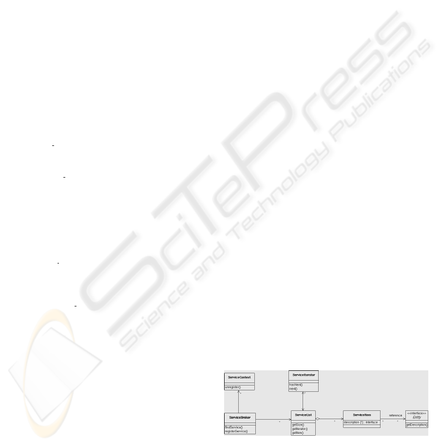
Figure 3 shows the class diagram for the Service
Broker. Each time a new component starts it registers
with the Service Broker and submits a service descrip-
tion of itself by calling addService(). This description
complies with the XML notation of figure 2. When an
Figure 3: Service Broker
AE needs to find a service provider with a particular
service interface, it asks the Service Broker by call-
ing connect(INavigator), which in that case returns a
TOWARDS A CONCEPTUAL FRAMEWORK- BASED ARCHITECTURE FOR UNMANNED SYSTEMS
121

reference to the component that provides INavigator.
Establishing a connection is a task of the connector
for which the latter calls findService(). Because the
Service Broker possesses a reference to the service
description, the callee receives a description of the re-
quired service interface too.
3 DESIGN OF AN AUTONOMOUS
ENTITY
The coarse-grained design of the architecture is build
from a set of identical AE without specifying their
internal structure. However, the architectural design
of an AE is of major importance with regard to the
building of an unmanned system because that requires
to have autonomous capabilities. While (Maes, 1994)
demands from an autonomous system to be adaptive,
robust and effective, we use a similar interpretation
but with different terms. A component is called to be
an autonomous entity, when the following four major
characteristics are fulfilled. It must be able
• to perceive,
• to plan,
• to decide, and
• to act.
Perceiving and acting are parts of today’s avionics
systems. Some of these systems already include plan-
ning and deciding capabilities without human inter-
vention, but the definitive decision-making process
during a mission is still incumbent upon the pilot. To
automize this in order to build the capability of self-
dependent acting requires to have several executable
options. This means, that instead of using a single
algorithm, an AE should comprise of a set of algo-
rithms that solve the same task. To push that claim,
we distinguish between two kinds of components in
the software architecture. An AE on the one hand
provides autonomous capabilities and builds a visible
brick in the architecture. On the other hand, there are
so-called concrete service provider (CSP ) that quote
implementations of basic functionality. These com-
ponents are encapsulated into single AEs and hidden
to public access.
3.1 Structure of an AE
Robustness and reliability requirements force un-
manned systems to allocate mechanisms that enable
support for deciding and planning tasks. To do so,
we divide an AE into a Head and a Body and distin-
guish between allocating basic functionality and func-
tionality that enable intelligent support. The Body
is responsible for providing the basic functionality of
the AE and thus covers the execution of the function-
ality only. The Head is responsible for building the
AE’s capability to act autonomously and covers plan-
ning, modelling and decision aspects. Both parts of
an AE can be regarded as building blocks, with the
Head being on top of the Body.
3.1.1 The Head
The Head provide means that enables an AE to act
independently. The ability to effectively control the
behaviour of an AE indeed depends on the allocated
functionality for the Head. In case there is no in-
telligent support available for the Head, an AE acts
like a conventional component without any decision,
planning or learning capabilities simply based on the
functionality of the Body. To provide responsibility,
the Head requires of intelligent support that allow for
plausible decisions in dynamic situations. Such a de-
cision support which can be considered as a build-
ing block inside the Head is needed in various cases,
among other things for
1. the selection of algorithms to use,
2. the evaluation of calculated results,
3. the synthesis of results, and
4. the handling of exceptional circumstances.
The first task of the Head is a central one with respect
to administrate a set of CSP s. This exercise occurs
each time when there exists more than one implemen-
tation for a problem. Decisions on what algorithm to
select are required for the Body, the evaluation and
the synthesis. Certainly, one could also select the se-
lection, but for this essay, we assume having loaded
a selection algorithm at design-time. The second task
mentions methods which are required to inspect the
plausibility of calculated results. If provisionally re-
sults appear, the Head has to decide how to proceed
in order to guarantee a service. This might lead to a
change in the selection of the native algorithm, im-
provements of a learning component, an update of
model knowledge, or instructions to other AEs. The
third task regards a situation where several algorithms
work in parallel. To build a result for the client, data
have to be fused in an appropriated way. Therefore,
the Head comprises of a number of CSP s allocat-
ing fusion functionality. Task four is of major impor-
tance to the Head because of the AE’s claim to act
autonomously which requires robustness and reliabil-
ity. The Head has to try all feasibilities like using
several implementations in order to execute a given
task reliable. This task does not consider replication
aspects as these should be hidden to the components
and reside inside the connectors. The above list of
tasks for the Head shows minimum requirements and
may be extended on demand without affecting the ar-
chitecture due to their modular design.
ICINCO 2004 - ROBOTICS AND AUTOMATION
122
3.1.2 The Body
The task of the Body is to provide the functionality,
that an AE has registered with the Service Broker.
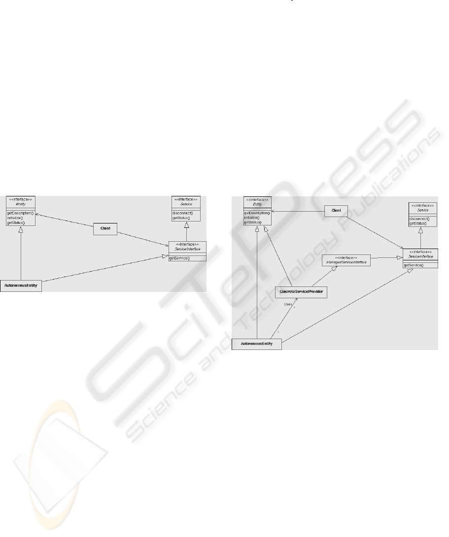
Therefore, the Body implements the propagated ser-
vice interface according to figure 4. The service in-
terface ServiceInterface is visible to all other AEs.
Usually, the Body core itself contains no service im-
plementations. These are provided from the CSP in-
troduced in 3.2. That means, to solve requests that
belong to the same problem domain, a Body has a
number of CSP s at it’s disposal. This indirect access
to the real implementation offers a number of advan-
tages, it allows
• to administrate several identical sources,
• to group services of the same type, and
• to provide distributed processing.
Figure 4: Provision of a service by an AE
Although the CSP wraps the native interface of
an algorithm to the service interface, the required in-
put parameter may differ. As described in the service
structure 2.2, some of the input parameters are fixed
others are optional, that means they will be collected
at run-time. To meet all requirements, the Body re-
solves all variable parameters needed to run a CSP .
The Body communicates with the Head, when-
ever a decision, an evaluation or a synthesis is re-
quired. Also, the Body may appear in the role of a
client to other AEs, if the current task requires addi-
tional services. That means, the Body communicates
with other Heads until a reference to another service
provider, CSP or Body has been selected.
3.2 Provider of concrete services
While an AE provides services without containing a
concrete implementation, a CSP provides an imple-
mentation of a single algorithm. CSP s are indepen-
dent components of the software architecture that be-
long typically to one particular AE. They can be ac-
cessed only indirectly by accessing an AE’s service
interface.
<component name="AStar">
<interfaces>
<implements>AE navigator/IPlanner</implements>
</interfaces>
</component>
Figure 5: CSP providing a service
Services from CSP are provided according to fig-
ure 6. A CSP provides an implementation of the in-
terface ManagedServiceInterface. The CSP registers
that service interface, which is tagged by implements,
with the Service Broker as well as a description on
how to use that particular algorithm. In the example
of figure 5 the component AStar provides the interface
IPlanner. As ManagedServiceInterface is not a gen-
eral public service interface, it is invisible to all AEs
except the one that depends on that concrete service
marked with the dependency tag.
Figure 6: Provision of a service by an CSP
As already mentioned, there are a number of algo-
rithms in the aeronautics domain, that belong to the
same problem domain. Although they solve the same
task, algorithms differ in their native interface, their
behaviour, or may have different constraints. Import-
ing a native interface from legacy code will usually
not meet the service interface. Thus, the CSP wraps
the native interface of the legacy code to the service
interface.
3.3 Retrieving CSP s
An AE provides neither particular basic functional-
ity nor particular intelligent support and thus requires
of having a number of CSP . Each CSP implements
external functionality that belongs either to the Head
or to the Body. As CSP s are part of an AE the lat-
ter can be considered as an application independent
skeleton or frame that provides, among other things,
TOWARDS A CONCEPTUAL FRAMEWORK- BASED ARCHITECTURE FOR UNMANNED SYSTEMS
123
a mechanism for a purposive access to one or several
CSP s. To do so, we have built the Algorithm Se-
lection pattern shown in figure 7. The scope of this
pattern is to return a list of references to implemen-
tations of algorithms that shall be executed. It con-
stitutes a proposal for the first task of the Head in-
troduced in 3.1.1. The Algorithm Selection pattern is
used both from the Body to find a CSP that provides
the required basic functionality and from the Head
to retrieve CSP s that allocate intelligent support like
evaluation and synthesis.
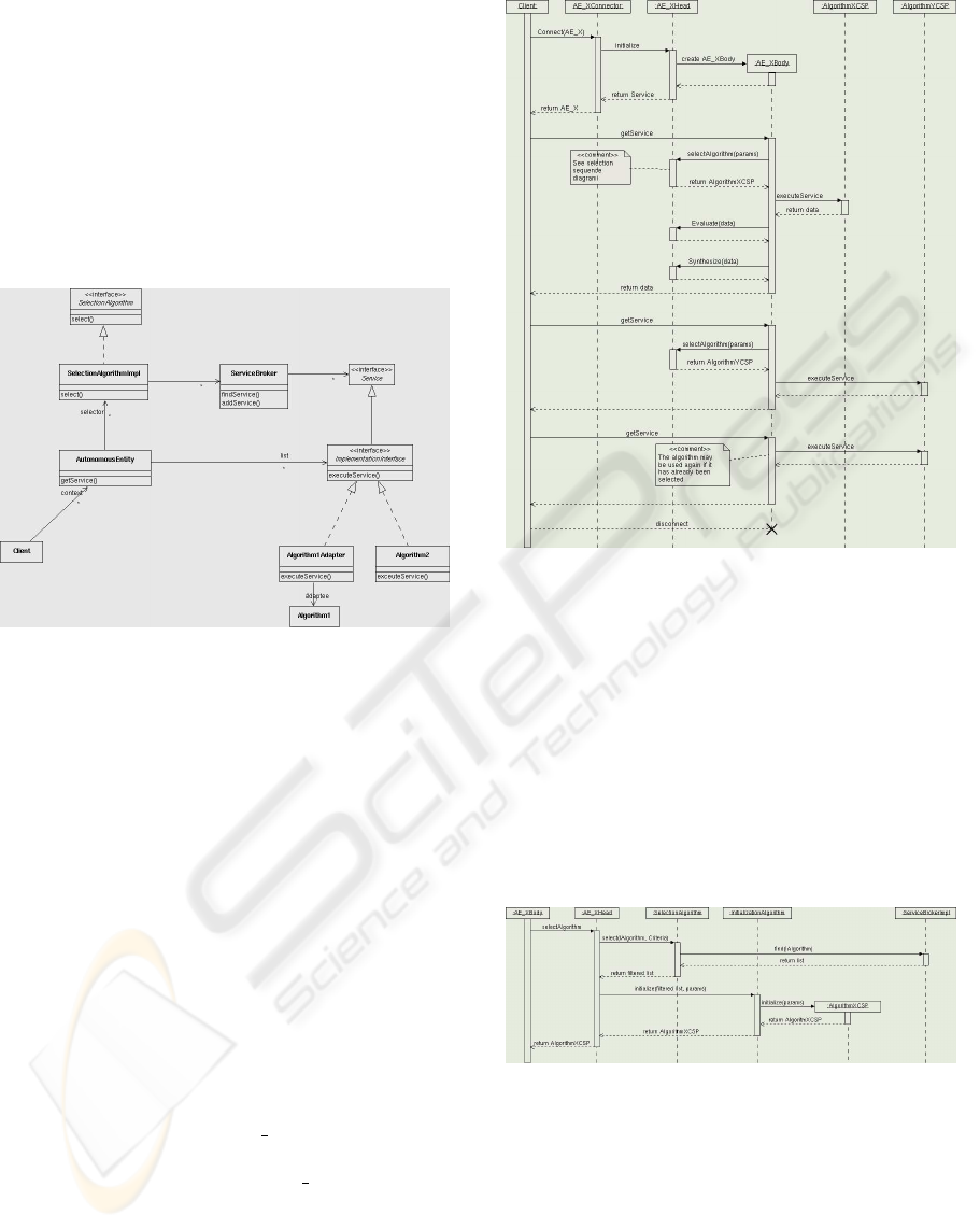
Figure 7: Algorithm Selection pattern
The Algorithm Selection pattern is a collection of
other patterns, namely Factory, Strategy, Adapter, It-
erator and Proxy. It works in the following manner: a
client, either a Head or a Body, tries to resolve refer-
ences for a given task. First, it calls the Service Bro-
ker to return an appropriated list of currently available
CSP s on the net together with their constraints. From
that list, it then decides with the pre-selected decision
algorithm what CSP to use and returns one or several
references.
3.4 Provision of services
After having introduced the construction of an AE,
interactions to provide a service are focused now by
means of the sequence diagram shown in figure 8. An
AE in its role as a client tries to access a particular
service by calling connect(AE X). The connector of
the receiving AE then calls the initialize() method of
the Head of the AE, named as AE XHead in the di-
agram. At that stage, the Head builds a reference to
its Body and returns that reference to the client. The
client now calls the Body directly with one of the pro-
vided service interfaces. When doing that, the Body
either executes directly a pre-selected CSP or it asks
the Head first to select CSP s according to the Algo-
rithm Selection pattern. The result of AlgorithmXCSP
Figure 8: Sequence diagram for service provision
is returned to the Body which calls the Head for eval-
uation. If several results were calculated it might be
required to use a fusion algorithm. The Body asks
the Head to take care of the fusion. In both cases, the
result of these calculations is returned to the Body.
The latter returns the result to the client. For evalu-
ate() and synthesize() the selection of algorithms fol-
lows according to the Algorithm Selection pattern. To
finish a connection or to choose other selection algo-
rithms the client calls disconnect().
Figure 9: Sequence diagram for algorithm selection
The selection of CSP s according to the Algorithm
Selection pattern works as explained in Fig. 9. Af-
ter having received SelectAlgorithm the Head calls
select() to the selection algorithm. There, a findSer-
vice() call is made to the Service Broker. This re-
trieves a list of currently available algorithms respec-
tively CSP s on the net. From that list, the selection
algorithm chooses one or more appropriate CSP s
and return those to the Head. The Head then ini-
ICINCO 2004 - ROBOTICS AND AUTOMATION
124
tialises the chosen CSP s and returns those references
to the Body.
4 EXPERIMENTAL RESULTS
To test the framework we have designed an engineer-
ing platform for autonomous systems (EPAS). This
platform builds the hardware and software infrastruc-
ture to develop, implement and test the behaviour of
constructed software architectures. It consists on the
one hand of a number of different hardware compo-
nents, operating systems and various ORB implemen-
tations. On the other hand, there exists a repository of
Figure 10: Infrastructure provided by EPAS
already constructed AEs and CSP s. Although AEs
in the repository have default settings, they can be
adapted to current mission purposes simply by reas-
signing the set of CSP s for each AE. The status quo
of EPAS is shown in the table of figure 10. In total,
four operating systems, seven ORB implementations
and three languages are supported currently together
with a number of pre-designed AE bricks as well as
two simulators.
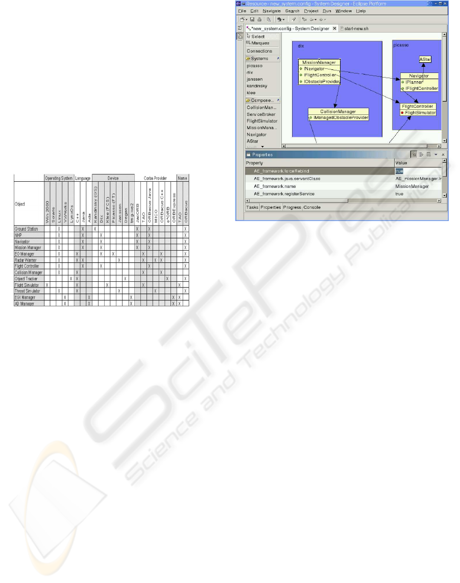
To rapidly construct software architectures, we
have developed a graphical user interface, the so-
called System Designer as shown in figure 11. Ac-
cording to mission requirements, a user selects AE
from the repository shown as boxes in the System De-
signer, or he creates new components. For each AE
the user then assigns the CSP s that resolve the pro-
posed service interfaces. A minimal design is com-
plete when all dependencies are resolved. Currently,
the are no intelligent decision algorithms involved.
Their behaviour is simulated by a simple but flex-
ible decision technique. So far, no system aspects
were considered for the developed software architec-
ture. To do so, the System Designer allows to do a
configuration for each AE and each CSP . Config-
uration parameters include aspects like what ORB to
use and on what machine to run a service. These in-
formations are stored in an XML-based configuration
Figure 11: System Designer
file. From the chosen configuration a start-up script is
build that sets up the whole system. At first, the Ser-
vice Broker is started. Then, components are started
as independent peers without any interactions except
that they register their services with the Service Bro-
ker. So far, there exist no connection structures in the
real application. The resolving of dependencies for an
AE starts with the connect() call. Components check
dependencies on demand and may resolves them by
querying the Service Broker.
5 CONCLUSIONS
We introduced a reference software architecture based
on a component framework to design and implement
typical missions of unmanned aerial vehicles. The
framework separates functionality and middleware by
encapsulating CORBA into connectors and thus sup-
ports, at no expenses for the developer, using the het-
erogeneous avionics environment with various plat-
forms, multi-lingual software, and different operat-
ing systems. Furthermore, the framework provides a
unique architectural skeleton for a single autonomous
entity to meet the requirements for self-dependent act-
ing. A software architecture for a particular mission
emerges from the composition of autonomous entities
covering different functionality and interacting ana-
logue to peers. Advantages of the presented approach
are
• cost saving over a variety of missions because of
reusable design technologies and fast turnaround
TOWARDS A CONCEPTUAL FRAMEWORK- BASED ARCHITECTURE FOR UNMANNED SYSTEMS
125

times,
• reuse of existing and tested software,
• rapid system analysis of the composed mission ar-
chitecture,
• dramatic reduction in mission completion time, and
• using of COTS and open source components.
Experiments in an appropriate engineering platform
for autonomous systems containing various ORB im-
plementations showed the rapid development process
to build and test a software architecture. By means
of a system designer, autonomous entities can be cus-
tomised, combined and distributed at design-time in a
flexible manner.
REFERENCES
Binns, P. and Vestal, S. (1993). Formal real-time archi-
tecture specification and analysis. In In Tenth IEEE
Workshop on Real-Time Operating Systems and Soft-
ware, New York.
Brooks, R. (1986). A layered control system for a mobile
robot. 3rd Symposium. MIT Press, pages 367–372.
Cheyer, A. and Martin, D. (2001). The open agent architec-
ture. Journal of Autonomous Agents and Multi-Agent
Systems, 4(1):143–148. OAA.
Clements, P., Kazman, R., and Klein, M. (2002). Evaluat-
ing software architectures: Methods and case studies.
Technical report, SEI, Series in Software Engineering.
Coglianese, L. and Szymanski, R. (1993). Dssa-adage: An
environment for architecture-based avionics develop-
ment. In AGARD’93.
Dashofy, E., Hoek, A., and Taylor, R. (2002). An infrastruc-
ture for the rapid development of xml-based architec-
ture description languages. In The 24th International
Conference on Software Engineering, Orlando.
Dashofy, E., Medvidoc, N., and Taylor, R. (1999). Us-
ing off-the-shelf middleware to implement connectors
in distributed software architectures. In International
Conference on Software Engineering, Los Angeles.
Dissaux, P. (2004). Using the aadl for mission critical soft-
ware development. In ERTS conference, Toulouse.
Douglass, B. (2002). Real-Time Design Pattern. Addison
Wesley.
Feiler, P., Lewis, B., and Vestal, S. (2003). The sae avion-
ics architecture description language (aadl) standard:
A basis for model-based architecture-driven embed-
ded systems engineering. In RTAS 2003, Washington.
vorhanden.
Garlan, D., Monroe, R., and Wile, D. (2000). Acme: Ar-
chitectural description of component-based systems.
Technical report, CMU, Software Engineering Insti-
tute.
Garlan, D. and Shaw, M. (1993). An introduction to soft-
ware architecture. In Ambriola, V. and Tortora, G., ed-
itors, Advances in Software Engineering and Knowl-
edge Engineering.
Hansen, S. (2003). Integration of autonomous system com-
ponents using the jaus architecture. In AUVSI Un-
manned Systems 2003, Baltimore.
JAUS (2004). Joint architecture for unmanned systems.
http://www.jauswg.org.
Kortenkamp, D., Bonassao, R., and Murphy, R., editors
(1998). Artificial Intelligence and Mobile Robots.
MIT Press.
Maes, P. (1994). Mmodelling adaptive autonomous agents.
Artificial Life, 1(1):135–162.
Medvidoc, N. (1999). Architecture-based Specifi-cation-
Time Software Evolution. PhD thesis, University of
California.
Medvidoc, N., Oreizy, P., Robbins, J., and Taylor, R.
(1996). Using object-oriented typing to support archi-
tectural design in the c2 style. In SIGSOFT’96. ACM
Press.
Medvidovic, N. and Taylor, R. N. (2000). A classifica-
tion and comparison framework for software archi-
tecture description languages. Software Engineering,
26(1):70–93.
Nilsson, N. (1980). Principles of Artificial Intelligence.
Tioga Press.
Nitto, E. D. and Rosenblum, D. (1999). Exploiting ADLs
to specify architectural styles induced by middleware
infrastructures. In Int. Conf. on Software Engineering,
pages 13–22.
Ryan, C., Kuhns, F., Schmidt, D., Othman, O., and Par-
sons, J. (2000). The design and performance of a plug-
gable protocol framework for real-time distributed ob-
ject computing middleware. In ACM/IFIP, editor, Pro-
ceedings of the Middelware 2000 Conference.
Schrage, D. P. and Vachtsevanos, G. (1999). Software en-
abled control for intelligent UAVs. In 1999 IEEE In-
ternational Conference on Control Applications.
Wills, L., Kannan, S., Sanders, S., Guler, M., Heck, B.,
Prasad, J., Schrage, D., and Vachtsevanos, G. (2001).
An open platform for reconfigurable control. IEEE
Control Systems Magazine, 21(3).
ICINCO 2004 - ROBOTICS AND AUTOMATION
126
