
A REAL TIME GESTURE RECOGNITION SYSTEM FOR MOBILE
ROBOTS
Vanderlei Bonato
1
, Adriano K. Sanches
1
, M.M. Fernandes
2
Jo
˜
ao M. P. Cardoso
3
, E. D. V. Simoes
1
, Eduardo Marques
1
1
Institute of Mathematics and Computing Sciences, University of S
˜
ao Paulo
S
˜
ao Carlos, Brasil
2
University Metodista of Piracicaba - UNIMEP; Piracicaba, S
˜
ao Paulo
3
Faculty of Sciences and Technology: University of Algarve
Campus de Gambelas 8000 117; Faro Portugal
Keywords:
Robotics, FPGA, SoC, Vision System, Gesture Recognition, RAM-Based Neural Network.
Abstract:
This paper presents a vision system to be embedded in a mobile robot, both of them implemented using recon-
figurable computing technology. The vision system captures gestures by means of a digital color camera, and
then performs some pre-processing steps in order to use the image as input to a RAM-based neural network.
The set of recognized gestures can be defined using the system on-chip training capabilities. All the above
functionality has been implemented in a single FPGA chip. Experimental results have shown the system to
be robust, with enough performance to meet real-time constraints (30 fps), and also high efficiency in the
recognition process (true recognition rate of 99.57%).
1 INTRODUCTION
Mobile robots have been the central focus of many re-
search works in recent years, dealing with the uncer-
tainty associated with the environment and the data
received via sensors. In this context, machine learn-
ing and probabilistic models are important advances
able to deal with the computational complexity in-
volved (Thrun et al., 2000).
Specialized hardware is an attractive solution to im-
plement robots with real-time constrains. The use of
FPGAs (Field-Programmable Gate Arrays) is a flexi-
ble alternative to implement complex models, as the
hardware functionality can be changed according to
the task to be executed (Oldfield, 1995). It can also
be argued that FPGAs are able to execute image pro-
cessing algorithms with speed comparable to graph-
ics processing custom chips (Zemcik, 2002). How-
ever, designing and programming such a specialized
hardware can still be very complex, which has mo-
tivated us to propose a tool for the design of recon-
figurable robots (Gonc¸alves et al., 2001) (Gonc¸alves
et al., 2003). The approach needs modular hardware
units that are then allocated at the exact time they are
needed. The hardware generated is based on softcores
and special purpose RPUs (Reconfigurable Process-
ing Units), as seen in Figure 1. A softcore is a pro-
cessor core described in a hardware description lan-
guage. The software image to be executed might in-
clude invocations to RPU functionalities. The RPUs
are stored in a library of functional units (RPUs repos-
itory), and can be organized in a way that best suits
a given application. The RPUs can be manually de-
signed hardware units or architectures to implement
specific computational structures, obtained using an
architectural synthesis tool (Cardoso and Neto, 2003).
This paper presents the design and implementation
of an RPU for real time gestures recognition, which
can be used as a human-robot communication inter-
face. By doing so it is possible to interact with a robot
in a non-conventional way, which could be useful in
particular situations (e.g. robots designed to assist
disabled people). This gesture recognition unit will
be incorporated to the tool presented above, and could
be used not only to recognize gestures, but also as a
basis for other applications requiring image patterns
recognition. The structure of the main modules of the
robot currently being developed is shown in Figure 2,
along with the interactions among them. The vision
processing module corresponds to the RPU presented
in this paper.
This paper is organized as follows. Section 2 ex-
207
Bonato V., Sanches A., Fernandes M., Cardoso J., Simoes E. and Marques E. (2004).
A REAL TIME GESTURE RECOGNITION SYSTEM FOR MOBILE ROBOTS.
In Proceedings of the First International Conference on Informatics in Control, Automation and Robotics, pages 207-214
DOI: 10.5220/0001140202070214
Copyright
c
SciTePress
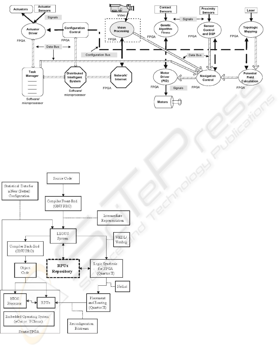
Figure 2: Integration of the vision system into the robot architecture
Figure 1: A tool for robot design
plains the robot vision system and its components.
Section 3 explains the neural network for gesture
recognition, and Section 4 shows the experimental re-
sults obtained. Finally, section 5 concludes this paper.
2 A ROBOT VISION SYSTEM
Computer vision systems for human-robot interaction
have evolved significantly in the past decade. How-
ever, most of them are not robust yet, have low perfor-
mance, and so are not suitable to be used in embed-
ded systems with real time constraints (Turk, 2004).
Most of the previous work in this area delivers the
right functionality (Waldherr et al., 2000), but not as
an embedded device. The system presented in this
paper seeks to address this issue.
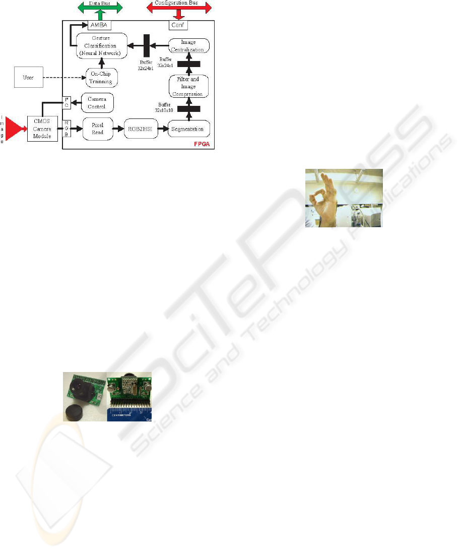
The structure of the vision system is shown in the
blocks diagram of Figure 3. The structure consists of
a pipeline of functional blocks for image processing
operations, which are executed in parallel. The sys-
tem is implemented as a SoC, which allows the ges-
tures recognition system to operate in real time. Each
of those blocks is responsible for an image process-
ing step, such as image capturing, RGB to HSI color
conversion, image segmentation, image filtering and
compression, and finally the centering of the image.
These pre-processing steps are performed prior to the
actual neural network gesture recognition (shown in
section 3).
The integration of the vision system to the robot
is done by means of two communication buses: the
configuration bus, used to configure FPGA structures,
and the data bus used to send the interpreted gestures
to the robot control module.
In the next subsections we describe in more details
ICINCO 2004 - ROBOTICS AND AUTOMATION
208
the image pre-processing steps of the vision system.
Figure 3: Vision system blocks diagram
2.1 Image Capturing
The images used by the gestures recognition system
are captured by a C3188A digital camera, which uses
an ov7620 CMOS image sensor (Electronics, 2004).
This kind of sensor integrates all the functionalities of
a digital camera in a single integrated circuit, allow-
ing for reduced size, low cost, and low power con-
sumption (Rowe, 2002). Those are important param-
eters for the design and implementation of mobile au-
tonomous robots. The camera is able to sustain a rate
of imagens equals to 30 frames per second (fps). The
resolution of gray shade images is 640x480 pixels,
while RGB color images have a resolution of 320x240
pixels. That camera is shown in Figure 4.
Figure 4: CMOS C3188A Camera - 1/3”
The camera configuration is done through the im-
age sensor by using the communication protocol
I
2
C (Philips, 2003). The configuration parameters are
stored in a register set, which can be read or written
through a communication port. Several parameters
can be configured, like fps rate, noise compensation,
and image saturation, among others. In our vision
system the configuration is done via the Camera Con-
trol block (Figure 3).
2.2 Pixels Reading
The data sent by the camera are interpreted by the
Pixel Read block (Figure 3). The data are sent through
a 16-bit bus, containing information about the R,G,
and B values of each pixel, and also synchronization
signals. Based in these, the block reads the pixel and
associates its address to the image.
The R, G, B values and address of each pixel are
then sent to the following block of the system, which
converts the RGB color scheme into HSI. The inter-
pretation of pixels is performed in real time. As an
example, Figure 5 shows an RGB image represent-
ing the ”GO” gesture. This and other images pre-
sented have been generated by the FPGA hardware
implementation described in this paper. In order to
capture those images, an Ethernet based communica-
tion system between the system a PC has been imple-
mented. In addition to capturing images, the interface
also served as a debugging interface.
Figure 5: RGB (320x240 pixels)
2.3 RGB-HSI Conversion
In this operation the Red, Green, and Blue pixel
representation of the RGB scheme are changed into
the corresponding HSI representation, which uses the
Hue, Saturation, and Intensity componentes. This
method is frequently used in image processing sys-
tems because the HSI pixel components are indepen-
dent from each other (as opposed to RGB´s), and so
individual operations can be applied to them (Russ,
1995). In addition, the separation of the I component
makes the image less sensitive to brightness variations
of the working environment.
The RGB-HSI conversion can be considered a
complex operation in this domain (Gonzalez and
Woods, 1992). The complexity of the conversion is
due to a trigonometric function that is required to ob-
tain the H value (Equation 1). The implementation of
that function in FPGAs demands a significant amount
o logical elements to implement the corresponding al-
gorithms. A simplified method to obtain the H com-
ponent from an RGB representation is presented by
Bajon apud Swenson (Swenson, 2002), as shown in
Equation 2. This Equation does not use any trigono-
metric function, and so is simpler to be implemented
in hardware. The I and S components can be obtained
through Equations 3 and 4, respectively, which are
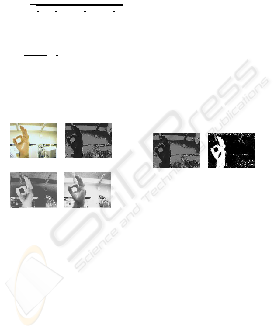
also easily implemented in hardware. Figure 6 shows
the H, S, and I values (gray shades) for an RGB image
obtained with our vision system.
A REAL TIME GESTURE RECOGNITION SYSTEM FOR MOBILE ROBOTS
209
H = cos
−1
2
3
(r −
1
3
) −
1
3
(b −
1
3
) −
1
3
(g −
1
3
)
q
2
3
[(r −
1
3
)
2
+ (b −
1
3
)
2
+ (g −
1
3
)
2
]
(1)
H =
Acromathic if r = g = b
g−b
3(r+g−2b)
if b = min(r, g, b)
b−r
3(g+b−2r)
+
1
3
if r = min(r, g, b)
r−g
3(r+b−2g)
+
2
3
if g = min(r, g, b)
(2)
I =
r + g + b
3
(3)
S = 1 − 3 ∗ min[r, g, b] (4)
(a) RGB (b) H
(c) S (d) I
Figure 6: RGB Image (a), Hue (b), Saturation (c), and In-
tensity (I) ; Resolution: 320x240 pixels
2.4 Image Segmentation
The Segmentation Block is responsible for the trans-
formation of a HSI image into a binary representa-
tion. A number of HSI segmentation techniques have
been proposed, being differentiated basically by the
way each technique relates the H, S, and I components
(ChiZhang, 2000) (Cummings et al., 2003). The vi-
sion system presented in this paper implements two
segmentation techniques, being the first one based on
the value of the H component, and the second one
based on the H, S and I values. Both techniques use
Equation 5, with f(i,j) representing the values of H,
S, or I, and T1,T2 the inferior and superior thresh-
olds, respectively. These ones determine when a pixel
belongs to a region of interest, being constant values
empirically defined. The results of this Equation are
binary values and they are attributed to the f(x,y) po-
sition on the segmented image, that correspond to the
f(i,j) position.
Using the first technique, the result of Equation 5
are the pixels that constitute the segmentated image.
In the second technique, the pixels are obtained from
a logical AND operation applied to the H, S, and I
values resulting from Equation 5. In this work the
best results were obtained by using the first technique,
therefore it is the one that has been adopted. It should
be noticed that the H component depends basically on
the skin color of the user interacting with the robot.
For this reason, gestures are obtained using the inter-
nal part of the hand, as this part of the body has only
small variations in color, which helps to avoid further
system calibrations. The results of a segmentation op-
eration based on the H value is shown in Figure 7.
f(x, y) =
½
1 if [T
1
<= f (i, j) <= T
2
]
0 otherwise
(5)
(a) H (b) Segmented
Figure 7: H Component (a) and Binary Image (b)
2.5 Image Filtering and Reduction
As already said, the image obtained from the segmen-
tation block is in binary format, with a resolution of
320x240 pixels, and having binary value equal to 1
for the hand region, and equal to 0 otherwise. How-
ever, it is still possible that some pixels are incor-
rectly identified, which is mainly due to noise. For
the removal or attenuation of those wrong pixels, a
filter is applied, based on information about the vicin-
ity of the pixel in analysis. In addition to the filter-
ing operation, the image resolution is changed from
320x240 to 32x24 pixels, in order to reduce the num-
ber of inputs to the neural network. In our systems
all of the image pixels are connected to the neural
network. Both functions described are implemented
through the functional block Filter and Image Com-
pression, which uses Equation 6. Given an image re-
gion by f(x+m,y+n), with 0 < m,n < 10, it is verified
if more than 60% of those pixels have binary value
equal to 1. If true, all that region is converted into
a single pixel having binary value 1. These parame-
ters have been determined from the analysis of sev-
eral simulation results. The operation serves not only
ICINCO 2004 - ROBOTICS AND AUTOMATION
210
to reduce the image, but also as a filter. This is so
because usually only that region (the hand) presents
more than 60% of pixels with binary value 1, and by
doing so the ”false” hand pixels can be eliminated.
For the noises removal, we have done some ex-
periments using morphologic operations, in this case
erosion followed by dilation, which characterize the
opening morphologic technique (Costa and Cesar Jr.,
2000). We have found that the results resemble those
obtained by using Equation 6. As a result, the open-
ing technique has not been adopted because it de-
mands more processing time, which can compromise
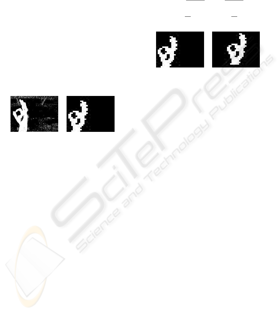
the overall system performance. An example of the
results of this functional block can be seen in Figure 8.
g(x, y) =
(
1 if
h
P
M−1
m=0
P
N−1
n=0
f(x + m, y + n)
i
≥ 60
0 otherwise
(6)
(a) (320x240) (b) (32x24)
Figure 8: Segmented image with noise (a) and Reduced
without noise (b)
2.6 Segmented Region Centring
The function of the Image Centralization block is to
translate the region containing the hand to the centre
of the image. This translation is important in order to
standardize its position, which helps to increase the
neural network efficiency rate. The operation is per-
formed by calculating the difference between the cen-
tre of mass of the hand region and the centre of the
image. The translation is done based on the result of
this computation. The centre of mass is obtained by
means of Equations 7, 8, and 9 (Gonzalez and Woods,
1992). The difference between both centres (hand and
image) is obtained by using Equation 10.
As seen in Equation 9, the centre of mass is calcu-
lated by dividing the sum of the X,Y coordinates by
the area of the region to be translated. The transla-
tion parameters are obtained by subtracting the X,Y
coordinates of the centre of mass from the X,Y co-
ordinates of the image centre (32/2 and 24/2, respec-
tively). The result of a translation operation can be
seen in Figure 9.
Area =
X
x
X
y
f(x, y) (7)
Coord
x
=
X
x
X
y
xf(x, y) Coord
y
=
X
x
X
y
yf(x, y)
(8)
X
c
=
Coord
x
Area
Y
c
=
Coord
y
Area
(9)
Dif
x
=
32
2
− X
c
Dif
c
=
24
2
− Y
c
(10)
(a) (b)
Figure 9: Original image (a) and After translation (b)
3 NEURAL NETWORK FOR
GESTURES RECOGNITION
The gestures interpretation is accomplished through
a RAM-based neural network (n-tuple classifier),
which is implemented in the FPGA. This is a
weightless neural network, operating on binary data
only, and so facilitating its implementation in hard-
ware (Austin, 1998). The gestures that are used to
command the robot’s actions are made by the user,
determining the following commands:
• Halt
• Go
• Go Back
• Left 90
o
• Left 45
o
• Right 90
o
• Right 45
o
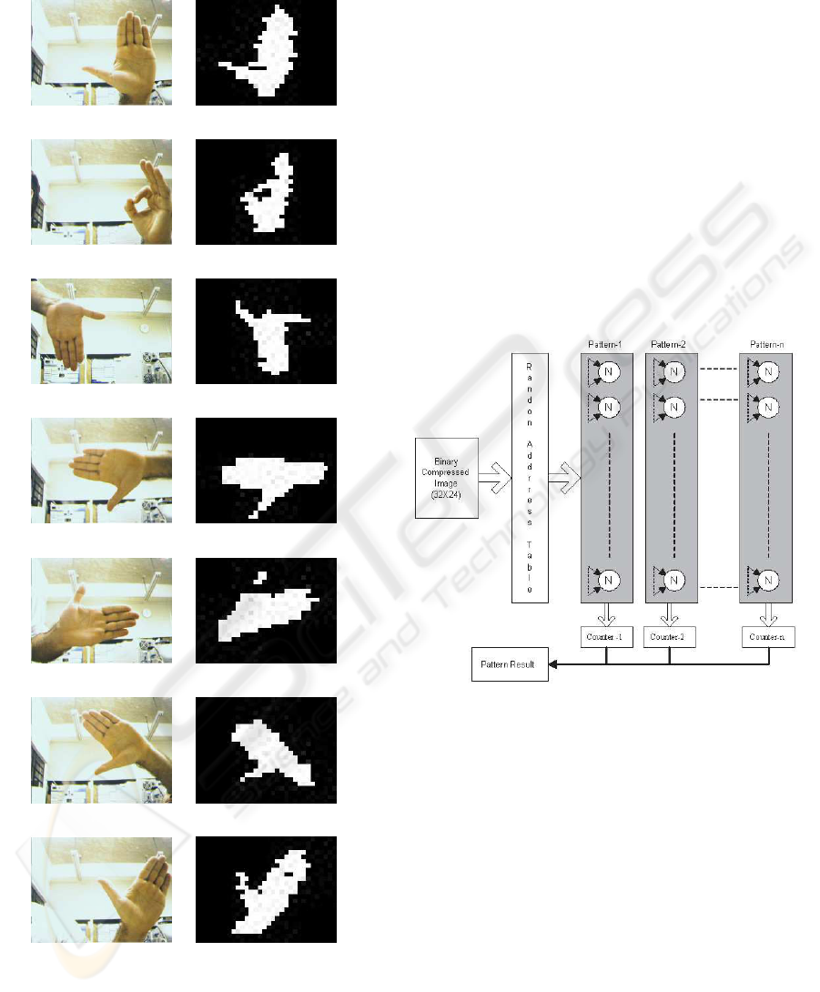
These commands are shown in Figure 10, with im-
ages generated from our FPGA implementation. The
first column exhibits the images obtained from the
camera, and the second one shows the correspond-
ing images supplied to the neural network, after the
pre-processing steps described in Section 2. Gestures
can be changed or added according to user require-
ments, using the system on-chip training capabilities.
Once the system is initialized, it waits for one of the
valid gestures to start executing a navigation com-
mand. When a gesture is recognized, the correspond-
ing action is performed until other valid gesture is de-
tected by the system.
A REAL TIME GESTURE RECOGNITION SYSTEM FOR MOBILE ROBOTS
211
(a) Halt (b) Halt
(c) Go (d) Go
(e) Go Back (f) Go Back
(g) Right 90
o
(h) Right 90
o
(i) Left 90
o
(j) Left 90
o
(k) Right 45
o
(l) Right 45
o
(m) Left 45
o
(n) Left 45
o
Figure 10: Gesture set recognizable by the robot: RGB in-
put images (a),(c),(e),(g),(i),(k),(m) and Corresponding im-
ages sent to the neural network (b),(d),(f),(h),(j),(l),(n)
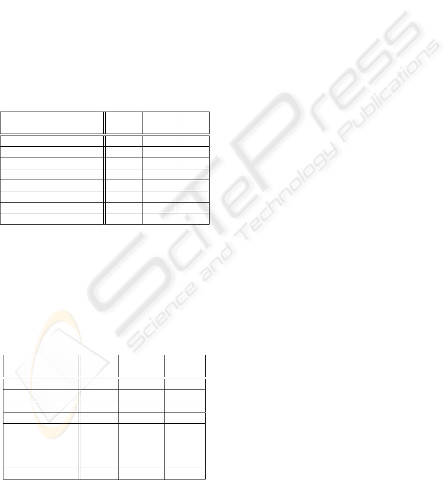
The neural network used by our vision system is
implemented as the structure depicted in Figure 11.
It is composed by memory cells (neurons represented
by N) addressed by the input data. The input data is
in the form of a 768-bit vector (32x24 pixels), which
represents a gesture after the pre-processing stages.
For each pattern there are 96 neurons of 256 bits each
(8-input neurons), each of them addressed by 8 pixels
of the image. Pixels linked to the neurons input are
connected in random fashion by means of the Ran-
dom Address Table. During the training phase, a given
gesture is associated to a group of neurons, and all the
cells selected by the address generated from the pix-
els combination are set to a binary value 1. For each
gesture pattern there is an specific set of neurons. The
recognition is accomplished through the sum of all
neurons output signals counter, which is associated
to the corresponding pattern.
Figure 11: RAM-based neural network
4 EXPERIMENTAL RESULTS
This section presents some experimental results re-
lated to the vision system described in this paper, in
particular resources, performance and efficiency fig-
ures. Before doing so, we present an overview of the
hardware and software resources employed.
The development of the system has been done
using Altera Quartus II V3.0, an EDA (Electronic
Design Automation) tool for FPGA development.
The hardware platform is composed of a Nios-
Stratix development board (Altera, 2004), featuring
an EP1S10F780C6 FPGA. This reconfigurable device
contains 10.570 logical elements, and 920 Kbits of
RAM memory.
ICINCO 2004 - ROBOTICS AND AUTOMATION
212
The data of Table 1 shows the resources required
for the FPGA implementation of the vision system.
This information was obtained from the compilation
reports supplied by the EDA tool. It should be noticed
that the neural network, in spite of being mainly com-
posed of memory cells, uses a significant amount of
logical elements in comparison to other blocks of the
system. This is due to the implementation of an inter-
nal bus capable of supplying all the image input bits in
parallel, a crucial feature for the system performance.
All blocks of the system are able to process at least
30 frames per second, which is the maximum rate
supported by the camera. As only 27.94% of the
FPGA capacity is used, it should be possible to add
new image processing functions to the vision system,
if required by other applications.
Table 1: Resouces usage: RAM Memory (Mem), Logi-
cal Elements (LE), and fraction of Logical Elements used
(LE(%)); Base: EP1S10F780C6 FPGA
Blocks
Mem
(Kbits)
LE
LE
(%)
Camera Control 0 71 0.67
Pixel Read 0 84 0.79
RGB2HSI 0 684 6.47
Segmentation 0 33 0.31
Filter and Compression 5 252 2.38
Image Centralization 1 180 1.70
Neural Network 229 1650 15.61
Total 235 2.954 27.94
On the Table 2 is presented the performance results
archive for each blocks of the system. The RGB2HSI
block is the slowest (31.88 frames per second), be-
cause it needs implementing operation like division
and multiplication and a complex hardware is neces-
sary for compute these equations.
Table 2: Performance of the system blocks: Operation Fre-
quency (OF), Image Size(IS) or Number of Neuron (
Ä
**),
and Frames per Second (FS); Base: EP1S10F780C6 FPGA
Blocks
OF
(MHz)
IS FS
Camera Control 269.11 - -
Pixel Read 422.12 320x240 1374
RGB2HSI 16.88 320x240 31
Segmentation 109.79 320x240 1429
Filter and
Compression 48.89 320x240 212
Image
Centralization 18.50 32x24 3437
Neural Network 73.48 96
Ä
** 382708
The efficiency of the recognition process has been
evaluated in order to determine if the hit rate is satis-
factory. During the process, we have found that the
number of samples used during the training phase of
the neural network plays a significant role in the final
results.
To determine that 50 samples of each gesture are
enough, the values of the neural network counter for
each recognition operation were analyzed. The neural
network model used in this system allows the counter
to vary between 0 to 95, the greatest value determin-
ing the winner pattern of the recognition process. By
analyzing the difference between counters, it was con-
cluded that using less than 50 samples in the training
process results in small differences between the win-
ner pattern and the others. This clearly indicates a
low confidence degree. On the other hand, using more
than 50 samples for training tends to saturate the neu-
ral network, as a large number of counters become
close to the maximum value. This also reduces the
confidence degree.
Once defined the number of samples for training,
the efficiency test was performed. The system was
trained to recognize 7 gestures, all of them repre-
sented by the internal part of hand, as seen in Sec-
tion 3. A total of 700 gestures were presented to the
system (100 of each type), where variation of the dis-
tance and inclination of the hand in front of the cam-
era was made to turn the system more reliable. For
each of them it was verified if the recognition was cor-
rect, wrong, or not possible. After several testing runs
it was concluded that 50 samples of each gesture are
enough to obtain 99.57% of hit rate. One of the main
reasons to achieve this efficiency level is the transla-
tion of a gesture to the centre of the image sent to the
neural network. The results of this analysis can be
seen in Table 3. The True Recognition column shows
the percentage of correct interpretation of the gesture,
while the False Recognition column shows the per-
centage of the gestures wrongly interpreted. Finally,
the column labed No Recognition shows the rate of
unrecognized gestures.
5 CONCLUSION
In this paper we have shown a real time gesture recog-
nition system for mobile robots, implemented as a
SoC using FPGA technology. The main task of the
system uses a RAM-based Neural Network to rec-
ognize seven gestures. The primary motivation for
the development of this vision system is its integra-
tion to a mobile robot intended to help people with
disabilities and requiring alternative communication
interfaces. The resulting system showed to be ro-
bust, allowing the high performance required for real-
time processing (30fps). This performance could
A REAL TIME GESTURE RECOGNITION SYSTEM FOR MOBILE ROBOTS
213
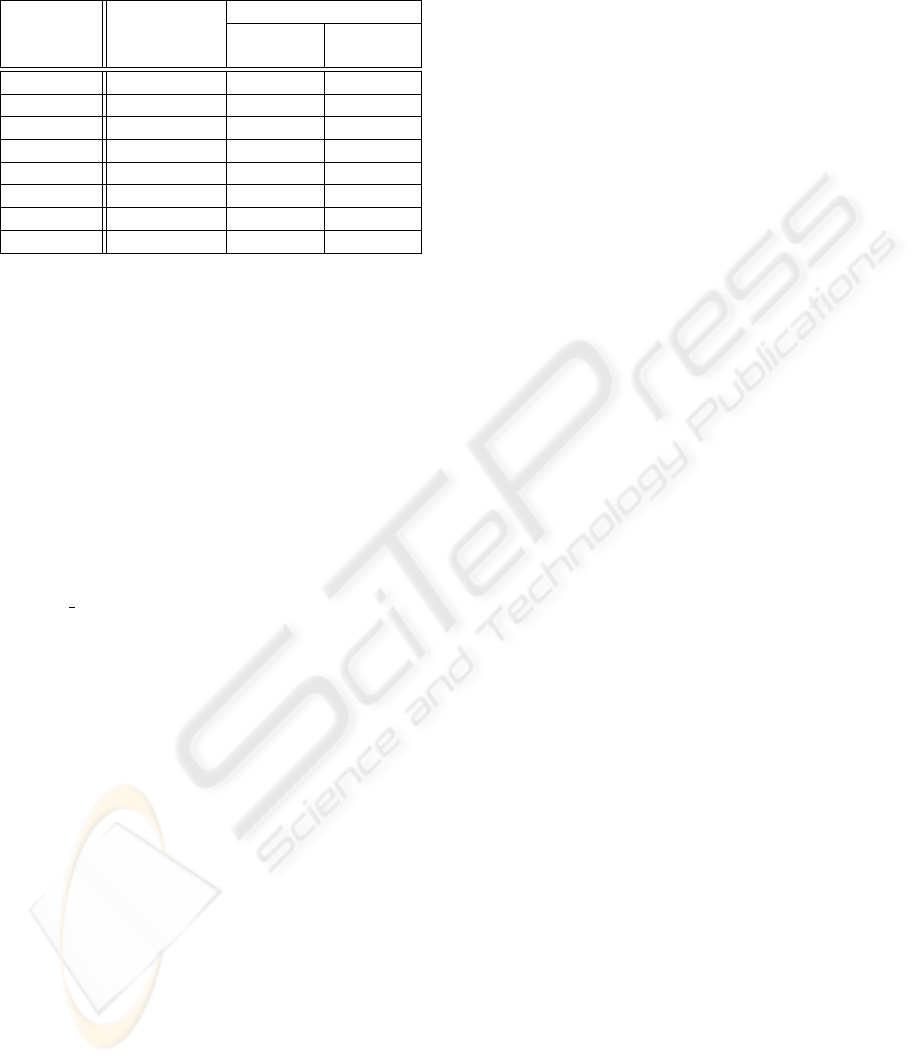
Table 3: Recognition rates for seven gestures: True Recog-
nition (TR), No Recognition (NR), and False Recognition
(FR)
Gestures TR (%)
Error (%)
NR FR
Halt 100 0 0
Go 100 0 0
Go Back 98 0 2
Right 90
o
100 0 0
Left 90
o
100 0 0
Right 45
o
99 0 1
Left 45
o
100 0 0
Total 99.57 0 0.43
only be achieved by means of parallel processing
of functional blocks, which allows operations to be
pipelined. The system efficiency is also high, with a
true recognition rate of 99.57% for the 7 gestures used
in the experimental analysis. These can be changed or
extended by means of the system on-chip training ca-
pabilities.
REFERENCES
Altera (2004). Nios Development Kit, Stratix Edition.
http://www.altera.com/products/devkits/altera/kit-
nios
1S10.html.
Austin, J. (1998). RAM-Based Neural Network. World Sci-
entific Publishing Co. Pte. Ltd., London.
Cardoso, J. M. P. and Neto, H. C. (2003). Compilation for
fpga-based reconfigurable hardware. IEEE Design &
Test of Computers Magazine, 20(2):65–75.
ChiZhang, P. W. (2000). A new method of color image seg-
mentation based on intensity and hue clustering. In
IEEE International Conference on Pattern Recogni-
tion - ICPR, volume 3, page 3617.
Costa, L. d. F. and Cesar Jr., R. M. (2000). Shape Analysis
and Classification. Phillip A. Laplante, New York.
Cummings, R. E., Pouliquen, P., and M. Lewis, A. (2003).
A vision chip for color segmentation and pattern
matching. EURASIP JASP, pages 703–712.
Electronics, Q. (2004). http://www.quasarelectronics.com-
/c3188a.htm.
Gonc¸alves, R., Wolf, D. F., Rodrigues, M. I., Osorio, L. F.,
Moraes, P. A., Genu
´
ario, L. B., Teixeira, M. A.,
Ribeiro, A. A. L., Romero, R. A. F., and Marques,
E. (2001). Architect-r: A system for reconfigurable
robots design - an overview and initial results. In
VLSI-SOC’01, volume I, pages 60–64.
Gonc¸alves, R. A., Moraes, P. A., Cardoso, J. M. P., Wolf,
D. F., F. M. M., Romero, R. A. F., and Marques,
E. (2003). Architect-r: a system for reconfigurable
robots design. In Proceedings of the 2003 ACM sym-
posium on Applied computing. ACM Press New York,
NY, USA.
Gonzalez, R. C. and Woods, R. E. (1992). Digital Image
Processing. Addison-Wesley Company, New York.
Oldfield, J. V. (1995). Field-programmable gate arrays:
reconfigurable logic for rapid prototyping and imple-
mentation of digital systems. John Wiley & Sons, Inc.
Philips (2003). The i2c-bus specification.
http://www.semiconductors.philips.com/acrobat/litera-
ture9398/39340011.pdf.
Rowe, A. (2002). A low cost embedded color vision system.
IEEE Intelligent Robots and Systems - IROS.
Russ, J. C. (1995). The Image Processing Handbook. CRC
Press, Boca Raton, 2
a
edition.
Swenson, R. L. (2002). A real-time high performance uni-
versal colour transformation hardware system. PhD
thesis, University of Kent at Canterbury, Canterbury -
Kent.
Thrun, S., Schulte, J., and Rosenberg, C. (2000). Interaction
with mobile robots in public places. IEEE Intelligent
Systems, pages 7–11.
Turk, M. (2004). Computer vision in the interface. vol-
ume 47, pages 60–64. ACM Press New York, NY,
USA.
Waldherr, S., Romero, R., and Thrun, S. (2000). A ges-
ture based interface for human-robot interaction. Au-
tonomous Robots, 9(7):151–173.
Zemcik, P. (2002). Hardware acceleration of graphics and
imaging algorithms using fpgas. In Proceedings of the
18th spring conference on Computer graphics, pages
25–32. ACM Press New York, NY, USA.
ICINCO 2004 - ROBOTICS AND AUTOMATION
214
