SUPERVISION AND TELECONTROL OF A RADIO
BROADCASTING SYSTEM VIA INTERNET
Joan Aranda
Automatic Control and Computer Engineering Department
Universitat Politècnica de Catalunya (UPC)
Pau Gargallo,5. 08028 Barcelona
Eduard Sanz
Head of Telecontrol Systems Department
Difusió Digital S.T.S.A-Tradia
Key words: Telecontrol, Remote Supervision, Internet, SCADA, Radio broadcasting.
Abstract: In this paper a recent application is showed that uses Internet as a supervision tool and remote control of
a network of radio-TV relay stations to offer a better service to future clients. The relay stations network
occupies a region of about 30.000 km
2
. The operator of this telecommunications network counts with a
SCADA system which permits to the operator monitoring and control of the whole network. With the
presented application users of the network can access to real time information about relevant aspects of
the emission or change some parameters at anytime and from anywhere thanks to internet. The aspects of
access security and safe communications have been taken care specially.
1 INTRODUCTION
Telecontrol and remote supervision of industrial
applications have been growing up everywhere.
They are especially important on distributed systems
when they extend on a vast territory.
In this paper we show a particular
implementation on a radio broadcasting system, and
its relay stations network. The network extends for a
region of about 30.000 km
2
most of them occupied
by mountains with difficult road access to the relay
stations on winter.
The operator of this telecommunications network
(the operator, from now on) needs a telecontrol and
supervision system of its radio broadcasting system,
including infrastructures and equipment, to be
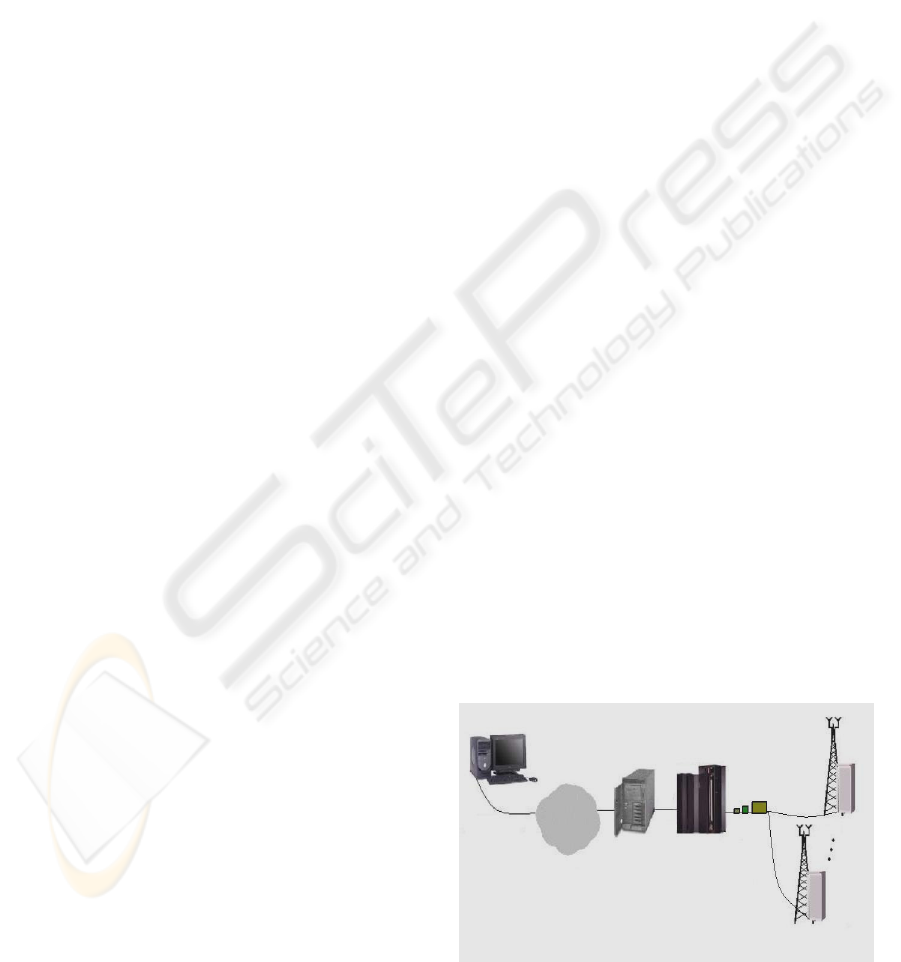
offered as a new service to its clients. The central
application of this system counts on a SCADA in
real time with a continuous polling against a
communications front-end. This SCADA
concentrates the communications with different
remote relay stations (fig 1).
The operator considered the viability to carry out
the implementation of a software application that
allows resolving the limitations of security of its
SCADA system and that makes possible the access
of a third party to supervising and remote control of
infrastructures property of the operator.
The addition of new functionalities that will be
attractive for this type of users, as radio stations or
TV channels, tries to be an added value for the
future clients. They will appreciate these
functionalities at the time of making the decision to
contract certain services of housing with the
operator.
Figure 1: General system architecture
INTERNET
Clien
t
WEB
Se
r
ve
r
SCADA
Front-End
375
Aranda J. and Sanz E. (2004).
SUPERVISION AND TELECONTROL OF A RADIO BROADCASTING SYSTEM VIA INTERNET.
In Proceedings of the First International Conference on Informatics in Control, Automation and Robotics, pages 375-378
DOI: 10.5220/0001143303750378
Copyright
c
SciTePress

2 OBJECTIVES
Our basic objective consists of analyzing the users’
requirements and designing an open telecontrol
system, using the existing infrastructure of remote
stations of telecontrol and the SCADA system,
property of the operator.
Initially, this service will be offered to the
operator clients, through a reduced bandwidth
communication channel (commuted telephone
network, for example).
We considered that the necessary functionalities
to make the product attractive to the client are the
following ones:
1. Monitoring of Telecontrol customized data at
client level (1 client - N signals).
2. The visualization of digital states of channels
connected to the system in "real time"
(depending solely of the bandwidth available).
3. The visualization of analogical measures in "real
time".
4. Visualization of a listing with the last events
generated by the channels that belong to a certain
client.
5. Possibility of including connections to other
static pages, or send a mail to the contact person
(webmaster).
6. Safe connection. The connection with the client
must be established through a safe connection,
with some type of certificate and encoding in the
case of control commands.
7. Execution of commands. Some actions will be
allowed to the client on certain channels, with
the necessary warning interface and user
agreement of the type of action that will be
executed. A log file of the commands sent by all
the users will be generated.
8. Movement between synoptic screens. The
administrator will be allowed to connect several
pages of clients, giving the possibility of moving
from one page to another just clicking over some
icon within the visualization area. A registration
of visits will be generated.
9. Storage of analogical measures. Analogical
values will be registered in time intervals defined
by the client and up to a maximum number of
values defined by the administrator. The
necessary interface for the selection of these
parameters will be designed.
10. Conversion functions and thresholds of
analogical measures. A simple conversion
function (proportional and offset) will be
implemented for the presentation of the
analogical values. In addition, maximum and
minimum values for a specific measurement will
be provided, so that, once surpassed those
thresholds, the corresponding alarm will be
triggered.
11. Evolution Graph of analogical measures. A
graph with the values of the obtained analogical
measures of the periodic interrogation of point 9
will be created dynamically.
12. Filtering of events. The user will be allowed to
filter the events by the obtained values.
13. Reports screen. A page for internal use will be
created to enable fast generation of reports with
the filtering of events described previously.
14. Automatic warning by email of certain events. A
necessary time of delay in the transitions from 1
to 0 and vice versa will be defined in order to
don’t disturb the client. A sent messages Log
File will be generated.
15. Automatic warning by SMS to GSM mobile
telephones. The telephone number will be chosen
by the user and a maximum number of messages
will be sent. Log with the sent messages will be
generated.
16. Slow video show. A page will be implemented
where slow video will be visualized (images
JPEG, GIF...). The sample time will be selected
by the user in relation with the bandwidth
available.
The most important processes must leave files of
log, giving the possibility of tracking possible
malfunctions. Also the operator wants to give this
service of supervision and remote integral control to
an undetermined number of clients. Under this
premise, the system must be easily scaleable.
3 SYSTEM DESIGN AND
SPECIFICATIONS
The proposed system shows incalculable value for
the clients of the operator, so it guarantees a
continuous test service anytime at anywhere. Thus,
the works of maintenance and tracking of failures or
incidences will be much more effective with a
system of the raised characteristics. The
determination of the origin of a problem will be
considerably faster and it will returns in a superior
quality service.
In order to understand usual problems we will
show up some examples. A typical client of the
operator could be a FM radio station. A technician in
charge of emitters and relay stations of this radio
station could need to know the nominal power exit
and other important parameters of the relay station
under which he/she is making field measures.
Another example: most of relay stations do not have
permanent personnel the twenty-four hours/day that
ICINCO 2004 - ROBOTICS AND AUTOMATION
376
can monitor (from the studies) the continuity of the
transmission. Thus, the possibility of connection
with a personal PC from the particular address of the
guard person would allow avoiding unnecessary
displacements.
For that reason the final solution is not bound to
a specific platform or communication channel. The
application will allow the remote connection using
the telephone lines, or even the connection by means
of a data line of a GSM movable telephone.
Given the uncertainty in the final number of
concurrent users, the use of an existing network like
Internet is valued very positively, in front of the
implementation of a specific remote access system
for the clients of this service.
3.1 The corporative control system
The hardware architecture of the control center is
formed by two servers HP9000, a disc Array and
two terminal servers of 16 ports each one, which
connect with the front-end of communications, as
well as two graphical consoles with 21"monitors.
The servers form a cluster MC/Service Guard,
connected by network and with the sufficient
redundancy so that an error in one of the
components does not interrupt in a significant form
the service. It counts on redundancy of LAN
interfaces, mirror discs and duplicity of ventilation
and power supplies, and also redundancy of CPUs in
the main server. The terminal servers connect with
the front-end of communications through a passive
commutation which is controlled by one of the high
availability processes of the MC/Service Guard
system.
The data management is made with an Oracle
relational database, for the historic and configuration
data, a real time data base that stores the values and
states of the system, an alarms data base that
manages the different events based on its critical
issue, and the operator answers to these events.
The system allows the supervision and
telecontrol of up to 254 remote stations on a same
communications line by using Gestel protocol. The
connection of these becomes through the corporative
network of cross-connect nodes, using V-24
interfaces and point-multipoint structures. At the
moment there are 10 remote lines operatives and
could be up to 16 with the existing hardware.
In its present configuration, the system reports
states, alarms and is able to execute commands in a
total of 92 remote locations, on a total of 780
equipments. The control carried out on these
equipments implies the configuration of 7400 digital
inputs, 1700 digital outputs and 500 analogical
measures. This information is captured by the
remote stations through input/output cards or via
RS-232.
The system also allows the communication with
other servers through UDP and TCP/IP, using the
standard SNMP (Simple Network Management
Protocol).
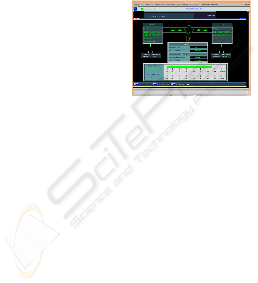
Figure 2: SCADA Interface: Synoptic screen for real time
operation on a television relay station.
3.2 Implementation
The proposed solution consists of the following
elements (figure 3):
1. Data base SQL Server 7.0: with information
about the clients, channels, parameters, etc. The
historical data are stored in the Oracle data base
of the server where the SCADA runs.
2. Data base ORACLE: Holds the historical
information of alarms and the configuration
parameters of the digital output signals.
3. The web server: Acts as application interface.
The client uses it to extract information from the
remote relay stations and to set up the required
services on its channels. The system
administrator has the corresponding Webpage
interface.
4. ActiveX Components: They supply essential
utilities for the assembly of the application.
5. NT Services: the system has three own services
in execution: tracking of digital channels,
tracking of analog channels and the registration
of the captured information.
The communication settles down through the
following sequence of operations (fig.4):
1. The Web server receives requests from the
clients, unloading static and dynamic images that
are kept in the client PC.
SUPERVISION AND TELECONTROL OF A RADIO BROADCASTING SYSTEM VIA INTERNET
377
2. The client makes the request of the telecontrol
information of the contracted services.
3. The server requests the information in real time
through protocol SNMP to the corporative
telecontrol system.
4. The server offers the information to the client
and it refreshes the representation in the local
machine. The operation takes place at the
frequency fixed by the system administrator.
5. In addition to the real time information, the client
can ask for historical information that the Web
server acquires from the corporative control
system data base.
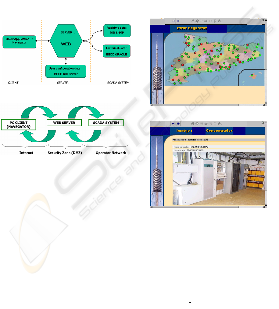
Figure 3: Application data structure
Figure 4: System operation.
4 RESULTS
A friendly and functional interface has been
designed that allows the clients continuous
monitoring and remote control over the relay
stations network (figure 5).
It solves functional limitations of the SCADA
system as the massive management of alarms. This
kind of services and the automatic generation of
reports for the internal use of the own operator have
made of the developed application a profitable
investment, only for the own management of the
network quality.
In addition they have been introduced new
broadcasting service functionalities that will call the
attention of the potential clients. This will derive in
the benefit of new services to contract, as they can
be the transmission of slow video, the inclusion of
images to its own Web, monitoring cameras, transit
(through Digital Audio Broadcasting, for example),
beauty cams to show the weather conditions in
different places, etc. (figure 6).
A complete interface has been created to allow
the client changing some parameters without
depending on the availability of the system
administrator to carry out some service
modifications. For instance, the time between
captures of analogical values (sample rate) or the
email address where the user will receive the
notification of the events that he/she previously has
programmed.
Figure 5: Relay stations network of the operator
Figure 6: Real time video from a concentrator
REFERENCES
Orfali R., Harkey D. (1998) “Client/Server Programming
with Java and CORBA” Second Edition. John Wiley
& Sons, Inc., New York.
Stallings, William, (1994) “SNMP, SNMPv2, and CMIP:
The practical Guide to Network-Management
Standards”, Addison-Wesley Publishing Company.
www.verising.com; Implementing Web Site Client
Authentification Using Digital Ids.
www.Microsoft.com:
ASP Technology Overview.
Implementing a Secure Site
with ASP
ICINCO 2004 - ROBOTICS AND AUTOMATION
378
