
A SKELETON BASED METHOD FOR EFFICIENT 3D OBJECT
LOCALIZATION
Application to teleoperation
Djamel Merad, Narjes Khezami, Malik Mallem & Samir Otmane
Complex System Lab.
University of Evry Val d’Essonne
Evry, France
Keywords: 3D free form object localization, Teleoperation, 2D & 3D skeletonization.
Abstract: Our aim is to develop a vision system for teleoperation to localize an object. This system has to be used
through Internet connection. The recognition problem addressed in this paper is to localize a 3D free-form
object from a single 2D view of 3D scene. Using a skeletonization process allows to obtain two graphs, the
first one representing an object in the scene (2D skeleton) and the second one representing a database object
(3D homotopic skeleton). The method encodes geometric and topological information in the form of a
skeletal graph and uses graph isomorphism techniques to match the skeletons and find the one-toone
correspondences of nodes in order to estimate the object’s pose. Knowing skeleton is a set of lines centred
within the 3D/2D objects, our method transforms the problem of free form object localization into points
and lines pose estimation. Some experimental results on real images demonstrate the robustness of the
proposed method with regard to occlusion, cluster and shadows.
1 INTRODUCTION
A system of teleoperation allows an operator to
achieve a task from afar, while moving him away
from his environment of work and machines that he
controls. Thus, the teleoperation eliminates risks
raising dangerous works as the spatial exploitation
or the poisonous substance manipulation. To help
the operator to achieve his work in a more efficient
way, it is possible to give him the aid offered by
other users or by robot with a certain degree of
autonomy. Assistance robots completes the human
faculties and allows the system to take advantage of
machine capacities to achieve the repetitive works or
difficult one at the physical level, and of the expert's
ability human to watch, to feel and to react at the
precise moment. Among applications of human-
machine cooperation are the telesurgery and the
cooperative manipulation. In the telesurgery, the
goal is to combine the high technologies with the
surgical experience to get less traumatize and which
demand less resources (
Ottensmeyer, 1996). In the
cooperative manipulation, an efficient coordination
between the man and the machine to manipulate
objects are looked for. For example, Arai and al
(
Arai , 2000) developed a system in which a robot
helps a human operator to transport one long object.
Thanks to the combination of the perception and of
the interpretation of the environment on behalf of
two entities, it is possible to accomplish an
impossible task to achieve by an alone entity.
The subject of this work is to develop a vision
system devoted to the augmented reality context. A
teleoperation system has been developed, where it is
possible, for everybody, to connect by internet. It is
the Augmented Reality Interface for Teleoperation
on the Internet system “A.R.I.T.I” (
Otmane, 2001).
But, in this system, it is now not possible to localize
a moved object and to match a model on it. Before
obtaining a whole system, some steps are necessary.
First the system has to be initialized: the interesting
object must be localized. The second step is the
matching step. In the area where it is possible to find
the object, we extract some features in order to
match the object and its model. Then an error
computation allows obtaining a good accuracy to the
model position. In the third step, we use the previous
knowledge in order to predict the new position of the
object. It is the prediction step.
Many researches leaded in the localization
domain, but they don’t study the free form object
95
Merad D., Khezami N., Mallem M. and Otmane S. (2004).
A SKELETON BASED METHOD FOR EFFICIENT 3D OBJECT LOCALIZATION - Application to teleoperation.
In Proceedings of the First International Conference on Informatics in Control, Automation and Robotics, pages 95-101
DOI: 10.5220/0001145100950101
Copyright
c
SciTePress
localization and they rarely discuss the occlusion
problem. Last years we find in literature some works
try to resolve the free form object localization using
the silhouettes (Chen, 1998), object appearances
(Camps, 1998) and shape from shading
(Worthington, 2001).
These researches leaded in the identification
domain, but they rarely study the free-form object
localization and the occlusion problem. We notice
that tests are realized with synthetic images or they
are not done in the real conditions. To solve these
lacks, we have used the skeleton method as is
explain below.
Conversion of 2D and 3D objects into a skeletal
representation forms an essential step in many image
processing and pattern recognition applications. For
example, in document analysis, drawing recognition
and offline script recognition. Most of the
topological structure of objects, and the information
contained in the outline of their shape, are preserved
in the skeleton.
In recent work, Siddiqi and al have resolved the
problem of 2D shape matching using shock graph
representation corresponding to a 2D skeletal
(Siddiqi, 1999a) this compact representation has
been used for indexing. In (Macrini, 2002a)
(Macrini, 2002b) Macrini and al unify shock graph
indexing, aspect graph and matching techniques to
yield an effective method for view-based 3D object
recognition.
Our aim is to develop an on-line system which
will be able to localize a moved free form object.
This system will be an improvement to the ARITI
system and will be reached by internet. So, in order
to give a good reactivity to the users, all the
processes we develop have to be “real time”. Our
approach is summarized as follows. Each 3D model
is stored with their 3D skeletal graph. We compute
the 2D skeleton from the image and we generate
their 2D skeletal graph as described in section 3.
These characteristics are used to compare the image
with other 3D skeletal graph in database using the
graph matching algorithm presented in section 4.
The resulting match gives the pose of the object as
well as its identity, the methods used to determine
the object pose is presented in section 5. Section 6
shows the experimental protocol used to validate the
method. Finally, conclusion and future works are set
out.
First part of this paper presents short description
of the ARITI system.
2 ARITI INTERFACE
The ARITI system (Otmane, 2001), is a web site
allowing any user with a Java compatible web
browser to control our 4 degree of freedom robot.
This site is opened for public on 1999 at the
http://lsc.cemif.univ-evry.fr:8080/Projets/ARITI/
and it is added in NASA Space Telerobotics
Program web site on February 2000.
The ARITI system has been implemented on a
PC Pentium 233 MHz with a 128 Mo RAM, under
Linux operating system. The PC is equipped with a
Matrox Meteor video acquisition card connected to a
black and white camera. Thus, images of the
environment, within which the robot is, can be
obtained and enhanced with virtual models. On the
other hand this PC is connected to four degrees of
freedom robot via a common RS232 serial link. The
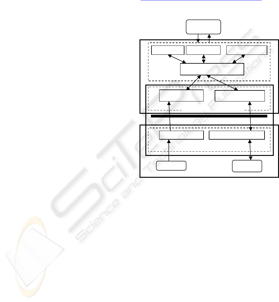
figure 1 shows how a communication between an
operator (client) and remote robot system is done.
Two servers are implied in this communication.
Video server performs image compression and
transfer to the client. And robot server allows to
telecontrol the robot. The ARITI interface is written
based on Java object programming language. Hence,
allowing the execution of the Applet using any
recent Internet Browser.
Teleoperation Telesupervision Teleprogrammation
IHM Module
Mixed Reality (RV& RA)
Operator
Camera
Robot
Commands Client
Communication Module
Images Client
Communication Module
Images Server
Internet
/ Intranet
Commands Server
Figure 1: ARITI architecture
ICINCO 2004 - ROBOTICS AND AUTOMATION
96
3 NEW FREE FORM
LOCALIZATION
In this section we describe a novel method for
searching and locating 3D free-form objects. The
method encodes the geometric and topological
information in the form of a skeletal graph. Uses
graph matching techniques to match the skeletons
and to compare them in order to find the one-to-one
correspondences of nodes so that the pose of the
object is estimate.
The matching procedure is expensive and must
be used sparingly. For large databases of object
models, it is simply unacceptable to perform a linear
search of the database. Therefore, an indexing
mechanism is essential for selecting a small set of
candidate models using the eigenvalue
characterization presented in section 4. Once a
candidate is retrieved by indexing mechanism, we
exploit this same eigen characterization of
hierarchical structure to compute a node-to-node
correspondence between 2D skeletal (scene) and 3D
skeletal graph (model).
Knowing that the skeleton is a set of lines
centred within the objects (3D and 2D), our method
transforms the problem of freeform object
localization into points and lines pose estimation.
The localization of a correct model implicitly
indicates the recognition of the model.
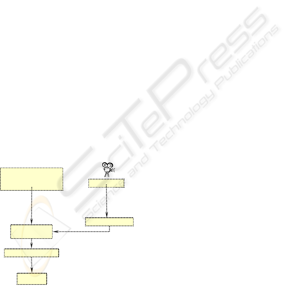
The object recognition system we proposed here,
as illustrated in figure 2, comprises three primary
techniques: 2D and 3D skeletonization process,
graph isomorphism and robust pose estimation.
3.1 2D Skeletonization
The skeleton of a two-dimensional object is a
transformation of the shape object into a one-
dimensional line. Skeleton representation as
introduced by Blum (Blum, 1967). Since, many
skeletonization algorithms have been reported in the
literature (Smith, 1987) (Lee, 1993). Existing
skeletonization approaches can be classified into two
categories: discrete methods (thinning methods,
grassfire methods, distance map (Rosenfeld, 1966),
(Nilsson, 1997) ) and potential field methods (Kégl,
2002), (Siddiqi, 1999b), (Tek, 1998)) and
continuous methods (using Voronoi diagram (Attali,
1997), (Fabbri, 1999)). On summary, discrete
methods can localize skeletal points accurately, but
often at the cost of altering the object’s topology and
are noisy sensitivity. Continuous methods (using
Voronoi diagram), preserve topology, but heuristic
post-processing are introduced to remove unwanted
edges to preserve the homotopy, but then they are
less sensitive to the noise.
A hybrid skeletonising method based on the
combination of two techniques (Voronoi and
distance map) is used in this application (Merad,
2004). This method regroups the advantages of each
one, such as homotopy preservation, good
localization, and robustness to the noise.
3.2 3D skeletonization
There are two types of skeletons on 3D images:
medial surfaces and medial curve. A medial surface
is a set of object voxels forming a surface of unit
thickness, and a medial curve is a set of object
voxels forming a curve of unit width also called
homotopic skeleton. The 3D skeleton used in this
context is the homotopic skeleton.
To thin the volume, the distance field of each
voxel in the object is computed. The distance
transform (Rosenfeld, 1966) at an object voxel is the
minimum distance from the voxel to the boundary of
the volumetric object. Various metrics can be used
to compute the distance transform, such as a quasi-
Euclidean (Borgefors, 1996) or a true Euclidean
metric (Saito, 1994). The distance field or distance
transform value (DT) of a voxel is the radius of a
sphere centered at that voxel. Such a sphere will be
tangential to the boundary of the 3D object. If we fill
in the sphere, we can reconstruct a part of the object
touching the boundary.
To compute the homotopic skeleton, we used the
algorithm presented in (Gagvani, 1999). The authors
described a thinning technique using a thinness
parameter.
3D Model
+
homotopic skeleton
(
3D
)
2D Ima
g
e
Node’s
matchin
g
2D/3D
2D Skeletonization
Pose determination
Projection
R, T
2D Primitives
3D Primitives
Figure 2: 2D/3D free form localization
A SKELETON BASED METHOD FOR EFFICIENT 3D OBJECT LOCALIZATION - Application to teleoperation
97
3.3 Generation of the Skeletal Graph
After thinning and clustering, the skeletal points are
unconnected. To utilize the shape graph matching
(Shokoufandeh, 2001), the points have to be
converted to a directed acyclic graph (DAG). We
also have to ensure that the shape information is
preserved during this process and that the method is
tolerant enough so that minor changes in the position
of skeletal points do not produce drastically different
shape graphs. We first generate an undirected
acyclic shape graph out of the skeletal points, by
applying the Minimum Spanning Tree (MST)
algorithm, with all the edges weighted proportional
to their distance transform see (Merad, 2004)
(Gagvani, 1999). A directed graph is created by
directing edges from the voxel (or pixel for the 2D
skeleton) with the higher distance transform to the
one with lower distance transform.
In principle, it is similar to the shock graph
concept in (Shokoufandeh, 2001), where larger
features are directed towards smaller ones. The MST
is sensitive to distance variation at the joints which
could result in incorrect connectivity structure. The
tolerance of the matching process accommodates
these perturbations. Each node in the skeletal graph
represents a segment in the original skeleton. This
node carries information about the local shape of the
segment in the form of a cloud of points, obtained
from the skeletonization process, and associated
with that segment. Each edge in the skeletal graph
corresponds to a joint in the original skeleton. Each
node in the graph also contains the Topological
Signature Vector, which is used for indexing and
also contains the coordinates of each skeletal
segments which is used for pose estimation.
4 MATCHING THE SHAPE
GRAPHS
Given two graphs, one representing an object in the
scene (2D skeleton) (H) and one representing a
database object (3D homotopic skeleton) (G), we
seek a method for computing their similarity and
find the one-to-one correspondences of nodes.
Unfortunately, due to occlusion and clutter, the
skeleton representing the scene object may, in fact,
be embedded in a larger homotopic skeleton
representing the skeleton of the 3D model. Thus we
have a largest subgraph isomorphism problem,
stated as follows: Given two graphs
) , E (VG
11
=
and ), E (VH
22
=
, find the
maximum integer k, such that there exist two subsets
of cardinality k,
1
'
1
EE ⊆ and
2
'
2
EE ⊆ , and the
induced subgraphs (not necessarily connected)
),(
'
11
'
EVG = and ),(
'
22
'
EVH = are isomorphic
(Garey, 1979).
In (Shokoufandeh, 2001), (Shokoufandeh, 1999),
(Siddiqi, 1999a) a matching algorithm is given
which matches 2D shock graphs. At each node in the
graph, a structural “signature” is defined, which
characterizes the node’s underlying subgraph
structure. This signature is a low-dimensional vector
whose components are based on the eigenvalues of
the subgraph’s (0,1) adjacency matrix. The
eigenvalues of a graph (spectral graph theory) carry
important structural information about the graph and
possess important stability properties. Specifically,
small perturbations in graph structure due to noise or
minor shape perturbation will have correspondingly
small effect on the eigenvalues. Matching two
graphs is typically formulated as a largest
isomorphic subgraph problem, whose complexity is
prohibitive.
2
5
1
9
4
10
14 15 16
3
8
11 12 13
17
18 19 20 21 22
6
7
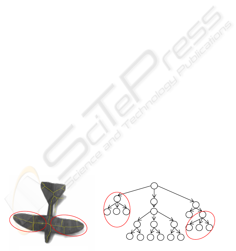
Figure 4: 2D skeleton graph H
Fi
g
ure 3: Plane and 2D skeleton
ICINCO 2004 - ROBOTICS AND AUTOMATION
98
Since contextual graph structure is effectively
encoded in a node’s signature vector, we could
throw away all the edges in the graph and
reformulate the problem as finding the maximum
cardinality, minimum weight matching in a bipartite
graph. In such a formulation, there is an edge
between each node in one graph and each node in
the other, whose edge weight represents the distance
between the two nodes’ structural signature vectors.
Details are presented in (Shokoufandeh, 1999).
5 POSE ESTIMATION
The problem of finding an object‘s pose consists of
determining the position and orientation of a 3D-
object with respect to a camera or a predefined
frame of reference.
To resolve this problem we used the orthogonal
iteration algorithm proposed by Lu in (Lu, 2000).
The authors show that the pose estimation problem
can be formulated as that of minimizing an error
metric based on collinearity in object (as opposed to
image) space. Using object space collinearity error,
they derive an iterative algorithm which directly
computes orthogonal rotation matrices and which is
globally convergent.
6 RESULTS
Before applying our method on the teleoperation
system, we were tested it on a testbench in order to
validate it. For this we were used a Sony camera
with a focal distance of 8 mm, a testbench, a plane
object (toy) of dimensions 22,6×28,4×3,2 cm
3
and a
graphic card of 768×576 pixel
2
. The object plane is
placed to 1,2 m of the camera. We did several
rotations and translations in real conditions, while
taking into account problems of noise, occlusion and
shadows.
Figure 3 shows the image of the plane. Applying
the 2D skeletonization method; we get the skeleton
in yellow. Then, we transform the skeleton in graph
H (figure 4) as is explained in the section 3, where
each node represents a 2D segment.
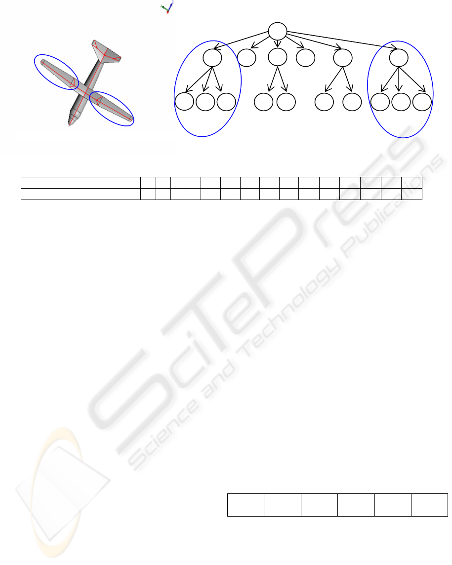
Figure 5 represents the 3D model of the plane
from our database. The corresponding graph G
obtained from the homo-topic skeleton is
represented in figure 6, it is determined by the same
processing that the 2D skeleton graph. Every node of
this graph represents a 3D segment.
Applying the algorithm of graph matching to
find the one-to-one correspondences between the
graph H and the graph G, presented in 4, we obtain
results presented in table 1.
Knowing that each node store geometric
information of 2D and 3D segments, we used the
pose estimation algorithm presented in section 5, we
find the following results:
Table 2: Translation results according Y axis
Trans 20 mm 40 mm 60 mm 80 mm 140 mm
Error 1.3 mm 1.8 mm 1.7 mm 1.8 mm 1.7 mm
Additional results taking into account cluster and
occlusion presence are presented below (figure 7 and
figure 8).
The pose estimation algorithm presented in
section 5 need at least 4 points, at matching stage
our method find 7 most reliable features, which is
sufficient to make a good localization , results are
presented on table 3 and table 4.
2D node (H)
1 2 5 6 7 10 14 15 16 11 17 18 13 21 22
3D corresponding node (G) 1 2 8 9 10 7 15 16 17 4 11 12 6 13 14
Figure 5: Plane and 3D homotopic skeleton
4
3 7
11 12 15 17 16
6
13 14
2
8
9 10
5
1
Figure 6: 3D skeleton graph G
Table 1: Matching Results
A SKELETON BASED METHOD FOR EFFICIENT 3D OBJECT LOCALIZATION - Application to teleoperation
99
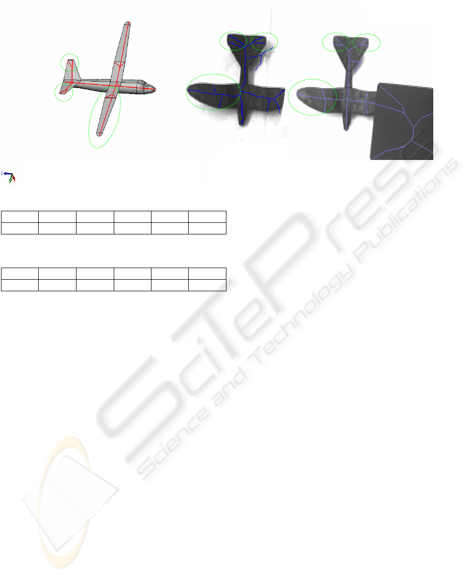
Table 3: Translation results (occlusion)
Trans 20 mm 40 mm 60 mm 80 mm 100 mm
Error 1.6 mm 1.8 mm 2.1 mm 1.8 mm 1.7 mm
Table 4: Translation results (cluster)
Trans 20 mm 40 mm 60 mm 80 mm 100 mm
Error 1.4 mm 2.1 mm 2.1 mm 1.8 mm 1.8 mm
7 CONCLUSION
We have presented our initial effort for localization
3D free form object applying to robot-teleoperation.
Based upon the skeleton, this method transforms the
problem of free form object localization upon points
and lines pose estimation. Due to the strength of the
graph matching, our approach was successfully
applied to different types of noises (shadows
occlusion, clutter …).
However additional attributes can be introduced
to provide a more accurate matching. However, to
improve the localization we must develop more
exact skeletonization algorithm. In a future work, we
develop a fast and robust matching algorithm.
REFERENCES
Arai H., Takubo T., Hayashibara Y., Tanie K., 2000.
Human-Robot Cooperative Manipulation Using a
Virtual Nonholonomic Constraint. In Proceedings
2000 IEEE International Conference on Robotics and
Automation. 2000.
Attali D., Montanvert A., 1997. Computing & Simplifying
2D& 3D Continuous Skeletons. Computing Vision and
Image Understanding, 67(3), pages 261-273,
September 1997.
Blum H., 1967. A transformation for extracting new
descriptors of shape, in Models for the Perception of
Speech and Visual Form (W. Wathen-Dunn, ed.).
Cambridge MA: MIT Press, 1967.
Borgefors G., 1996. On Digital Distance Transforms in
Three Dimensions. Computer Vision and Image
Understanding,64(3):368–376, November 1996.
Camps O. I., Huang C. Y., Kanungo T. 1998. Hierarchical
organization of appearance-based parts and relations
for object recognition. In IEEE Conference on
Computer Vision and Pattern Recognition, pages:685-
691, 1998.
Chen J. L., Stockman G. C., 1998. 3D Free-form objet
recognition using indexing by contour features. In
Computer Vision and Image Understanding,
71(3):334-353, 1998.
Fabbri R., Estozi L.F, Costa L. F., 2002. On Voronoi
Diagrams and Medial Axes. Journal of Mathematical
Imaging and Vision, 17(1), pages 27-40, July 2002.
Gagvani N., Silver D., 1999. Parameter Controlled
Volume Thinning. Graphical Models and Image
Procesing, 61(3):149–164, May 1999.
Garey M., Johnson D., 1979. Computer and Intractability:
A Guide to the Theory of NP-Completeness. Freeman,
San Francisco, 1979.
Kégl B., Krzyzak A., 2002. Piecewise linear
skeletonization using principal curves. IEEE
Transactions on Pattern Analysis and machine
Intelligence. 24(1):59-74, 2002.
Lee S. W., Lam L., Suen C., 1993. A systematic
evaluation of skeletonization algorithms. In
International Journal of Pattern Recognition and
Artificial Intelligence, vol. 7, no.5,pp. 1203-1255,
1993.
Figure 7: Plane and 3D homotopic
skeleton
Figure 8: Plane and 2Dskeleton
Occlusion + Cluster
ICINCO 2004 - ROBOTICS AND AUTOMATION
100
Lu C., Hager G. D., Mjolsness E., 2000. Fast and Globally
Convergent Pose Estimation from Video. In IEEE
Transactions on Pattern Analysis and Machine
Intelligence, 22 (6): 610-622 , 2000.
Macrini D., Shokoufandeh A., Dickinson S., Siddiqi K.,
Zucker S., 2002a. View-Based 3-D Object
Recognition using Shock Graphs. In Proceedings 16
th Internatonal Conference on Pattern Recognition
Vol..3, Quebec August 2002.
Macrini D., Shokoufandeh A., Dickinson S., Siddiqi K.,
Zucker S., 2002b. Spectral Methods for View-Based
3-D Object Recognition using Silhouettes. In
Proceedings, Joint IAPR International Workshop on
Syntactical and Structural Pattern Recognition,
Windsor, ON, August, 2002.
Merad D., Mallem M., Lelandais S., 2004. Skeletonization
of Two-Dimensional regions Using Hybrid Method.
The 12th International Conference in Central Europe
on Computer Graphics, Visualization and Computer
Vision, February 2 - 6, 2004, Plzen , Czech Republic.
Nilsson F., Danielsson P.E. 1997. Finding the minimal set
of maximum disks for binary objects. Graphical
Models and Image Processing, 59(1):55-60, January
1997.
Otmane S., Mallem M., 2001. Cooperative remote control
using augmented reality system based on the Worl
Wide Web. In 1
st
IFAC Conference on Telematics
Application in Automation and Robotics, Weingarten,
Germany, July 24-26 2001.
Ottensmeyer M. P., Thompson J. M., Sheridan T. B.,
1996. Cooperative Telesurgery: Effects of Time Delay
on tool Assignment Decision. In Proceedings of the
Human Factors and Ergonomics society 40th Annual
Meeting, 1996.
Rosenfeld A., Pfaltz J., 1966. Sequential operations in
digital picture processing. J. Assoc. Comput. Mach.,
13(4):471-494, 1966.
Saito T., Toriwaki J., 1994. New algorithms for Euclidean
Distance Transformation of an n-Dimensional
Digitized Picture with Applications. Pattern
recognition, 27:1551–1565, 1994.
Siddiqi K., Shokoufandeh A., Dickinson S., and Zucker S.,
1999a. Shock graphs and shape matching. In
International Journal of Computer Vision, 30:1–24,
1999.
Siddiqi K., Bouix S., Tannenbaum A., Zucker S.W.,
1999b. The Hamilton-jacobi skeleton. In ICCV’99,
pages 828-834, Kerkyra, Greece, September 1999.
Shokoufandeh A., Dickinson S., 2001. A Unified
Framework for Indexing and Matching Hierarchical
Shape Structures. In Proceedings, 4th International
Workshop on Visual Form, Capri, Italy, May 28–30
2001.
Shokoufandeh A., Dickinson S., Siddiqi K., Zucker S.,
1999. Indexing using a spectral encoding of
topological structure. In IEEE Conference on
Computer Vision and Pattern Recognition,pages 491–
497, Fort Collins, CO, June 1999.
Smith R. W., 1987. Computer processing of line images. A
survey, Pattern Recognition, Vol. 20, No. 1, pp. 7-15,
1987.
Tek H., Kimia B.B., 1998. Curve evolution, wave
propagation and mathematical morphology. In fourth
International Symposium on mathematical
Morphology, June 1998.
Worthington P. L., Hancock E. R., 2001. Object
Recognition Using Shape-from-Shading. In IEEE
Transactions on Pattern Analysis and Machine
Intelligence, 23(5): 535-542, 2001.
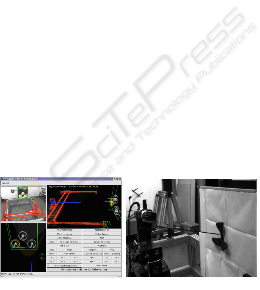
Figure 10: ARITI Application on free form object (toy)
Figure 9: The system interface
A SKELETON BASED METHOD FOR EFFICIENT 3D OBJECT LOCALIZATION - Application to teleoperation
101
