
A NEW PARADIGM FOR SHIP HULL INSPECTION USING A
HOLONOMIC HOVER-CAPABLE AUV
Robert Damus, Samuel Desset, James Morash, Victor Polidoro, Franz Hover, Chrys Chryssostomidis
Sea Grant Autonomous Underwater Vehicles Lab, Massachusetts Institute of Technology, Cambridge, MA, USA
Jerome Vaganay, Scott Willcox
Bluefin Robotics Corporation, Cambridge, MA, USA
Keywords: Autonomous Underwater Vehicle, hovering, feature-relative navigation, inspection
Abstract: The MIT Sea Grant AUV Lab, in association with Bluefin Robotics Corporation, has undertaken the task of
designing a new autonomous underwater vehicle, a holonomic hover-capable robot capable of performing
missions where an inspection capability similar to that of a remotely operated vehicle is the primary goal.
One of the primary issues in this mode of operating AUVs is how the robot perceives its environment and
thus navigates. The predominant methods for navigating in close proximity to large iron structures, which
precludes accurate compass measurements, require the AUV to receive position information updates from
an outside source, typically an acoustic LBL or USBL system. The new paradigm we present in this paper
divorces the navigation routine from any absolute reference frame; motions are referenced directly to the
hull. We argue that this technique offers some substantial benefits over the conventional approaches, and
will present the current status of our project.
1 INTRODUCTION AND
EXISTING CAPABILITIES
The majority of existing autonomous underwater
vehicles (AUVs) are of a simple, torpedo-like
design. Easy to build and control, the torpedo-
shaped AUV has proven useful in many applications
where a vehicle needs to efficiently and accurately
survey a wide area at low cost. As the field of
underwater robotics continues to grow, however,
new applications for AUVs are demanding higher
performance: in maneuvering, precision, and sensor
coverage. In particular, the ability to hover in place
and execute precise maneuvers in close quarters is
now desirable for a variety of AUV missions.
Military applications include hull inspection and
mine countermeasures, while the scientific
community might use a hovering platform for
monitoring coral reefs, exploring the crevices under
Antarctic ice sheets, or close-up inspection in deep-
sea archaeology. An autonomous hovering platform
has great potential for industrial applications in areas
currently dominated by work-class remotely
operated vehicles (i.e., tethered, ROVs): subsea
rescue, intervention, and construction, including
salvage and wellhead operations.
Frequent hull inspection is a critical maintenance
task that is becoming increasingly important in these
security-conscious times. Most ships (whether
civilian or military) are only inspected by hand, in
dry-dock, and thus rarely - certainly not while they
are in active service. Standards do exist for UWILD
(Underwater Inspection in Lieu of Drydock), but
divers have typically performed underwater
inspections, a time-consuming, hazardous job.
Additionally, there is a high probability of divers
missing something important, because it is so
difficult for a human being to navigate accurately
over the hull of a ship, with their hands, and often in
poor visibility. With a loaded draft on the order of
30m and a beam of 70m for a large vessel,
debilitating mines can be as small as 20cm in size,
and in this scale discrepancy lies the primary
challenge of routine hull inspection.
127
Damus R., Desset S., Morash J., Polidoro V., Hover F., Chryssostomidis C., Vaganay J. and Willcox S. (2004).
A NEW PARADIGM FOR SHIP HULL INSPECTION USING A HOLONOMIC HOVER-CAPABLE AUV.
In Proceedings of the First International Conference on Informatics in Control, Automation and Robotics, pages 127-132
DOI: 10.5220/0001145701270132
Copyright
c
SciTePress

The simplest inspection is a visual examination
of the hull surface. Underwater however,
(particularly in harbors and at anchor in coastal
waters) a visual inspection must be performed very
close to the ship. The health of a ship’s skin may
also be judged by measuring plating thickness, or
checking for chemical evidence of corrosion. For
security purposes, a sonar image may be adequate
because of larger target size. For instance, the US
Customs Service currently uses a towfish sidescan
sonar to check hulls (Wilcox, 2003).
Some military vessels are now using small, free-
swimming ROVs for in-situ inspection (Harris &
Slate, 1999). This method eliminates the safety
hazard of diver work, but retains the disadvantage of
uncertain navigation and human load. The only
commercial hull inspection robot, at the time of this
writing, is the Imetrix Lamp Ray. Lamp Ray is a
small ROV designed to crawl over the hull surface.
The ROV is deployed from the vessel under
inspection; the vehicle swims in and closes with the
hull under human control, then holds itself in place
using front-mounted thrusters for suction. The
operator then drives the ROV over the hull surface
on wheels. This limits the survey to flat areas of the
hull; more complex geometry around e.g. sonar
domes, propeller shafts, etc. must still be visually
inspected with a free-swimming ROV. The Cetus II
AUV is an example of a free-swimming autonomous
system that has also conducted ship hull surveys
(Trimble & Belcher 2002). Using altimeters to
maintain a constant relative distance from the hull,
and the AquaMap long baseline navigation system
(DesertStar, Inc.), Cetus II records globally-
referenced position information, and this (with depth
and bearing to the hull) is the primary navigation
sensor used to ensure and assess full coverage. The
AquaMap system uses a transponder net deployed in
the vicinity of the ship being inspected (see URL in
References); clearly, a long baseline acoustic system
could be used for any vehicle.
Our vehicle program has three unique aspects to
address the needs of ship hull inspection:
development of a small autonomous vehicle
optimized for hovering, and of a hull-relative
navigation procedure, wherein dependence on a
deployed acoustic navigation system is avoided.
The data product this vehicle will produce is a high-
resolution sonar mosaic of a ship hull, using the
DIDSON imaging sonar (University of
Washington’s Applied Physics Laboratory) as a
nominal payload (Belcher et al., 2003).
2 PHYSICAL VEHICLE
OVERVIEW
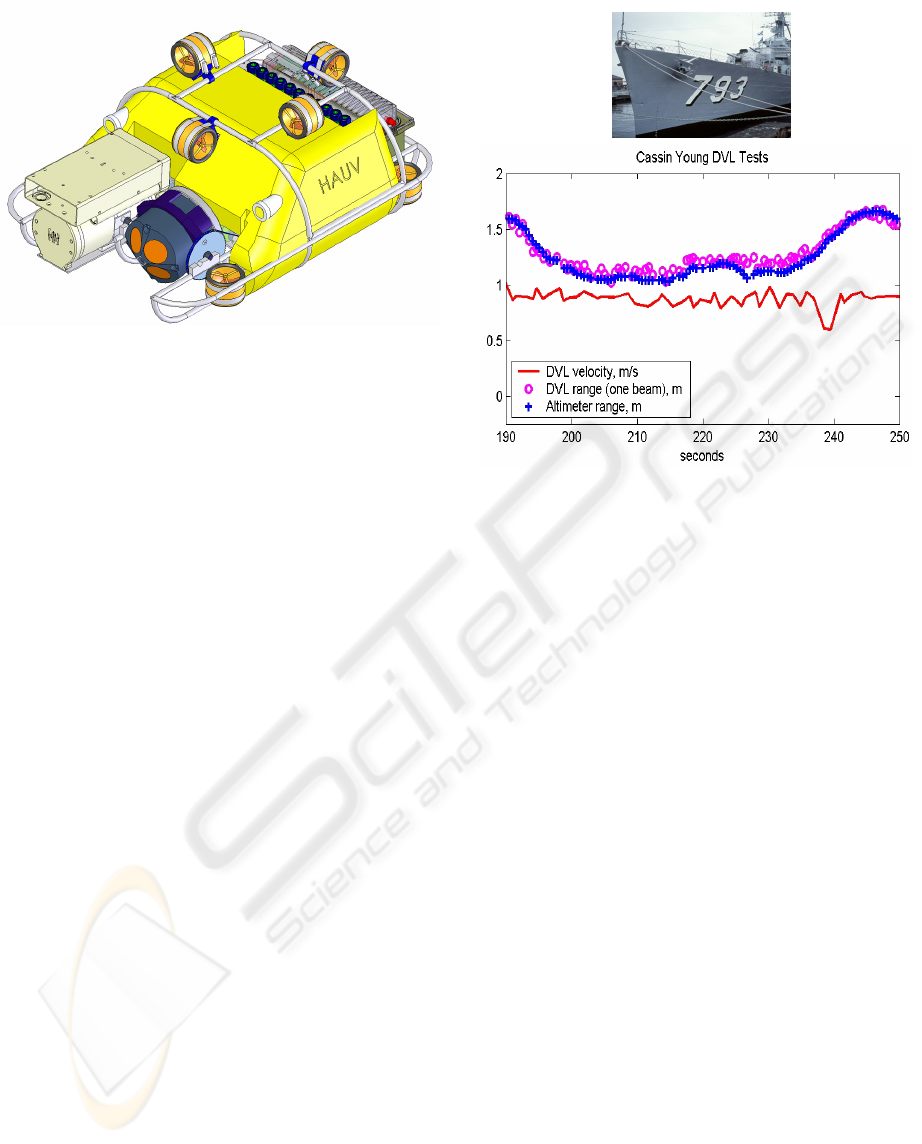
The hovering AUV (HAUV, Figure 1) has eight
hubless, bi-directional DC brushless thrusters, one
main electronics housing, and one payload module.
The symmetrical placement of the large number of
thrusters makes the vehicle agile in responding to
wave disturbances, and capable of precise flight
maneuvers, such as orbiting targets for inspection or
hovering steadily in place. The vehicle is intended
to operate in water depths ranging from the Surf
Zone (SZ) through Very Shallow Water (VSW) and
beyond, up to depths of 100 meters; and to perform
in waves up to Sea State Three.
Onboard non-payload instruments include a
Doppler velocity log (DVL), inertial measurement
unit (IMU), depth sensor, and acoustic modem for
supervisory control. While we do carry a magnetic
compass, this cannot be expected to work well in
close proximity to a metal hull. As noted above, the
nominal payload at this writing is the DIDSON
imaging sonar. Both the DIDSON and the DVL are
mounted on independent pitching servos at the front
of the vehicle, because the DIDSON produces good
imagery at an incidence angle greater than 45
degrees, while the DVL needs to maintain a normal
orientation to the hull. The DVL can also be pointed
down for a bottom-locked velocity measurement.
The vehicle is strongly passively stable, with a
gravity-buoyancy separation of about 3cm. It has
approximate dimensions of 100cm long, 80cm wide,
and 30cm tall; it displaces about 45kg. Of this
weight, about 12kg are for a 1.5kWh battery.
3 OUR APPROACH TO HULL
NAVIGATION
We have chosen to attack this problem from a
feature-relative navigation standpoint, as this has
some advantages compared to current approaches.
Our basic strategy is to measure tangential velocity
relative to the hull being inspected using a Doppler
velocity log (DVL), and to servo a desired distance
from the hull, and orientation, using the individual
ranges from acoustic beams.
The immediate impact of this functionality is the
elimination of support gear for the robot itself; no
localized network setup like LBL is needed. This
reduces complexity and provides a simple, quick
deployment where the robot can operate unattended;
our long-term goal is that the mission focus could
shift towards analyzing the data collected. The lack
of a shipboard system presence also means the craft
ICINCO 2004 - ROBOTICS AND AUTOMATION
128
can be deployed quickly to respond to developing
situations below the waterline.
As a second benefit, the proposed feature-
relative control schemes should work when the ship
being inspected is fixed within a close berth (where
LBL navigation could be poor), anchored and
moving slowly about its mooring, or moving freely
at very low speed, e.g., adrift.
The key technical point to note about navigating
relative to a fixed hull surface is that the vehicle is
constrained absolutely in the DOF normal to the
hull, but not tangentially. A featureless hull is a
poor candidate for visual or sonar image serving,
and the use of DVL velocity measurements for
positioning invokes an obvious drift error over time.
3.1 Suitability of the DVL for this
Task
The DVL (RD Instruments; see URL in References)
comprises four narrow beam transducers, arranged
uniformly at a spread angle of 30 degrees, and
operating broadband in the frequency range of
1200kHz. The Doppler shift is measured for each
beam, and an average sensor-relative tangential
velocity vector is computed. We also have available
the four ranges from the individual transducers: the
device provides range by using the return times from
each sensor and the speed of sound in water.
Complete (four-transducer) measurements are
available at a bandwidth of 3-8Hz, depending on
signal quality and range.
Figure 2: DVL performance when towed along the hull of
the USS Cassin Young
We performed a series of tests with the DVL,
with the specific goal of determining suitability for
the hull-relative inspection task. Specifically, we
have considered: a) what is the drift rate of the
integrated velocities? b) What is the noise
characteristic of the independent range
measurements? c) What is the effect of a metal hull,
with biofouling? d) Does the DIDSON acoustic
imaging system interfere with the DVL?
• On a cement and glass wall at the MIT
Ocean Engineering Testing Tank, the
position error in integrating velocity was
confirmed to be about 0.5 percent of
distance traveled. The error goes up
substantially when the sensor is oriented
more than 30 degrees from normal to the
hull.
• We performed field tests along the hull of
the USS Cassin Young, at the Navy
Shipyard in Charlestown, Massachusetts.
As shown in Figure 2, the range and
velocity measurements are well behaved.
• We performed controlled tests at the
Testing Tank, with simultaneous operation
of the DIDSON and the DVL. DIDSON
images (at 5fps) show the DVL pings as a
Figure 1: The HAUV, showing DIDSON (light
brown) and DVL (dark blue) on the front, yellow
flotation in the mid-body, and a large battery at the
stern. Thruster locations are reconfigurable; the main
electronics housing is underneath the foam
A NEW PARADIGM FOR SHIP HULL INSPECTION USING A HOLONOMIC HOVER-CAPABLE AUV
129
faint flash, but the image is by no means
unusable. Conversely, there is a slight
degradation of the DVL’s velocity
performance. The drift rate approximately
doubles, but remains below 1cm per meter
of distance traveled, which is sufficiently
low enough to satisfy our concept of
operations.
Figure 3: The horizontal slice method; the vehicle makes
passes at constant depth
3.2 Two Approaches Using “Slicing”
The DVL can be used to servo both orientation and
distance to the hull (through the four independent
range measurements) and to estimate the distance
traveled, with reasonable accuracy. When coupled
with an absolute depth measurement, two plausible
inspection scenarios emerge for the majority of a
large ship’s surface: vertical and horizontal
“slicing.” For the purposes of this paper, we
confine our discussion to the large, relatively smooth
surface of the hull sides, bottom, and bow. As with
other existing automated inspection methods, the
stern area with propellers, rudders, shafting and
bosses cannot be easily encompassed within our
scheme.
In the case of horizontal slicing (Figures 3 and
4), paths in the horizontal plane are performed. The
absolute depth provides bounded cross-track error
measurement, while the integrated velocity provides
the along-track estimate of position. This along-
track position, with depth, is recorded for each
image.
Defining the end of a track at a given depth is a
sensing challenge to which we see several possible
approaches. First, there may be landmarks, such as
weld lines, protuberances, or sharp edges as found
near the bow or stern areas. These landmarks,
especially if they occur at many depths, can be used
to put limits on the search area, and to re-zero the
integrated velocity error. Certainly prior knowledge
of the ship’s lines and these features can be
incorporated into the mapping strategy at some
level.
On the other hand, the complete absence of
features is workable also: operate at a given depth
until the integrated velocity safely exceeds the
circumference of the vessel, then move to another
depth. When an object of interest is detected,
immediate surfacing must occur in this scenario
since location along the hull would be poorly
known.
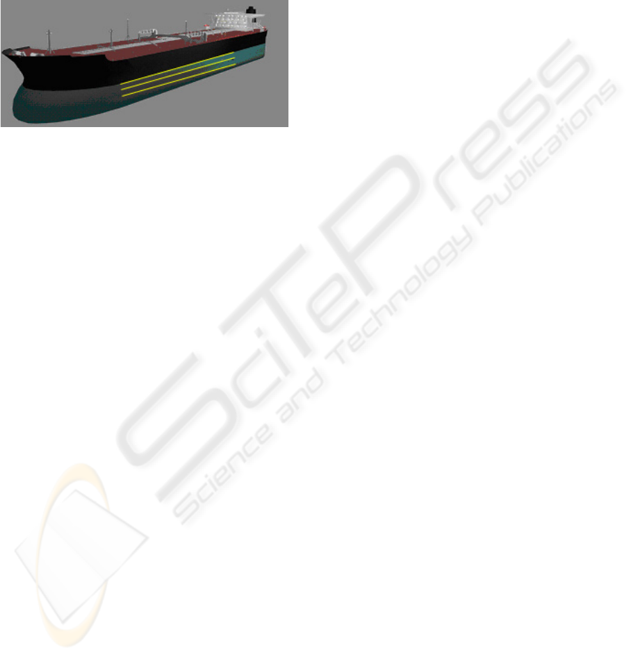
The horizontal slice method is very good for the
sides and bow of a vessel. Many vessels, for
example, large crude carriers (LCC’s) have flat
bottoms, which must also be inspected. Here, aside
from the fact that the vehicle or the imaging sensor
and DVL must be reoriented to look up, there is no
cross-track error available, since the depth is roughly
constant. Long tracks parallel to the hull centerline
would be subject to accrued errors on the order of
several meters. The vertical slice approach (Figure
5) addresses this problem, by making paths down the
sides of the hull and then underneath, in a plane
normal to the hull centerline. Once at the
centerline, options are to turn around and come back
up on the same side, or to continue all the way under
the hull to surface on the other side, after a 180-
degree turn in place (which must be constructed
based on rate gyro information only). In either case,
the important property here is that the path length is
limited, so that the cross-track errors are limited, and
overlap can be applied as necessary. For instance,
using a vertical path length of 130m implies a cross-
track error on the order of 65cm, which is easily
covered by overlapping images with field of view
several meters, assuming no systematic bias.
Convex or concave, two-axis curvature of the
hull also requires some overlap. For instance, in the
extreme case of a spherical hull and the vertical
survey, like ribbons around a ball, the imaged path
lines converge at the bottom. These cases will
require further study and mission design at a high
level.
3.3 Role of Low- and Mid-Level
Control
Dynamically, the vehicle is equipped with high-
performance thrusters so as to operate in shallow
waters, waves, and in proximity to hulls. The
primary sensor we have available, the DVL,
however, is a comparatively low bandwidth device,
which cannot provide robust measurements for
direct control – the noise properties may be
unpredictable, timing may vary, and missed data are
not uncommon. Furthermore, loss of contact with
the hull can occur in regular operation, and even be
exploited as a landmark.
ICINCO 2004 - ROBOTICS AND AUTOMATION
130
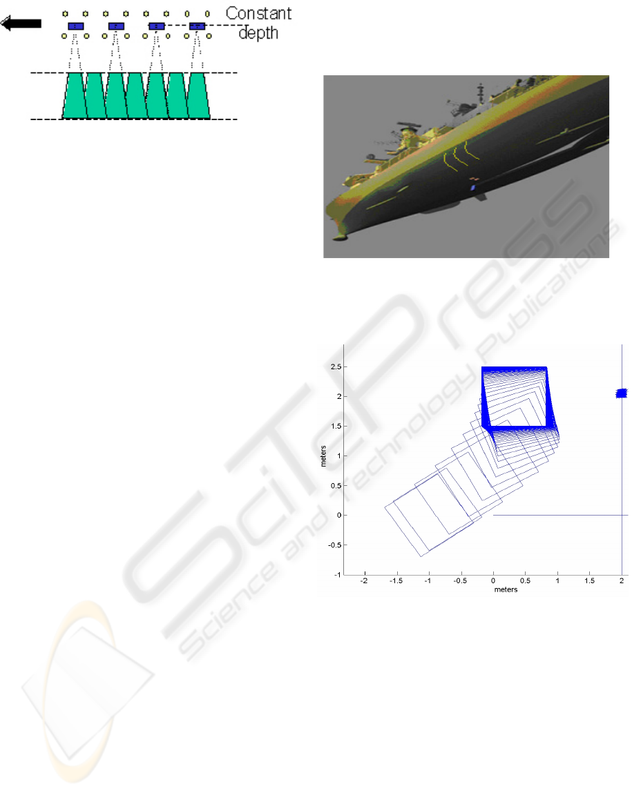
Figure 4: Operation during horizontal survey, looking at
the side of the vessel. The vehicle is shown in blue, with
the four DVL footprints in yellow on the hull. The
DIDSON images (green) are taken looking downward as
the vehicle moves
In waves, the depth sensor also fails as a high-
bandwidth navigation sensor. As a consequence of
these facts, the vehicle has to be capable of short-
term autonomous navigation, through a high-end
inertial measurement unit, and an integrated low-
level control system. The division of control can be
stated as follows: The low-level controller depends
only on the core sensors of the IMU, while a mid-
level layer incorporates the DVL and depth sensor,
and a high-level controller manages the mission and
desired pathlines. This multi-level control system is
to be of the inner-outer loop type, with the DVL and
depth sensor providing setpoints for higher-
bandwidth inner loops. As in most cases of inner-
outer design, the outer loop bandwidth should be at
least 3-5 times slower than the inner loop.
Consider for example the case of yaw control
relative to the hull. At the innermost level, a yaw
rate servo runs at maximum update frequency and
closed-loop bandwidth, employing a model-based
estimator, i.e., a Kalman Filter for handling vehicle
dynamics and sensor channels that are coupled due
to gravity. The mid-level control has coupling, due
to the fact that the DVL is like a velocity sensor on a
moment arm, so that yaw and sway at the wall are
kinematically coupled. This is one of many
concepts from visual servoing that are appropriate
here (e.g., Hutchison et al., 1996). Figure 6 gives
an illustration of hull servoing using nested low- and
mid-level control, and DVL data.
4 SUMMARY
Doppler velocimetry with ranging facilitates a new
feature-relative approach for autonomous ship hull
inspection, one which allows several intuitive
strategies that can account for the majority of the
hull surface. The use of landmarks and ship’s lines,
as well as survey techniques for complex stern
arrangements are still open questions.
Support is acknowledged from the Office of Naval
Research (Dr. T.F. Swean) under Grant N00014-02-
1-0946, and from NOAA and the Sea Grant College
Program, Grant NA 16RG2255.
Figure 5: Vertical slice survey; the vehicle makes depth
passes with zero sway velocity
Figure 6: Example of low- (PID) and mid-level (LQG)
coupled control in the yaw-sway hull positioning problem.
Vehicle initially is at a 42 degree bearing, 3m range; final
position is zero degrees bearing, 1.7m range. The
controller keeps the tangential velocity small while
reorienting, so that the excursion of the DVL “pointer” on
the wall (line on right hand side) is 12cm
REFERENCES
Belcher, E., B. Matsuyama, and G. Trimble, 2003. Object
Identification with Acoustic Lenses.
http://www.apl.washington.edu/programs/DIDSON/M
edia/object_ident.pdf
A NEW PARADIGM FOR SHIP HULL INSPECTION USING A HOLONOMIC HOVER-CAPABLE AUV
131

Harris, S.E. and E.V. Slate, 1999. Lamp Ray: Ship Hull
Assessment for Value, Safety and Readiness. Proc.
IEEE/MTS Oceans.
Hutchinson, S., G.D. Hager, and P.I. Corke, 1996. A
tutorial on visual servo control. IEEE Trans. Robotics
and Automation, 12:651-670.
RD Instruments DVL, http://www.dvlnav.com.
Ship Hull Inspections with AquaMap
http://www.desertstar.com/newsite/positioning/shiphul
l/manuals/Ship%20Hull%20Inspections.pdf.
Trimble, G. and E. Belcher, 2002. Ship Berthing and Hull
Inspection Using the CetusII AUV and MIRIS High-
Resolution Sonar, Proc. IEEE/MTS Oceans.
http://www.perrymare.com/presentations/Oceans%202
002%20Homeland%20Defense.pdf. See also:
http://web.nps.navy.mil/~brutzman/Savage/Submersib
les/UnmannedUnderwaterVehicles/CetusFlyerMarch2
001.pdf.
Wilcox, T., 2003. Marine Sonic Technologies Ltd.,
Personal communication.
ICINCO 2004 - ROBOTICS AND AUTOMATION
132
