
DIMSART: A REAL TIME - DEVICE INDEPENDENT MODULAR
SOFTWARE ARCHITECTURE FOR ROBOTIC AND TELEROBOTIC
APPLICATIONS
Jordi Artigas, Detlef Reintsema, Carsten Preusche, Gerhard Hirzinger
Institute of Robotics and Mechatronics, DLR (German Aerospace Center)
Oberpfaffenhofen, Germany
Keywords:
Telepresence, Distributed Control, Indpendency, Robotic, Telerobotic, DIMSART, RTLinux, VxWorks
Abstract:
In this paper a software architecture for robotic and telerobotic applications will be described. The software
is device and platform independent, and is distributed control orientated. Thus, the package is suitable for
any real time system configuration. The architecture allows designers to easily build complex control schemes
for any hardware device, easily control and manage them, and communicate with other devices with a plug-
in/plug-out modular concept. The need to create a platform where control engineers/designers could freely
implement their algorithms, without needing to worry about the device driver and programming related issues,
further motivated this project. Implementing a new control algorithm with the software architecture described
here, requires that the designer simply follow a template where the necessary code is reduced to only those
functions having to do with the controller. We conducted several teleoperation schemes, one of which will be
presented here as a configuration example.
1 INTRODUCTION
Control methods are nowadays totally related to soft
computing techniques. From this relationship a new
area in software engineering is emerging, which ex-
plores the interplay between the control theory and
software engineering worlds. It is in this research di-
rection that the authors found the need of building a
robotic control software architecture. Among other
things, the architecture should facilitate the develop-
ment of robotic and telerobotic control schemes by
defining beneficial constraints on the design and im-
plementation of the specific application, without be-
ing too restrictive. Keeping this goal in mind, the
DIMSART has been developed by the Telepresence
group of the Institute of Robotics and Mechatronics
to provide a practical, convenient and original solu-
tion.
1.1 Telepresence Environment
The focus of the DIMSART is the development of
Telepresence systems. Telepresence is an extension
of the telerobotics concept in which a human operator
is coupled with as much sensory information as possi-
ble to a remote environment through a robot, in order
to produce an intuitive and realistic interaction with
that environment. The range of senses can encom-
pass vision, tactile, auditory, and even smell and taste
senses. Our interest is focused on the haptic chan-
nel, therefore the type of information which is sent
is motion and force data. From the control point of
view, such systems are often referred to as bilateral
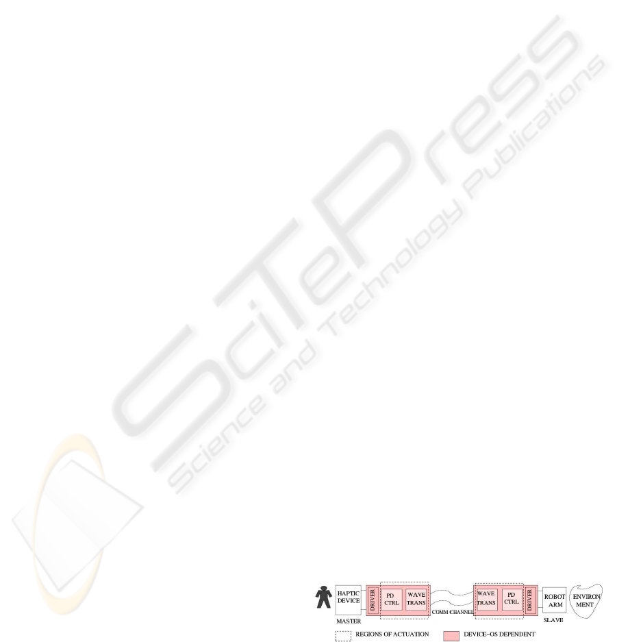
control schemes (see fig.1), because two controls are
simultaneously performed in the telepresence global
closed loop, one on the master side (controlling the
master device), and one on the slave side (controlling
the slave device).
Figure 1: Telepresence Scheme
A telepresence system developed by the Telepres-
ence research group from DLR Oberpfaffenhofen will
be used in this article to show the needs and require-
ments of the architecture, and thus, motivate the de-
velopment of the DIMSART to the reader. Its extrap-
olation to ”mono-lateral” robotics applications will be
straightforward.
102
Artigas J., Reintsema D., Preusche C. and Hirzinger G. (2004).
DIMSART: A REAL TIME - DEVICE INDEPENDENT MODULAR SOFTWARE ARCHITECTURE FOR ROBOTIC AND TELEROBOTIC APPLICATIONS.
In Proceedings of the First International Conference on Informatics in Control, Automation and Robotics, pages 102-109
DOI: 10.5220/0001147301020109
Copyright
c
SciTePress
1.2 Control and Software
engineering Interplay
A not less significant goal is the creation of an har-
mony between the computer science world and the
control engineering world. Not rarely, control engi-
neers are faced with obstacles arising from the pro-
gramming work required for controlling and driv-
ing hardware devices. The software architecture de-
scribed here allows a control engineer to forget about
issues related to device drivers, real time program-
ming, concurrencies or thread programming. Thus,
he/she only needs to concentrate on the specific con-
trol algorithm. As it will be seen, by using this
software platform, the designer is only faced with
the creation a ”module”, for which a template-based
methodology is used. This goal will result in a pro-
gramming time saving for the control designer and
thus the consequence of investing the whole energy
in the control design itself.
1.3 Existing Architectures
The generalized needs of facilitating efficient robotic
system designs and implementations resulted in
the development of several software architectures.
In (
`
Eve Coste-Mani
`
ere and Redi Simmons, 2000)
these general needs are formalized. Furthermore, the
importance of making the right architecture choice
is noted, and some architectures are compared and
contrasted.
Some architectures for robotic systems are very
complete packages which consider the overall struc-
ture for controlling a robot, including all possible
levels of competence in a robotic system (sensing,
mapping, modeling, planning, AI, task execution,
motor control, etc...) either in a hierarchical layered
style (Albu et al., 1988), in a behavioral one (Brooks,
1986), or in an hybrid one (Borrelly et al., 1998),
(Schneider et al., 1998), (RTI, 2004), (Volpe et al.,
2001). However these kind of architectures are more
appropriate for autonomous robot vehicles where
a control at high level or, alternatively, a Decision
Layer, as mentioned in (Volpe et al., 2001), is of high
importance.
Other architectures are not so concerned with
layered structures and emphasize instead the real
time operation as a sequence of control components
executed at a lower level. These architectures tend to
be simpler but more flexible (Scholl, 2001), (Stasse
and Kuniyoshi, 2000).
The DIMSART architecture shines for its simplic-
ity, flexibility and portability. It can be included to the
second group of architectures, but it is more focused
in the automatic control level. Furthermore, it can
be easily embedded in other architectures or systems
with almost any Linux/Unix operating system type:
Linux, Solaris, RTLinux, VxWorks.
The outline of this paper is as follows. We first
present, in section 2, a chapter dedicated to general
robotic control concepts with a particular scheme ex-
ample which will be used in the subsequent sections
to introduce the DIMSART architecture. We then de-
scribe the software platform and its main parts in sec-
tion 3. Section 4 introduces a complete experimen-
tal setup as a DIMSART configuration example. Fi-
nally, in section 5, some concluding remarks and fu-
ture lines are given.
2 ROBOT CONTROL
We will make use of a telepresence control scheme
example to focus our interest in three aspects: dis-
tributed control, the data flow and the definition of the
acting regions of our framework. Also in this chap-
ter, a more abstract view of a general robotic control
scheme will be introduced, and later it will be speci-
fied within the mentioned example.
2.1 Wave Variables Scheme as
Bilateral Control Example
In fig.2 a block diagram of a Wave Variable control
scheme can be seen. The Wave Variables Theory
is a common approach to minimize the degradative
effects of time-delayed communication channels
in telepresence systems. For detailed information
about this theory refer to (Niemeyer, 1996) and
(Artigas, 2003) . It is not the aim of this paper to
detail the control theory behind the scheme. Rather,
it is intended to be used as a reference point for the
DIMSART approach. We will refer to this example
in some of the following sections to give support to
the theoretical explanations of the architecture.
Figure 2: Global control software is decoupled from hard-
ware device, driver and communication
DIMSART: A REAL TIME - DEVICE INDEPENDENT MODULAR SOFTWARE ARCHITECTURE FOR ROBOTIC
AND TELEROBOTIC APPLICATIONS
103
Distributed Control
In telepresence scenarios the concept of distributed
control becomes an important issue. Although from
the hardware point of view both master and slave de-
vices can be quite different, from the control point of
view they are not so dissimilar. The main idea of dis-
tributed control is to divide the global control task of
the system in n identical or quasi identical local con-
trol components. The nature of a bilateral control is
to distribute the control task between both sides, mas-
ter and slave. The control component, -henceforth re-
ferred to as module-, will have to be sufficiently pow-
erful to support
1. The existing differences between master and slave
robots/environments characteristics (for instance,
controller constants, input/output variables, algo-
rithm differences, etc...)
2. Possible different OS platforms. For example, the
master could be controlled by a RTLinux machine,
and the slave by a VxWorks one.
In our bilateral control scheme, the control task is
distributed between master and slave sides through
the Wave Transformer and PD Controller blocks.
Main operation and Data Flow
The two blocks on each side of the system in
fig.2, PD Controller and Wave Transformer, can be
viewed, from the software point of view, as a chain of
algorithms with similar characteristics sequentially
called. This reasoning leads to an object-oriented
direction, in which a Module Template class can be
constructed and from which different objects (the
control elements) can be defined. Modularity will
facilitate a Top-down design methodology, as well as
code reuse.
Defining operating boundaries
By defining the operating boundaries shown in
fig.2, the independence from the hardware driver and
the communication channel will be preserved, or, in
other words, the control task will be uncoupled (from
the software point of view) from the rest of the sys-
tem. Portability and independence are direct conse-
quences. That is, portability to other robotic systems
can be achieved, independently of the robot and com-
munication channel.
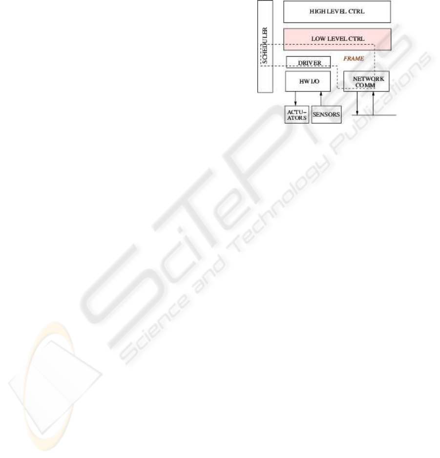
2.2 General Robot Control setup
Fig.3 skews the components of a general robotic sys-
tem. On the lowest level, we find the sensors and ac-
tuators of the haptic/robot device. The driver, which
is in charge of initializing and closing the device, and
reading and writing data from/to it, is part of what
we call the frame. The frame encompasses elements
located between the low level control layer, the hard-
ware I/O layer and the network communication layer.
The high level control layer deals with non-real time
control such as task planning or behavioral control.
Our framework will be focused on the low level con-
trol layer and its relationship with the frame.
Figure 3: Components of a general robot control setup
Some of the tasks of the frame include the commu-
nication between the software architecture, the hard-
ware device and the network, and the real time read-
ing, processing and writing scheduling. The fol-
lowing code exemplifies the master’s main operation
of the example depicted in fig.2 for a mono-thread
frame:
dev_open(&Phantom);
dev_init(&Phantom);
main_interrupt_thread(arg){ /*called every 1 ms*/
/* Some inis*/
Read_Comm(in_waves);
Robot_read(local_pos);
/*---------- Control ---------*/
exec_PDctrl(local_pos,
prev_des_pos,
out_force);
exec_WaveTrans(in_waves,
out_waves,
des_pos);
/* context save:*/
prev_des_pos=des_pos;
/*----------------------------*/
Write_Comm(out_data);
Robot_Command(force);
}
dev_close(&Phantom);
Often, the low level controlling task is performed
by the same frame in the real time main interrupt.
However, defining the boundaries indicated in fig.2,
and thus isolating the control task from the rest of the
system, would bring significant benefits. The DIM-
ICINCO 2004 - ROBOTICS AND AUTOMATION
104
SART architecture provides the needed mechanisms
for this job.
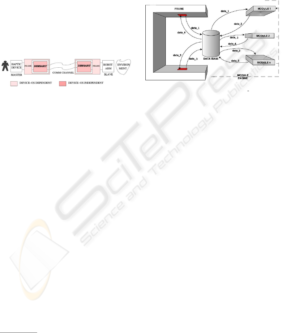
2.3 Bilateral Control Scheme with
DIMSART embedded
At this point, we are ready to concretely define
specific requirements for the architecture, as well
as its location in a robotic scheme. Fig.4 shows
the introduced bilateral control example with a
DIMSART on each side. Each DIMSART performs
the control for each side and could be running in
different operating systems.
Figure 4: Bilateral control scheme with two DIMSART: one
on the master side, one on the slave side.
Requirements
1. OS independency.
2. Device independency. This implies that the archi-
tecture can be set for any DoF
1
, I/O data types and
sampling rate.
3. Modular. Permits a Top-down control scheme de-
sign methodology. Flexibility upon the design.
4. Dynamic. Only one compilation must be needed
to construct any control scheme configuration.
5. Must allow distributed control.
3 ARCHITECTURE OVERVIEW
The DIMSART can be defined as a real time device
independent software architecture for distributed con-
trol in robotic and telerobotic applications. The cen-
tral point of the DIMSART consist of a dynamic Data
Base. Around the Data Base, there is a frame and
modules. These two kind of elements interact with
the Data Base by writing data to it or reading from
it. A module, which implements a specific control al-
gorithm, gets its input from the Data Base and writes
its output to it. The device driver (frame) also reads
and writes from and to the Data Base in a similar
manner. The modules are sequentially called by a
Module Engine and transform the input data to
produce their output. The following subsections de-
scribe each element mentioned above. Fig.5 is a block
1
DoF: Degrees of Freedom
diagram of the DIMSART overview. Furthermore, in
a higher layer, a GUI has been developed to configure
the robotic control scheme. The user can choose from
a list of read-to-use modules which ones to activate,
and configuration parameters can also be set for each
module.
Figure 5: DIMSART Concept Diagram. ”data x” stands for
data types.
3.1 Modules
In this framework, a Module is a piece of software
intended to perform real time operations. As already
mentioned, the module is the data processing unit of
the DIMSART. The range of possible functionalities
of a module is quite wide. Some examples are control
algorithms such as P, PD, PID controllers for robots
or haptic devices; simulation of an environment
such as a virtual wall; a magnitude converter such
as a data normalizer for sending data through a
network; a numerical integrator or derivator such as a
velocity-to-position converter; a wave transformer as
the one shown in fig.2.
There are two types of data with which the Module
interacts: internal local data, which stores config-
uration parameters of the module and is located in
the same module, and the data to process, which
is stored in the Data Base. The real time main op-
erations of a module can be synthesized in three steps:
1) Read: read data from the Data Base.
2) Compute: process the data to perform the control.
3) Write: write the output data to the Data Base.
The type or types of data which the module
extracts from the Data Base, and later the types to be
written, are defined in its activate function. There,
the module tells the Data Base the data type or types
which need to be read, and the type or types which
are to be written.
DIMSART: A REAL TIME - DEVICE INDEPENDENT MODULAR SOFTWARE ARCHITECTURE FOR ROBOTIC
AND TELEROBOTIC APPLICATIONS
105
Moreover, as it will be seen in section 3.3, the
Module Engine provides a mechanism for com-
municating with the active modules. By means of
a Command interface, the user will be able to send
commands from the frame space to a specific mod-
ule. These commands are internally defined in the
module, and they are thought to set the configuration
parameters of the module (in the previous example, a
Command could be used to set the constants of the
PD Controller, or to specify the configuration of the
Wave Transformer).
Once the DIMSART is loaded in a robotic system,
any control engineer can easily implement a module
by simply following a module pattern in a pure ”write
your code here” style. The aim of the DIMSART is to
create a list of modules, from which control engineers
will be able to build complex control schemes by
choosing and combining modules from this list.
Thus, a chain or sequence of modules will be created
to perform the control task of a robotic application.
As it will be seen in the following subsections, after
a module ”library” is created, the user will be able to
activate and deactivate modules in a plug-in/ plug-out
methodology.
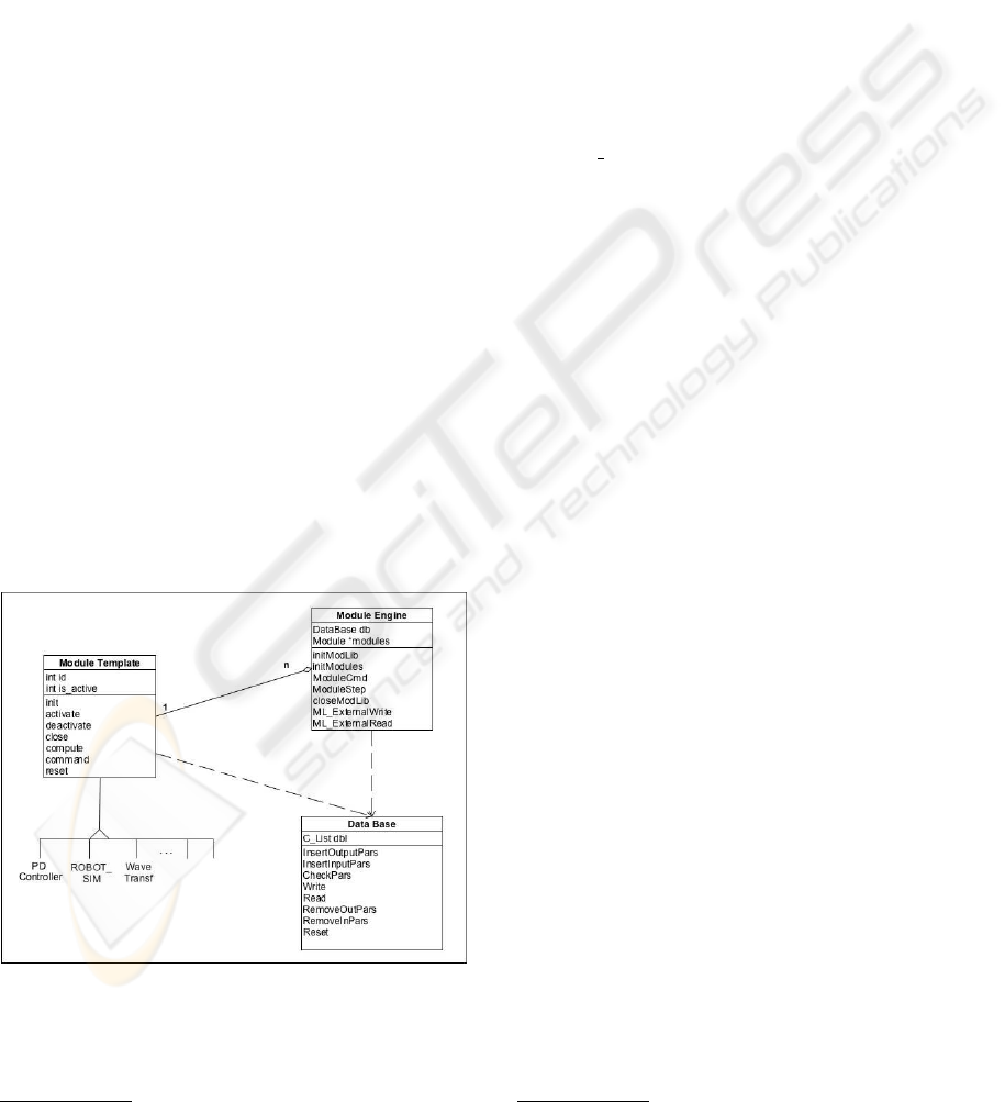
Module Template
As already stated, every control block has simi-
lar characteristics. The Module Template formalizes
the base of every module in an object oriented way.
The class
2
struct Module is declared here with a
group of functions and some attributes (see fig.6).
Figure 6: Class-like Diagram of the DIMSART
2
Simulated class in C code
3.1.1 Initialization and Activation
Initialization of a module means that its internal
memory is allocated, and its internal variables and
constants are initialized. This process takes place
for every module belonging to the modules list
(attributed in the Module Engine, see fig.6),
during the initialization process of the DIMSART.
On the other hand, only the desired modules
for the specific control scheme will be activated.
Activate means to insert the input and output data
types needed by the module under consideration into
the Data Base. Thus the Data Base will dynam-
ically grow by means of each module activation.
The Module Engine, or more precisely, the
Module
Step function (which will be called at
every time step), will act by calling the Compute
function of each active module.
It is important to note the differences between the
tasks of the initialization and activation processes. In
order to make the DIMSART compatible with most
operating systems, the conception of these initial pro-
cesses is based on a kernel/modules
3
model of op-
erating systems like Unix or Linux (Corbet, 2001).
A kernel module in RTLinux, for instance, allocates
its memory during its insertion process. Once the
RTLinux module is inserted it should not allocate
more memory.
3.2 The Data Base
The core of the Data Base is a dynamic list which
stores the incoming data from each active module,
and the data coming from the frame (which comes
from the hardware device). Furthermore, the Data
Base incorporates a set of mechanisms for the data
interaction between the active modules and the
dynamic list. Its construction is performed during the
initialization of the Module Engine and at each
module activation processes.
During the initialization the dynamic list is created
according to a Device Descriptor of the hardware
device. In this descriptor, characteristics such as the
DoF and input and output data types are enclosed.
After the initialization process, the Data Base is
created. At this point, each time a module is activated
new data fields are created in accordance with the
data types needed by the module. Modules can
be inserted or removed at any time during system
operation (which in turn will insert or remove input
and output types into the Data Base).
3
Unix/Linux kernel modules
ICINCO 2004 - ROBOTICS AND AUTOMATION
106
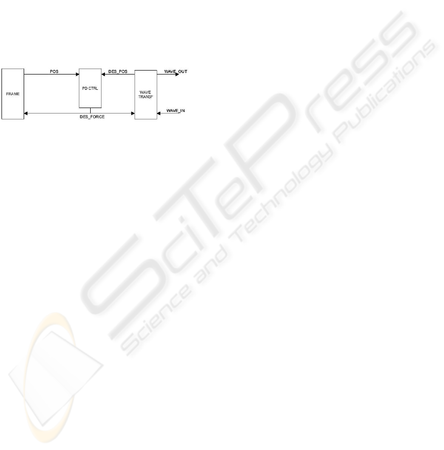
Types Matching Check
The matching check function performs a test to val-
idate the coherency of the relationship between the in-
put and output types of a constructed scheme. Fig.7
presents a closer view of the master side of the ex-
ample in section 2.1. It shows the data interactions
between the blocks in the master side. The PD Con-
troller, for instance, requires position and desired po-
sition as data inputs and outputs desired force. After
the scheme is constructed, the Types matching check
ensures that some other module provides the required
data. In our example, the Wave Transformer provides
desired position to the PD Controller, and the frame
position.
Figure 7: Detailed view of the control scheme in the master
side
3.3 The Module Engine
The Module Engine is the software layer between
the driver and the Data Base and modules. Through
it, a set of capabilities are provided to control and
schedule the engine of the DIMSART from the
frame. A description of the main functionalities
and attributes follows. Refer to fig.6 to locate each
function and attribute described here.
Frame Descriptor: The frame provides to the
Module Engine a descriptor of the robot in the
Module Engine initialization function. This
descriptor contains information about the DoF of
the device, number of input and output data types,
and which types are needed by the device. With
this information, the Module Engine initializes
the Data Base.
List of Modules: During the initialization step, a list
of modules is created with all the included mod-
ules in the DIMSART software architecture from
which, the user chooses which ones to activate.
Module Step: This is the beating heart of the
Module Engine. This is the function that the
main loop of the frame calls at every time step. The
Module Step sequentially calls the Compute func-
tion of each activated Module. This is how each
one of the activated modules performs its real time
computation.
Module Command: An interface to send commands
to the DIMSART from the frame space is also pro-
vided in the Module Engine. A command can
be sent to the Module Engine, or to a specific
module as seen in section 3.1. By sending com-
mands to the Module Engine, the user will be
able to set the configuration of the control scheme.
Some of the most representative commands are the
activation and deactivation of a module, the reset
of a module, or the initialization or the close of the
DIMSART.
Frame Communication: The hardware driver or a
user space (the frame) communicates with the Data
Base in a similar way as the modules do. These
communication mechanisms are also provided in
the Module Engine.
3.4 The Frame
The frame, as indicated in section 2.2, is a space
which joins elements belonging to the hardware de-
vice communication, to the network communication,
and to the DIMSART architecture. The main func-
tions of a frame are outlined here.
- Initialization of the hardware device.
- Initialization of the DIMSART.
- Interaction with the Data Base.
- Call of the Module Step (see sec. 3.3) in every
time step.
- Close the DIMSART.
- Close the hardware device.
The initialization of the DIMSART needs to know
the device characteristics. This is done through the
Device Descriptor (defined in the frame), in which
the following data is enclosed: number of degrees of
freedom of the device; input data types needed by
the frame, which is the data to be commanded to the
device; and output data types, which is the data to be
processed by the active modules in the DIMSART.
The interaction with the Data Base is the read and
write mechanisms for the frame. Two ”external” func-
tions are provided for this purpose. To review the
above concepts, the following code corresponding to
the example presented in section 2.1, shows how a de-
vice driver with a DIMSART embedded should look
like.
init_funct(DevDescr){
dev_open(&Phantom);
dev_init(&Phantom);
initModLib(&DevDescr); /*ini DataBase*/
initModules(&initarg); /*ini all mods*/
cmd.ModNr=MOD_ENGINE;
cmd.ParamNr=MOD_ON;
DIMSART: A REAL TIME - DEVICE INDEPENDENT MODULAR SOFTWARE ARCHITECTURE FOR ROBOTIC
AND TELEROBOTIC APPLICATIONS
107
cmd.Value=PDctrl;
ModuleCmd(&cmd); /*Activates PD ctlr*/
/*Other mod activations go here*/.
}
main_interrupt_thread(arg){
/* Some inis */
Read_Comm(inwaves);
Robot_read(pos);
DB_ext_write(pos,inwaves);
Module_Step(); /*compute active mods*/
DB_ext_read(force,outwaves);
Write_Comm();
Robot_Command(force);
}
DB
ext write : Writes the device output data to the
Data Base (position in the example).
Module Step : function which schedules all active
modules (in the previous example the compute
function of the modules PD Controller and Wave
Transformer are called).
DB ext read : Reads the device input data from the
Data Base (desired force in the example.)
The data coming from the robot is no longer in the
driver, but instead in a data container, from which
other elements will be able to read. Thus, a software
boundary between the frame and the DIMSART is de-
fined.
4 EXAMPLE
Fig.8 shows the complete scheme for the above pre-
sented Wave Variables scheme example, and table
1 its Commands configuration. The system is dis-
tributed within two computers, each one running a
DIMSART architecture. The computer governing the
master is equipped with a RTLinux OS. The slave
runs under Linux. On the master side there is a frame
driving a PHANToM 3DoF (Massie and Salisbury,
1994) as a master device with a DIMSART configura-
tion. The communication between master and slave is
performed through UDP sockets . On the slave side, a
user frame governing a DIMSART is used to simulate
a slave robot and a virtual environment. This specific
scheme was built for testing the performance of the
Wave Variables control scheme as well as for verify-
ing the modular container approach of the DIMSART.
As it can be seen, the communication between the
two sides is performed through some dedicated mod-
ules. These two modules provide the interface be-
tween the DIMSART and the communication chan-
nel.
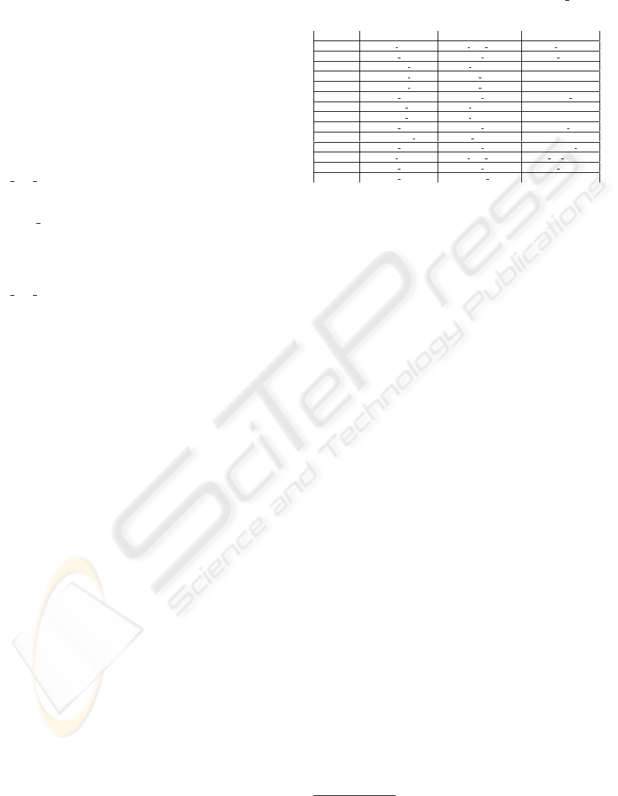
Table 1: Master and slave Commands configuration. Dest
is destination. m&s means master and slave. MOD
ON, for
instance, activates the module.
Dest. Module Command Value
m&s COMM RXMOD CRX ADD DATA CH2 WAVES
m&s MOD ENG MOD ON COMM RXMOD
m&s WTRANSF MOD B PARAM 10
master WTRANSF MOD CONF MODE MASTER
slave WTRANSF MOD CONF MODE SLAVE
m&s MOD ENG MOD ON WTRANSF MOD
master PDCTRL MOD K PARAM 3000
slave PDCTRL MOD K PARAM 5000
m&s MOD ENG MOD ON PDCTRL MOD
master TIMEDELAY MOD TD PARAM 10
master MOD ENG MOD ON TIMEDELAY MOD
m&s COMM TXMOD CTX ADD DATA CH1 TD WAVES
m&s MOD ENG MOD ON COMM TXMOD
m&s MOD ENG MATCHING CHECK /
5 CONCLUDING REMARKS AND
REMAINING ASPECTS
The DIMSART has been presented in this pa-
per. It provides a solution to embed a robotic or
telerobotic control scheme in a hardware device-
OS-communication channel configuration. Indepen-
dence, distributed control, dynamics and flexibility
are values provided to the architecture. The system
performance depends on several parameters which
may vary in every particular scheme. The number of
degrees of freedom, the number of active modules
and the length of the active modules influence the
system performance. The system has been tested
in several robotic and telerobotic contexts and has
shown good performance. One of them has been
presented in this paper as an example and as a tool to
describe the DIMSART architecture to the reader. A
very representative application is the ROKVISS
4
, a
Telepresence experiment in which a force feedback
joystick on Earth is to be controlled with the DIM-
SART architecture, and a 2 DoF robot, which will be
mounted on the ISS is also to be controlled with the
same architecture. For detailed information about the
ROKVISS experiment see (Preusche et al., 2003).
Future work for DIMSART will include several as-
pects. ”Online” module compilation and the exten-
sion of the Data Base to multiple data formats and
dimensions are issues which are already being devel-
oped. Future lines could extend the DIMSART to
high level control and multi-thread architectures.
4
Robotic Component Verification on the International
Space Station (ISS)
ICINCO 2004 - ROBOTICS AND AUTOMATION
108
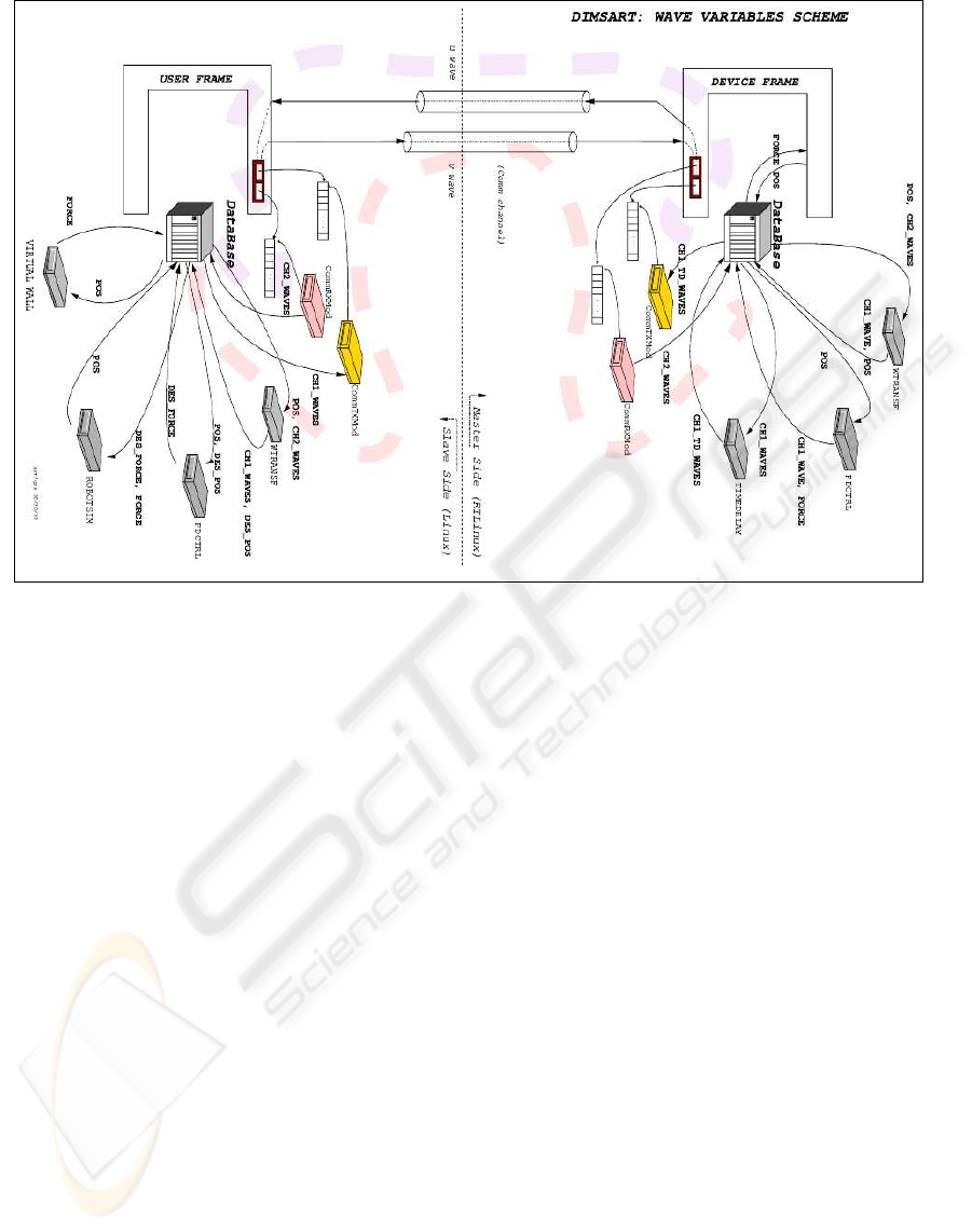
Figure 8: A real bilateral DIMSART setup
REFERENCES
Albu, J., Lumia, R., and McCain, H. (1988). Hierarchical
control of intelligent machines applied to space station
telerobots. Transactions on Aerospace and Electronic
Systems, 24(24):535–541.
Artigas, J. (2003). Development and implementation of
bilateral control using the wave variables therory in
the rokviss experiment. Internal publication, DLR
(German Aerospace Center) - Insitute of Robotics and
Mechatronics.
Borrelly, J.-J.,
´
Eve Coste-Mani
`
ere, Espiau, B., Kapellos, K.,
Pissard-Gibollet, R., Simon, D., and Turro, N. (1998).
The orccad architecture. The International Journal of
Robotics Research, 17(4):338–359.
Brooks, R. A. (1986). A robust layered control system for a
mobile robot. IEEE Journal of Robotics and Automa-
tion, 2(1):14–23.
Corbet, A. R. . J. (2001). Linux Device Drivers, 2nd Edition.
Number 0-59600-008-1.
`
Eve Coste-Mani
`
ere and Redi Simmons (2000). Architec-
ture, the backbone of robotic systems. In Proceed-
ings of the 2000 IEEE International Conference on
Robotics and Automation, San Francisco, CA.
Massie, T. and Salisbury, J. (1994). The phantom haptic in-
terface: A device for probing virtual objects. In Pro-
ceedings of the ASME International Mechanical En-
gineering Congress and Exhibition, pages 295–302,
Chicago.
Niemeyer, G. (1996). Using Wave Variables in Time De-
layed force Reflecting Teleoperation. PhD thesis, Mas-
sachussetts Institute of Technology.
Preusche, C., Reintsema, D., Landzettel, K., and Hirzinger,
G. (2003). Rokviss - towards telepresence control in
advanced space missions. In Humanoids 2003 - The
Third IEEE International Conference on Humanoid
Robots, Munich, Karlsruhe (Germany).
RTI (2004). Constellation. www.rti.com/products/ constel-
lation/index.html.
Schneider, S. A., Chen, V. W., Pardo-Castellote, G.,
and Wang, H. H. (1998). Controlshell: A soft-
ware architecture for complex electromechanical sys-
tems. The International Journal of Robotics Research,
17(4):360–380.
Scholl, K.-U. (2001). MCA2 (Modular Controller Architec-
ture). Software platform. http://mca2.sourceforge.net.
Stasse, O. and Kuniyoshi, Y. (2000). Predn: Achieving effi-
ciency and code re-usability in a programming system
for complex robotic applications. In Proceedings of
the 2000 IEEE International Conference on Robotics
and Automation, San Francisco, CA.
Volpe, R., Nesnas, I., Estlin, T., Mutz, D., Petras, R., and
Das, H. (2001). The claraty architecture for robotic
autonomy. In 2001 Aerospace Conference IEEE Pro-
ceedings, pages 1/121–1/132.
DIMSART: A REAL TIME - DEVICE INDEPENDENT MODULAR SOFTWARE ARCHITECTURE FOR ROBOTIC
AND TELEROBOTIC APPLICATIONS
109
