
WIRELESS REMOTE MONITORING SYSTEM WITH
FLEXIBLY CONFIGURABLE MULTIVISION
Shinichi Masuda, Tetsuo Hattori
Graduate School of Enginieering, Kagawa University, Takamatsu City, Kagawa, 761-0396 Japan
Keywords: Wireless remote monitoring, Multivision, Wireless sensor with ID, Event driven, Infrared camera
Abstract: Novel remote monitoring system for all day outdoor observation using wireless communication is
proposed. It consists of three parts: a host station that is PC, remote station (camera and CPU) attached by
solar cell and battery for power supply, and wireless sensor with ID (identification) signal. The remote
station usually performs based on the event driven method by the sensor signal. It also can control the
camera according to the sensor’s ID. So the multivision monitoring system is flexibly configurable. This
paper describes the details of the system and evaluates the maximum number of connectable remote
stations. Since the systems are now really running at many places in Japan, we consider that the fact shows
its effectiveness in a practical sense.
1 INTRODUCTION
Recently, the necessity of monitoring camera system
has increased in a wide variety of fields. And the
image processing research for such monitoring
system has been done in many ways (
K.Yamada, et al.,
2000), (T.Sogo, et al., 2000), (H.Mori, et al., 2001),
(H.Nagahara, et al., 2001).
The purpose of this kind of
vision system is not only for security against crime
and disaster in the social and individual life, but also
for investigation and control such as of vehicle
traffic. In some of those monitoring camera systems,
especially in outdoor system, the capability of all day
and all weather monitoring with self-feeding of
electric power is required. Moreover, the flexibility
of configuration and installation of multiple cameras
(multivision system) is also required, depending on
the place to be observed.
In this paper, we present a compact wireless
remote monitoring system that we have developed in
order to meet the demands in outdoor monitoring
system. The system is composed of three parts: host
computer (PC) that we call base station, CPU built-
in monitoring camera and the peripherals that we call
remote station, and wireless sensors that are
independent of the monitoring camera. The system
has the following features.
The remote station is made as a self-feeding
system, mainly using solar battery for power supply.
By the wireless communication of portable handy
phone, etc., acquired images at the remote station are
transmitted to the base station.
With all weather and darkness, the camera in
the remote station can acquire images using the
functions of auto focus, auto iris, lens zooming, and
night vision. The camera automatically changes into
an infrared one, depending on the lightness.
Usually based on the wireless sensor’s signal,
the remote station is driven to work. That is, as soon
as one of the wireless sensors detects some object
such as human body, it sends a radio signal to the
remote station, then the station inputs image and
transmits it to the base station.
Because each wireless sensor sends the
discrimination radio signal (or radio ID signal) to the
remote station, the station can control the viewpoint
of camera according to the signal. Then, using those
wireless sensors, it is expected that multi remote
stations are easily composed as a multivision system
with arbitrary configuration for various purposes
such as cooperative tracking.
484
Masuda S. and Hattori T. (2004).
WIRELESS REMOTE MONITORING SYSTEM WITH FLEXIBLY CONFIGURABLE MULTIVISION.
In Proceedings of the First International Conference on Informatics in Control, Automation and Robotics, pages 484-487
DOI: 10.5220/0001147804840487
Copyright
c
SciTePress
2 SYSTEM
2.1 Outline
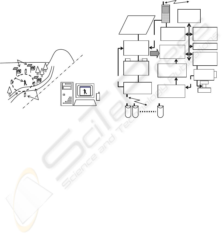
The monitoring system is composed of base station,
remote station, and wireless sensors, as shown in
Figure 1. The remote station usually takes rest state
and it runs according to the wireless sensor’s signal,
that is, it drives and makes the camera acquire
images, and then it transmits the compressed image
data to the base station. After this series of
operations, the remote station automatically takes a
rest state again. The remote station also supplies the
power to the infrared light when it runs at night. It is
possible to force the remote station to run or to rest
by a command signal from the base station.
Figure 1: Conceptual image of the system.
The remote station can continuously keep running
for 5 days using built-in battery, even if there is no
power supply from the solar cell. The wireless sensor
has also a built-in battery, and it keeps working for 2
years. One base station can control a maximum
number of 256 remote stations. And one remote
station can distinguish a maximum number of 16
wireless sensor signals. The wireless sensor’s signal
is effective within approximately 200 meters far
from the remote station. Each wireless sensor can
send the radio ID signal, so the remote station can
operate depending on the ID signal. Then, the
multiple remote stations can work cooperatively. For
example, they can also acquire images of one object
from many directions at the same time.
2.2 Remote Station
Since the multiple remote stations can take images in
many different ways such as synchronous or
asynchronous acquisition, according to the
configurations in the area to be monitored, we can
flexibly construct various multivision monitoring
system. The block diagram of the remote station is
shown in Figure 2.
The remote station is excellent in portability
and is easily installed. After the remote station is put
at some place, the base station can tune up the
precise viewpoint of camera and lens zooming, etc.,
because the base station can easily control the remote
station by wireless communication.
Figure 2: Block diagram of the remote station.
2.3 Performance of Remote Station
As aforementioned, the Built-in microprocessor
(CPU) in the remote station recognizes the wireless
sensor’s ID signal, and take a series of actions:
image acquisition, image data compression, image
transmission, etc. The storage battery in the station
stores electric power by solar energy and supplies it
when necessary.
The specification of the remote station is as
follows.
・Battery:
12V, 15Ah.
・Solar cell:
16.3V, 1.65A/24W.
・Continuous working period without sunlight:
5 days guaranteed.
・Unit box:
Dust and water proof.
Size [mm]: W270×H310×D200×2.
Weight [kg]: Approximately 13kg×2.
As for the image data, the specification is as
follows.
Remote Station
Observation
Area
Invader
Wireless
Sensors
Base Station
CPU
CAMERA
CONTROLLER
BATTERY
POWER
CIRCUIT
SOLAR
PANEL
IMAGE
ENCODER
IMAGE
COMPRESSION
FRAME
MEMORY
GENERAL
I/O
SENSOR
RECEIVER
HANDY
PHONE
SERIAL
I/F
GENERAL
MEMORY
EVENT
EVENT
VIDEO
WIRELESS SENSORS
CLOCK
WIRELESS REMOTE MONITORING SYSTEM WITH FLEXIBLY CONFIGURABLE MULTIVISION
485
・Image to be transmitted:
Still image, JPEG formatted.
・ Size of one original image data (RGB color
image):
640x480 [pixels] x 3[Byte/pixel] = 921.6 kByte.
・Compressed image file size:
Attached header etc.: 2kByte.
Compressed image: 40 kByte (Average).
・Frame memory (RGB color image):
640x480 [pixels] x 3[Byte/pixel] x 10.
・Image transmission rate [sec/frame] :
Cellular phone: 60.
Handy Phone: 30 (Approximately).
As for the transmission time of compressed
image file, the average value is as follows.
・Dialling time: Approximately 10 seconds.
・Transmission time including the above dialling
time:
Cellular phone line: Approximately 55 seconds.
Handy phone line: Approximately 30 seconds.
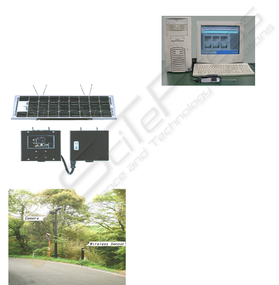
Figure 3 shows the appearance of the remote station
that is divided into two units for the weight balance.
The installation example is shown in Figure 4.
2.4 Base Station
The station is composed of an IBM compatible PC
(personal computer) and the interface for wireless
communication (Figure 5).
The base station can control the remote station
freely. When it receives an image from the remote, it
tells the fact to an operator (or supervisor) by a voice
message. If the operator is absent, the base station
automatically transfers the voice message to a
designated telephone. The station can also store the
transmitted image for at maximum 1,000 days.
Figure 5: Outlook of the base station.
3 THE NUMBER OF REMOTE
STATIONS
3.1 Bit Error Rate and Transmission
Time
In usual case, it is not difficult for the base station to
do image processing faster than the speed of video
signal transmission, if it uses some hardware image
processor
. Then, the performance of the monitoring
system considerably depends on the communication
system.
We roughly estimate the transmission time,
assuming that the bit error stochastically occurs in
Poisson process and that only error detection
function is effective in the communication between
the remote station and the base one.
Let
T
0
and
T be the original necessary
transmission time without any error occurrence and
the average transmission time under the environment
where bit error occurs with the probability
P
b
(BER:
Bit Error Rate), respectively. And, let
S be the
packet length, we have
T = T
0
×(1+
P
b
×
S
) (1)
Based on (1), the relation between
P
b
and T is
illustrated in Figure 6.
Figure 3: Outlook of the remote station.
Figure 4: Example of the installation.
ICINCO 2004 - ROBOTICS AND AUTOMATION
486
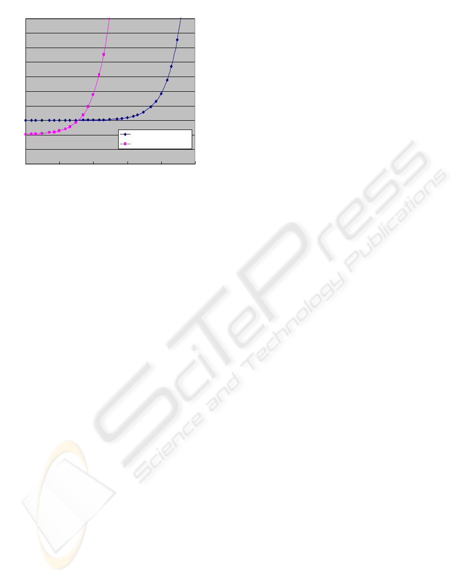
Figure 6: The relation between BER and
transmission time
3.2 Estimation of Connectable Units
Now we suppose that all remote stations have to
send one image data to the base station. Let Rn and
Tc be the number of remote stations and the average
transmission time per image data including dialling
time, etc., respectively. There happens many
collisions in connection to the channel (or line),
however with or without any collision, we can
roughly estimate that the total time for all image data
to be sent is approximately Tc×Rn.
Let C be a miscellaneous time such as dialling
time. And let
Nave and Lt be the average number
of image data to be sent and the effective (or active)
time for communication between the base station and
remote stations, respectively. Then, among those
parameters and the aforementioned time
T
0
and Tc,
the following relational expressions hold.
Tc = T
0
×(1+
P
b
×
S
)+C (2)
Tc×Nave×Rn ≦Lt (3)
From (3), the number of connectable remote
stations Rn can be calculated. Now we assume that
the bit error rate
P
b
is 1.0×10
-7
and that the
transmission rate is 9600bps as aforementioned. In
this case, for the simplicity, we set each parameter as
follows.
T
0
=45 [sec/image],
S
=256 [Byte] =2048 [bit],
P
b
=1.0 × 10
-7
, C=10[sec], Lt=24[hours/day]=
86400[seconds/day], Nave=24[images/day] per
remote station.
From (2) and (3), we have
Tc =55 (4)
Rn≦Lt /(Tc×Nave)=65.5 (5)
Then, as a rough estimation in this case, we can
tell that it is possible to effectively use remote
stations up to 65 units. If we consider the worse
condition of bit error rate 1.0×10
-4
, we can calculate
that about 56 units of remote stations are effective.
4 CONCLUSION
We have developed a compact wireless remote
monitoring system that is capable of outdoor image
acquisition in all weather and all day. The remote
station has a built-in CPU and a camera, which is
attached by a solar battery for power feeding. The
built-in camera can acquire images using auto focus,
auto iris, lens zooming, and night vision functions. It
can automatically change into an infrared one,
depending on the lightness. The remote station is
usually based on an event driven method, i.e., it runs
according to the wireless sensor’s signal. Since each
wireless sensor transmits its own radio ID signal, the
remote station can control the viewpoint of camera
according to the signal. Because of those functions
and the compactness of the remote station, multi
remote stations can be flexibly installed as a
multivision system in arbitrary configuration.
The base station also can control the remote
station by giving a compulsory command signal, so
it can obtain monitored images periodically or at any
time from the remote stations.
The proposed monitoring system is adopted by
more than 20 local governments in Japan and is
currently running well.
REFERENCES
K.Yamada, et al., 2000. A Parking Lot Monitoring System
Using Image Processing. IEEJ Trans. EIS, Vol.120-C,
No.6, pp.784-790, (2000-6) (in Japanese).
T.Sogo, H.Ishiguro, Mohan M.Trivedi, 2000. Real-Time
Human Tracking System with Multiple Omni-
Directional Vision Sensors. IEICE Trans. D-II, Vol.
J83- D-II, No.12, pp.2567-2577, (2000-12) (in
Japanese).
H.Mori, A.Utsumi, J.Ohya, M.Yachida, R.Nakatsu, 2001.
Human Motion Tracking Using Non-synchronous
Multiple Observations. IEICE Trans. D-II,Vol.J84-D-
II, No.1, pp102-110, (2001-1) (in Japanese).
H.Nagahara, Y.Yagi, M.Yachida, 2001. Resolution
Improving Method from Multi-Focal Omnidirectional
Images. IEICE Trans. D-II , Vol.J84-D-II , No.8,
pp1882-1890, (2001-8) (in Japanese).
30
35
40
45
50
55
60
65
70
75
80
1.E-08 1.E-07 1.E-06 1.E-05 1.E-04 1.E-03
BER
Transm ittion time[sec]
Send A C K per packet.
Send A C K w hole data received.
WIRELESS REMOTE MONITORING SYSTEM WITH FLEXIBLY CONFIGURABLE MULTIVISION
487
